
Related Manuals for Atlas Copco SK 160 SA 1


Summary of Contents for Atlas Copco SK 160 SA 1
- Page 1 User and maintenance manual for lighting towers English QLT H40 Pd S2 APP 403D-11G...
- Page 3 QLT H40 Pd S2 APP User and maintenance manual for lighting towers User and maintenance manual .............. 5 Circuit diagrams ..................57 Parts list ....................65 Original instructions Printed matter N° 2954 4960 03 ATLAS COPCO - PORTABLE ENERGY DIVISION www.atlascopco.com 07/2012...
- Page 4 While every effort has been made to ensure that the information in this manual is correct, Atlas Copco does not assume responsibility for possible errors. Copyright 2012, Atlas Copco Airpower n.v., Antwerp, Belgium. Any unauthorized use or copying of the contents or any part thereof is prohibited.This applies in particular to trademarks, model denominations, part numbers and drawings.
-
Page 5: Table Of Contents
Please read the following instructions carefully before starting to use your machine. While every effort has been made to ensure that the information in this manual is correct, Atlas Copco does not assume responsibility for possible errors. Atlas Copco reserves the right to make changes without prior notice. - Page 6 Periodic maintenance Checks and trouble ....32 shooting ..........45 Maintenance schedule.....32 5.1.1 Precautions ........34 Engine troubleshooting....45 5.1.2 Use of maintenance schedule ..34 Solving controller alarms ....45 5.1.3 Use of service paks ......34 Storage of the lighting Preventing low loads .......34 tower ..........46 Maintenance of the alternator..34 Storage..........46...
-
Page 7: Safety Precautions
The policy of Atlas Copco is to provide the users of their Atlas Copco equipment. It is the responsibility of unsafe operating conditions. Take necessary steps to equipment with safe, reliable and efficient products. -
Page 8: General Safety Precautions
The manufacturer does not accept any liability for any All regulating and safety devices shall be General safety precautions damage arising from the use of non-original parts and for maintained with due care to ensure that they The owner is responsible for maintaining the unit in modifications, additions or conversions made without function properly. -
Page 9: Safety During Transport And Installation
If the floor is not level or can vary in inclination, the towbar can be positioned vertically, the locking towing eye. Also check the coupling of the consult Atlas Copco. device must be applied and kept in good order. towing vehicle,... -
Page 10: Safety During Use And Operation
- above 85 dB(A): room to be classified as a noise- appropriate protection, at least safety glasses, for otherwise stated in the Atlas Copco Instruction hazardous area and an obvious warning shall be the operator as well as for any bystander. Do not Book (AIB). - Page 11 15 Safety shoes should be compulsory in any 23 Check the electric cables regularly. Damaged cables 29 When deploying the lighting tower mast, keep in workshop and if there is a risk, however small, of and insufficient tightening of connections may mind following safety precautions: falling objects, wearing of a safety helmet should be cause electric shocks.
-
Page 12: Safety During Maintenance And Repair
Disconnect 18 Maintenance and repair work should be recorded in the alternator cables during arc welding on the unit. Parts shall only be replaced by genuine Atlas Copco an operator’s logbook for all machinery. Frequency replacement parts. -
Page 13: Tool Applications Safety
Tool applications safety Battery safety precautions Apply the proper tool for each job. With the knowledge When servicing batteries, always wear protecting of correct tool use and knowing the limitations of tools, clothing and glasses. along with some common sense, many accidents can be The electrolyte in batteries is a sulphuric acid prevented. -
Page 14: Main Parts
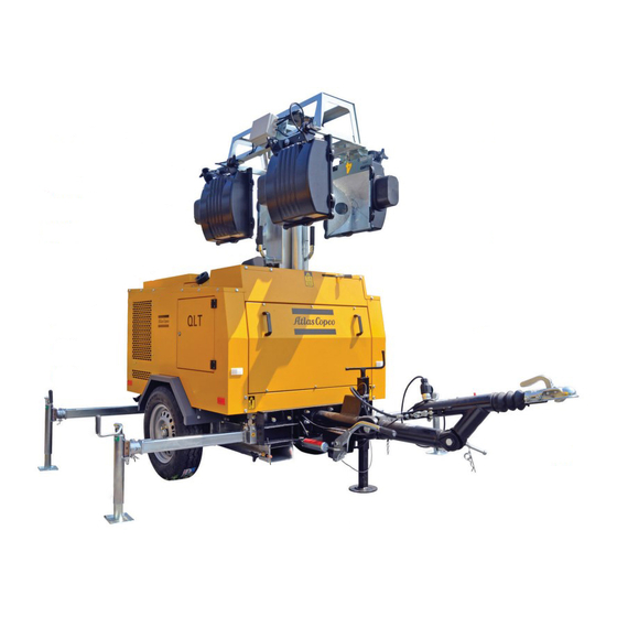
Main parts General description The lighting tower provides an undercarriage (frame, axle and towbar) and 4 spot lights of 1000 W each. The lighting tower is very useful for construction sites where no electricity nor lighting is available. Control panel Data plate Engine exhaust Earth rod... -
Page 15: Markings
Markings A brief description of all markings provided on the Indicates that the lighting tower may Indicates the forklift slots. lighting tower is given hereafter. be refuelled with diesel fuel only. Indicates that this manual should be Indicates that during refuelling it read carefully before putting the is prohibited to smoke and a safe machine into use. -
Page 16: Mechanical Features
Mechanical features 2.3.4 Bodywork Indicates that a horizontal The alternator, the engine, the cooling system, etc. are towbar position is required 2.3.1 Engine and alternator enclosed in a sound-insulated bodywork that can be in case of coupling. opened by means of a side door (and service plates). The alternator is driven by a fluid-cooled diesel engine. -
Page 17: Filler Caps
2.3.7 Filler caps 2.3.9 Undercarriage, road lights and reflectors The fuel filler cap is located on the roof. The filler cap for the engine coolant is accessible via an opening in The lighting tower trolley is manufactured according the roof. to ISO/European road standards currently applicable. -
Page 18: Electrical Features
Electrical features 2.4.1 Control and indicator panel 3A1 ..Controller display 2Q1 ..ECLB or differential protection Interrupts the power supply when a short- To operate the lighting tower a control panel is ES ..Emergency stop button circuit occurs at the load side, or when the installed. -
Page 19: Battery Switch
2.4.2 Battery switch 2.4.4 Outlet sockets 2Q2 ..Circuit breaker for X1 Interrupts the power supply to X1 when a The battery switch is situated inside the sound- A brief description of all outlet sockets and circuit short-circuit occurs at the load side, or when insulated bodywork. -
Page 20: Connection
Installation and connection Lifting The lifting eye, to lift the lighting tower by means of a hoist, is integrated in the bodywork and easily accessible from the outside. When lifting the lighting tower, the hoist has to be placed in such a way that the lighting tower, which must be placed level, will be lifted vertically. -
Page 21: Positioning The Lighting Tower
To release the lighting tower from the towing vehicle, 3.2.2 Positioning the lighting tower carefully follow the procedure below: Follow the steps below to position the lighting tower: 1. Ensure that the hand brake (1) is engaged. The end-of-drive sensor underneath the hand brake must be fully pressed. -
Page 22: Positioning For Transportation
6. Turn the handle (10) at the top of the supporting 3.2.3 Positioning for transportation Once the lighting tower is correctly foot to lower the foot. positioned, fix the earth rod (the 1. Push the DOWN button on the control panel (1) to copper bar for earthing (11)) and lower the mast (see also “Extending the mast”... -
Page 23: Towing
2. Make sure that the jockey wheel is safely fastened 4. Use the handle at the top of each foot to retract the 3.2.4 Towing by its own locking lever to ensure that the lighting 4 feet following the reverse order of the procedure Before commencing towing, ensure you follow the tower is still stable once the stabilizing feet are described in numbers 2-3-4-5 in “Unhooking the... -
Page 24: Positioning Of The Lighting Tower Onto Vehicles
3.2.5 Transportation and positioning Installation of the lighting tower onto 3.3.1 Indoor installation vehicles If the machine is operated in a closed environment, As well as the ability to be towed, the lighting tower can also be easily lifted and moved to difficult areas make sure that there is enough ventilation to remove the exhaust gases from the room where the engine is thanks to its central lifting eye and fork lift holes on... -
Page 25: Outdoor Installation
– Check that the inner earthing system is in ray equipment, audio amplifiers and elevators. compliance with the local legislation. Consult Atlas Copco for measures against the adverse – Use coolant for the engine cooling system. Refer influence of non-linear loads. -
Page 26: Operating Instructions
Operating instructions Before starting Starting and stopping the engine – With the lighting tower standing level, check the In your own interest, always strictly engine oil level and top up if necessary. The oil 4.2.1 Before the engine is started observe relevant safety... -
Page 27: Starting The Engine
2. Before turning the ignition key (2) into the 5. The controller (7) will activate the engine This procedure must be carried out START position (3) to start the engine, please protection systems. If any of the parameters each time that you start the lighting remember that on diesel engines with indirect deviate from the norm (for example, low oil or tower. -
Page 28: Switching Off The Engine
4. Turn the key counterclockwise into the OFF 4.2.4 Switching off the engine Operating the lighting tower position (3) to switch off the engine Follow the instructions below to switch the engine off 4.3.1 Aligning the spotlights correctly: 1. Check that the glass panes of the lights (1) are in 1. -
Page 29: Extending The Mast
2. Adjust the inclination of the spotlight using the on page 27. (If there is no fuel, there will be a 4.3.2 Extending the mast wheels (2) placed at the sides of the spotlight. message on the display and an acoustic alarm.) The mast cannot be raised if the 3. -
Page 30: Switching On The Spotlights
Do not extend the mast at a wind speed stronger than 80 km/h. 4.3.3 Switching on the spotlights 1. Place the 4 automatic switches (LAMP 1, LAMP 2, LAMP 3 and LAMP 4) (1) in the ON position. 4.3.4 Switching off the spotlights To switch the lights off, follow the procedure 3. -
Page 31: Connecting Appliances
5. The mast is lowered completely when the end-of- 5. Make sure that the load does not exceed the Connecting appliances run button (4) is pushed down and the intermittent nominal power of the generating set as indicated 1. Wait 3 or 4 minutes before connecting the appli- siren stops. -
Page 32: Periodic Maintenance
2912 6409 05 For the most important subassemblies, Atlas Copco has developed service kits that combine all wear parts. These service kits offer you the benefits of genuine parts, save on administration costs and are offered at reduced price, compared to the loose components. Refer to the parts list for more information on the contents of the service kits. - Page 33 Lighting towers in standby application have to be tested on a regular basis. At least once a month the engine should run for minimum 30 Inspection by Atlas Copco Service technician minutes at a high load (50% - 70%) that the engine reaches its operating temperature.
-
Page 34: Precautions
The order number of the Service Paks are listed in the lighting tower. – Do not carry out any change or modification to Atlas Copco Parts list (ASL). Order Service Paks at any part of the lighting tower or its electric your local Atlas Copco dealer. -
Page 35: Engine Maintenance Procedures
Engine maintenance procedures – Regularly perform maintenance work and replace – Do not smoke and maintain a safe distance from 5.4.1 Engine oil level check parts as indicated in the Engine Operation flames and sparks while maintenance is being Consult the Engine Operation Manual for the oil Manual. -
Page 36: Engine Oil And Oil Filter Change
– Check the engine oil level by using the oil level – Dispose of waste oil properly. All lubricant oils 5.4.2 Engine oil and oil filter change dipstick (2). for engines and hydraulic circuits, both mineral Regularly perform maintenance work and replace and synthetic, are classified as dangerous waste. -
Page 37: Coolant Check
(no leaks, clean,...). min and max levels. – The pH-meter can be ordered from Atlas Copco – Check the condition of the coolant. Do not open the radiator cap if the with part number 2913 0029 00. -
Page 38: Adjustments And Service Procedures
5.5.1 Battery care (charging or refilling). – From the Atlas Copco Instruction book, determine Before handling batteries, read the the amount of PARCOOL EG required and pour – Take out the battery. relevant safety precautions and act into the radiator top tank. -
Page 39: Replacing Fuel Filter Element
5.5.1.3 Recharging a battery 5.5.1.5 Periodic battery service 5.5.2 Replacing fuel filter element Before and after charging a battery, always check the – Keep the battery clean and dry. electrolyte level in each cell; if required, top up with – Keep the electrolyte level at 10 to 15 mm above distilled water only. -
Page 40: Servicing Air Filter Engine
Servicing air filter engine 5.5.3.2 Recommendation 5.5.3.4 Replacing the air filter element – Release the snap clips (1) and remove the dust trap The Atlas Copco air filters are 5.5.3.1 Main parts (2). Clean the trap. specially designed – Remove the element (4) from the housing (5). -
Page 41: Air Cooling Circuit
2. Remove the lamp, first releasing the safety spring 5.5.4 Air cooling circuit 5.5.5 Replacing the lamps (2) placed around the lamp and then unscrewing Check every day that all the air Do not touch the lamps when they the lamp from its seat (3). cooling circuits are not clogged with are still hot without having taken all dust or other particles. -
Page 42: Ordering Spare Parts
3. Install the new lamp and replace the safety spring 5.5.6 Ordering spare parts Resetting service alarms (2). It is possible to order spare parts for the lighting tower 4. Lock the protective glass using the 5 clamps and by making reference to the parts as mentioned in the remember to carefully tighten the screws with a enclosed Parts List manual. -
Page 43: Engine Consumable Specifications
PAROIL releases excess heat efficiently, whilst Engine consumable Specifications PAROIL maintaining excellent bore-polish protection to limit PAROIL from Atlas Copco is the ONLY oil tested specifications oil consumption. and approved for use in all engines built into Atlas PAROIL has an excellent Total Base Number (TBN) Copco compressors, generators and lighting towers. -
Page 44: Engine Coolant Specifications
1604 5308 00 generators and lighting towers. personal injury from the splash of hot 1604 5307 01 coolant. Atlas Copco's PARCOOL EG extended life coolant is It is strongly recommended to use the new range of organic coolants purpose designed barrel 55.2 7.35... -
Page 45: Checks And Trouble Shooting
Checks and trouble Engine troubleshooting shooting Refer to the Engine Operation manual for engine troubleshooting. Never perform a test run with connected power cables. Never Solving controller alarms touch electrical connector The manual for the controller that also accompanies without a voltage check. the machine, will provide you with more information When a failure occurs, always on error messages displayed. -
Page 46: Storage Of The Lighting Tower
Storage of the lighting tower Storage Preparing for operation after storage – Store the lighting tower horizontally in a dry, frost-free room which is well ventilated. Before operating the lighting tower again, remove the wrapping, VCI paper and silica gel bags and check the –... -
Page 47: Disposal
(for example sand, sawdust) and recyclable materials. dispose it according the applicable local disposal Your Atlas Copco lighting tower consists for the most regulations. Do not drain into the sewage system or part of metallic materials, that can be remelted in surface water. -
Page 48: Technical Specifications Of The Lighting Tower
Technical specifications of the lighting tower Technical specifications of the engine/alternator/unit 50 Hz Rated frequency 50 Hz Reference conditions 1) 4) Rated speed 1500 rpm Generator service duty Absolute air inlet pressure 100 kPa Relative air humidity 31.5% Air inlet temperature 25°C Maximum ambient temperature 50°C... - Page 49 Standard IEC34-1 Alternator ISO 8528-3 Make Sincro Model SK 160 SA 1 Rated output, class H temperature rise 9 kVA rating type acc. ISO 8528-3 S1 40/125°C cl. H Degree of protection IP 21 Insulation stator class Insulation rotor class...
- Page 50 Number of cylinders Swept volume 1.13 l Speed governing mechanical Capacity of oil sump 4.2 l Capacity of cooling system 4.9 l Electrical system 12 Vdc Emission compliance EU STAGE II Circuit-breaker, 1ph. Power circuit Number of poles Thermal release It (thermal release is higher at 25°C) 32 A Magnetic release Im 5-10 x In...
- Page 51 Weight at the towing eye (ready to operate) (adj. towbar - stretched) 70 kg Weight at the towing eye (ready to operate) (adj. towbar - folded) 74 kg Weight at the towing eye (ready to operate) (fixed towbar) 52 kg Notes Reference conditions for engine performance to ISO 3046-1.
- Page 52 50 Hz - Derating Table (in %, 100% is declared power in "Performance Data") Temperature Height (°C) 1000 1500 2000 2500 3000 3500 4000 For use of generator outside these conditions, please contact Atlas Copco. - 52 -...
-
Page 53: Average Illumination Versus Distance
Average illumination versus distance 10m / 200 Lx 25m / 100 Lx 35m / 50 Lx - 53 -... -
Page 54: Dimension Drawing
Dimension drawing - 54 -... -
Page 55: Conversion List Of Si Units Into British Units
Conversion list of SI units Dataplate Maximum permitted total weight of the vehicle into British units Maximum permitted axle load Maximum permitted load on towing eye 1 bar 14.504 psi ATLAS COPCO AIRPOWER n.v. Company code 0.035 oz ##### Product code -YA3- ##### ##### 1 kg 2.205 lbs... - Page 56 - 56 -...
- Page 57 Circuit diagrams - 57 -...
- Page 58 A1-23591B2 Power circuit - 58 -...
- Page 59 A1-23591B2 Power circuit LEGEND ENGINE DEVICES Heater candle control relay Battery charger run state relay Start relay Fuel valve relay Oil pressure gauge Water temperature gauge Fuel level gauge Low oil pressure switch High water temperature switch Low water level switch - 59 -...
- Page 60 A1-23591B2 Control circuit LEGEND TOWER LIGHT CONTROL Tower light up actuator Tower light down actuator Tower light down position switch Hand brake position switch Up push button command Down push button command Interface relay Tower light up relay Tower light down relay - 60 -...
- Page 61 A1-23591B2 Control circuit LEGEND TOWER LIGHT CONTROL +BAT Red 4mm Battery positive pole -BAT Grey 4 mm Battery negative pole Green 1.5 mm D+ signal for battery charger Black 2.5 mm Engine start command Yellow 1.5 mm Fuel valve command White 1.5 mm Low oil pressure Azure 1.5 mm...
- Page 62 A1-23591B2 Trolley connector - 62 -...
- Page 63 A1-23581B2 Lamps - 63 -...
- Page 64 - 64 -...
- Page 65 Parts list - 65 -...
- Page 66 SERVICE PAK PART NUMBER DESIGNATION 2912 6409 05 SERVICE PAK 500 H QLT H40 FUEL FILTER OIL FILTER AIR FILTER - 66 -...
- Page 67 ENGINE AND ALTERNATOR ASSEMBLY - STANDARD - SINCRO ALTERNATOR PART NUMBER DESIGNATION 3002 5000 00 ENGINE 2914 8348 00 FUEL FILTER 2914 8349 00 OIL FILTER 2914 9857 00 AIR FILTER 3002 5002 00 PAD ANTI VIBR. 3002 5004 00 SILENCER 3002 5005 00 CLAMP...
- Page 68 UNDERCARRIAGE - STANDARD PART NUMBER DESIGNATION 3002 5016 00 AXLE 3002 5017 00 TYRE ASSY 3002 5018 00 SUPPORT 3002 5019 00 TOWBAR 3002 5020 00 CLAMP 3002 5021 00 JOCKEY WHEEL 3002 5022 00 3002 5023 00 SWITCH 3002 5024 00 EYE TOWING 2914 8903 00 2914 8904 00...
- Page 69 BRAKE DRUM ASSEMBLY - STANDARD PART NUMBER DESIGNATION 2914 8926 00 WHEEL BOLT 2914 8927 00 HUB CAP 2914 8928 00 SPLIT PIN 2914 8929 00 BRAKE DRUM 2914 8930 00 SPRING 2914 8931 00 LEVER 2914 8932 00 2914 8933 00 WASHER 2914 8934 00 SLOTTED HEX NUT...
- Page 70 ADJUSTABLE TOWBAR - STANDARD PART NUMBER DESIGNATION 3002 5271 00 MIDDLE ARM 3002 5253 00 SWITCH 3002 5254 00 MIDDLE ARM BLOCK FIFTH WHEEL 3002 5255 00 BALL COUPLING BLOCK FIFTH WHEEL 3002 5256 00 PRELOADED SPRING 3002 5257 00 REINFORCED FRAME 3002 5258 00 BALL COUPLING GROUP...
- Page 71 ADJUSTABLE TOWBAR ASSEMBLY - STANDARD PART NUMBER DESIGNATION 3002 5269 00 MS2 HEAD - COMPLETE 3002 5238 00 PERFORATED ROD - COMPLETE 1 3002 5239 00 RUBBER BELLOWS 3002 5240 00 M6 X 10 8.8 UNI 5931 SCREW 3002 5241 00 O- RING 50X5 3002 5270 00 2022.010 VIBRATION DAMPER...
- Page 72 FRAME AND PANELS - STANDARD PART NUMBER DESIGNATION 3002 5025 00 FRAME 3002 5026 00 SUPPORT 3002 5027 00 TANK 3002 5028 00 ASSEMBLY 3002 5029 00 ASSEMBLY 3002 5030 00 BUMPER 3002 5031 00 3002 5032 00 FOOT 3002 5033 00 LOCK SCREW 3002 5034 00 3002 5035 00...
- Page 73 BODYWORK - STANDARD PART NUMBER DESIGNATION 3002 5038 00 ROOF PANEL 3002 5039 00 PANEL 3002 5040 00 PANEL 3002 5041 00 3002 5042 00 PANEL 3002 5043 00 PANEL 3002 5044 00 3002 5045 00 DOOR 3002 5046 00 PLATE 3002 5047 00 FLANGE...
- Page 74 FUEL TANK ASSEMBLY - STANDARD PART NUMBER DESIGNATION 3002 5067 00 TANK FUEL 3002 5068 00 FLANGE 3002 5069 00 FLANGE 3002 5070 00 WASHER 3002 5071 00 SENSOR LEVEL 3002 5072 00 FUEL CAP 3002 5073 00 3002 5074 00 WASHER - 74 -...
- Page 75 SUPPORT FOR TOWER COLUMN AND FRAME - STANDARD PART NUMBER DESIGNATION 120 65 3002 5075 80 MAST SUPPORT 3002 5075 00 SUPPORT 3002 5076 00 SUPPORT 3002 5077 00 PLATE 3002 5078 00 SLEEVE 3002 5079 00 ARRESTER 3002 5080 00 SPACER 3002 5081 00 HANDGRIP...
- Page 76 TOWER - FIRST ELEMENT STANDARD PART NUMBER DESIGNATION 3002 5096 00 ELEMENT 3002 5097 00 35 40 3002 5098 00 3002 5099 00 3002 5100 00 BEARING 3002 5101 00 PULLEY 3002 5102 00 CABLE 3002 5103 00 BUFFER 3002 5104 00 BUFFER 3002 5105 00 BUFFER...
- Page 77 TOWER - SECOND ELEMENT STANDARD PART NUMBER DESIGNATION 3002 5109 00 ELEMENT 60 35 40 3002 5110 00 3002 5111 00 3002 5112 00 3002 5113 00 BEARING 3002 5114 00 PULLEY 3002 5115 00 CABLE 3002 5116 00 BUFFER 3002 5117 00 BUFFER 3002 5118 00...
- Page 78 TOWER - THIRD ELEMENT STANDARD PART NUMBER DESIGNATION 3002 5124 00 ELEMENT 3002 5125 00 40 35 3002 5126 00 3002 5127 00 3002 5128 00 BEARING 3002 5129 00 PULLEY 3002 5130 00 CABLE 3002 5131 00 BUFFER 3002 5132 00 BUFFER 3002 5133 00 BUFFER...
- Page 79 TOWER - FOURTH ELEMENT STANDARD PART NUMBER DESIGNATION 3002 5135 00 ELEMENT 40 35 3002 5136 00 3002 5137 00 3002 5138 00 3002 5139 00 BEARING 3002 5140 00 PULLEY 3002 5141 00 CABLE 3002 5142 00 BUFFER 3002 5143 00 BUFFER 3002 5144 00 BUFFER...
- Page 80 TOWER - FIFTH ELEMENT STANDARD PART NUMBER DESIGNATION 3002 5146 00 ELEMENT 3002 5147 00 CABLE 3002 5148 00 WASHER LOCK 3002 5149 00 3002 5150 00 BEARING 3002 5151 00 PULLEY 3002 5152 00 CABLE 3002 5153 00 BUFFER 3002 5154 00 BUFFER 3002 5155 00...
- Page 81 TOWER - SIXTH ELEMENT STANDARD PART NUMBER DESIGNATION 3002 5157 00 ELEMENT 3002 5158 00 CABLE 3002 5159 00 WASHER LOCK 3002 5160 00 3002 5161 00 BEARING 3002 5162 00 PULLEY 3002 5163 00 CABLE 3002 5164 00 BUFFER 3002 5165 00 BUFFER 3002 5166 00...
- Page 82 TOWER - SEVENTH ELEMENT STANDARD PART NUMBER DESIGNATION 3002 5168 00 ELEMENT 3002 5169 00 BUFFER 3002 5170 00 BUFFER 3002 5171 00 BUFFER - 82 -...
- Page 83 ROAD SIGNALISATION - STANDARD PART NUMBER DESIGNATION 3002 5172 00 SUPPORT 3002 5173 00 SUPPORT 3002 5174 00 LAMP ASSY 3002 5175 00 LAMP 3002 5176 00 CABLE/WIRE 3002 5177 00 BOLT 3002 5178 00 HANDGRIP 3002 5179 00 WASHER 3002 5180 00 WASHER 3002 5181 00...
- Page 84 HYDRAULIC SYSTEM - STANDARD PART NUMBER DESIGNATION 3002 5186 00 HYDRAULIC PUMP 3002 5187 00 3002 5188 00 CYLINDER 3002 5189 00 PIPE 3002 5190 00 NIPPLE 3002 5191 00 VALVE 3002 5192 00 MOTOR 3002 5193 00 GEARBOX 3002 5194 00 PUMP 3002 5195 00 3002 5196 00...
- Page 85 ELECTRIC PANEL - STANDARD PART NUMBER DESIGNATION 3002 5198 80 FRONT PANEL 3002 5199 00 3002 5200 00 DOOR 3002 5201 00 HINGE 3002 5202 00 LOCK 3002 5203 00 GUIDE 3002 5204 00 SCREW 3002 5205 00 CONTROL UNIT 3002 5206 00 EMERGENCY STOP 3002 5207 00...
- Page 86 STICKER - STANDARD PART NUMBER DESIGNATION 3002 5264 00 STICKER SOCKET 1 (230V/16A) +SOCKET 2 (230V/16A) 3002 5265 00 "STICKER SOCKET 1 (230V/16A) + SOCKET 2 (230V/32A) 3002 5266 00 "STICKER SWITCH GENSET/ MAINS +SOCKET 1 (230V/16A) + PLUG (230V/32A) 3002 5267 00 "STICKER LAMP1/2/3/4 + SOCKET...
- Page 87 MARKINGS - STANDARD - 87 -...
- Page 88 PART NUMBER DESIGNATION 0690 1132 00 HOUSE MARK 0690 1116 00 HOUSE MARK 1079 9921 03 INFORMATION LABEL 1626 5650 00 LABEL 1079 9922 07 INFORMATION LABEL 1604 3317 07 LABEL NOISE 1079 9917 97 INFORMATION LABEL 1079 9902 00 WARNING LABEL 1079 9930 67 LABEL...
- Page 89 ENGINE AND ALTERNATOR ASSEMBLY - MECC ALTE ALTERNATOR - OPTIONS PART NUMBER DESIGNATION 2914 8901 00 ALTERNATOR (MECC ALTE) 2914 8902 00 PAD ANTI VIBR. - 89 -...
- Page 90 TOWING EYES - DIN EYE, ITA EYE NATO EYE OPTIONS PART NUMBER DESIGNATION DIN EYE 1626 5914 00 TOWING EYE 1611 7410 82/01 ITA EYE 1626 5678 00 TOWING EYE 1611 7407 82/00 NATO EYE 1626 5942 00 TOWING EYE NATO 1611 7411 82/01 - 90 -...
- Page 91 TOWING EYES - BALL COUPLING EYE, BNA EYE FRENCH EYE OPTIONS PART NUMBER DESIGNATION BALL COUPLING EYE 1626 5914 00 TOWING EYE 1611 7406 82/01 BNA EYE 1626 5678 00 TOWING EYE 1611 7413 82/01 FRENCH EYE 1626 5942 00 TOWING EYE 1611 7412 82/01 - 91 -...
- Page 92 Following documents are provided with this unit: – Test Certificate – EC Declaration of Conformity: EC DECLARATION OF CONFORMITY We, Atlas Copco Airpower n.v., declare under our sole responsibility, that the product Machine name : Power generator (< 400 kW) Commercial name : Serial number Which falls under the provisions of article 12.2 of the EC Directive 2006/42/EC on the approximation of the...
- Page 94 www.atlascopco.com...
Need help?
Do you have a question about the SK 160 SA 1 and is the answer not in the manual?
Questions and answers