
Related Manuals for Bosch CM371B


Summary of Contents for Bosch CM371B
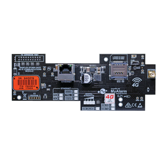
- Page 1 CM371B IP Combo Module - 4G LTE CAT 1 Security Systems Installer Reference Guide Security System...
-
Page 2: Getting Started
There are four main steps required to configure the CM371B for reporting to the control room. The instruc- Experiment with the position of the antenna to find the tions assume that you already have purchased a SIM card best signal strength before fixing it in place. - Page 3 2) Signal Strength in dB Amber LED Meaning 3) IMEI Number Half Duplex Activity 4) Radio Firmware Revision Full Duplex Activity / Off 5) SIM Card Present Blinking Collision Activity Table 4: RJ45 Socket Indicator Meanings Bosch Security Systems 7/24 CM371BIRG FTR1.1...
- Page 4 SIM Balance Recharge Reminder Function The SIM Balance feature of the SMS Control App is no longer supported due to network Note provider changes. Scan Here (iOS Version) Bosch Security Systems 7/24 CM371BIRG FTR1.1...
- Page 5 CM371B Installer Reference Guide GPRS Using The CM371B 4G Radio The APN Server Name, APN User Name and APN Password menu’s need to be configured before the 4G radio can establish a GPRS or data connection with the telco provider.
-
Page 6: System Status
<User Code>,DOOR,1,2,3,LOCK Lock Multiple Doors With Confirmation <User Code>,DOOR,1,2,3,LOCK,CONFIRM Check Status Of A Door <User Code>,DOOR,1,STATUS Check Status Of Multiple Doors <User Code>,DOOR,1,2,3,STATUS Check System Status <User Code>,SYSTEM,STATUS Table 5: GSM SMS String Commands Bosch Security Systems 7/24 CM371BIRG FTR1.1... - Page 7 Figure 2: IP Config Showing Gateway and Subnet Mask tion Link RAS software and it is recommended that you make use of these when configuring the CM371B. At this IPCONFIG will list the Default Gateway, Subnet Mask as point you should connect your laptop to the same LAN well as the IP address of the PC which executed the com- that the CM371B is connected and then run Solution Link.
- Page 8 Figure 4: Customer Panel Form Press the OK button and the assistant will begin scan- ning the private network LAN for the presence of CM371B modules. If more than one module is found, select the one from the list whose MAC address matches the one you are installing and press the [OK] button.
- Page 9 Go to the Ethernet Module section in the Devices tab and uncheck the “Obtain IP Address Automatically” option Figure 11: Configuring the Transmission Format then enter the IP Address of the CM371B, the Subnet Mask and the Default Gateway in the fields provided and then save the changes.
- Page 10 07701 (default IP RAS Port) incoming connections from a specific IP Address. In the to the internal IP address of the CM371B which is pro- default state the RAS IP Address is set to 000.000.000.000 grammed in MENU 6-6-0 on the Solution 6000.
- Page 11 Optional AN110 High Gain Outdoor Antenna configured to reserve or lock down the IP Address which was assigned to the CM371B module when it was first For installations where adequate signal strength is not connected to the LAN. See the Module IP Address loca- available using the supplied indoor antenna, an optional tion which is MENU 6-6-0 on the Solution 6000 panel.
-
Page 12: Customer Details
Installer Reference Guide CM371B Customer Details Use this section to record the customer details for this CM371B module. This information may also be required when seeking technical support. Customer Name:: Module Serial No: MAC Address: IP Address Public: IP Address Private:... -
Page 13: Specifications
Antenna: Quad Band Omni Directional with Magnetic Mount, integrated lead and SMA Connector. 3dbi gain - 50 ohm Module Connection: The CM371B is mounted directly to the expansion port on the control panel PCB. Two plastic standoffs are supplied to support the module and these should be connected to the control panel before installing the CM371B. - Page 14 Bosch Security Systems Level 2, 21 Solent Circuit Baulkham Hills, NSW 2153 Australia Phone: 1300 026 724 RoHS www.boschsecurity.com.au © 2024 Bosch Security Systems BLCM371BIRG Issue FTR1.1...
Need help?
Do you have a question about the CM371B and is the answer not in the manual?
Questions and answers