
Related Manuals for MCZ MAY AIR 7 S1


Summary of Contents for MCZ MAY AIR 7 S1
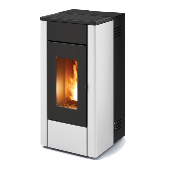
- Page 1 INSTALLATION GUIDE SEALED PELLET STOVE MAY AIR 7 S1 MAY AIR 7 UP! S1 Translation of original instructions...
-
Page 2: Table Of Contents
TABLE OF CONTENTS TABLE OF CONTENTS ....................II INTRODUCTION ......................1 1-WARNINGS AND WARRANTY CONDITIONS ..............2 2-INSTALLATION ......................9 3-DRAWINGS AND TECHNICAL SPECIFICATIONS ............18 5- SMOKE OUTLET .....................23 6-INSTALLATION AND ASSEMBLY ................29 7-OPENING THE DOORS .....................38 8-CONNECTION TO ADDITIONAL DEVICES ..............39 9-LOADING THE PELLETS ...................40 10-ELECTRICAL CONNECTION ..................41 11-FIRST START-UP ....................42 12-CONTROL PANEL ....................44... -
Page 3: Introduction
No part of this manual may be translated into other languages, adapted and/or reproduced, even in part, in other mechanical and/or electronic form or media, for photocopies, recordings or other, without the prior written authorisation of MCZ Group Spa. The company reserves the right to make changes to the product at any time without prior notice. The owner company reserves its rights according to law. -
Page 4: 1-Warnings And Warranty Conditions
1-WARNINGS AND WARRANTY CONDITIONS SAFETY PRECAUTIONS • Installation, electrical connection, operating check and maintenance must only be carried out by authorised and qualified personnel. • Install the product in accordance with all local and national legislation and regulations in force in the region or state. • Only use the fuel recommended by the manufacturer. - Page 5 1-WARNINGS AND WARRANTY CONDITIONS • Do not dry laundry on the product. Any drying racks or the like must be kept at a safe distance from the product. Fire hazard. • All liability for improper use of the product is entirely borne by the user and relieves the manufacturer of any civil and criminal liability.
- Page 6 1-WARNINGS AND WARRANTY CONDITIONS exposed to weathering. • It is recommended not to remove the feet that support the product in order to ensure adequate insulation, especially if the flooring is made of flammable materials. • In the event of a malfunction of the ignition system, do not force it on by using flammable materials.
- Page 7 1-WARNINGS AND WARRANTY CONDITIONS INFORMATION: Please contact the retailer or qualified personnel authorised by the company to resolve a problem. • Only use the fuel specified by the manufacturer. • When the product is switched on for the first time, it is normal for it to emit smoke due to the paint heating up for the first time. Therefore make sure the room it is installed in is well-ventilated.
- Page 8 1-WARNINGS AND WARRANTY CONDITIONS and therefore the product is used correctly. Replacement of the entire system or repair of one of its components does not extend the warranty period, and the original expiry date remains unchanged. The warranty covers the replacement or free repair of parts recognised as being faulty at source due to manufacturing defects. In the event of a fault, to benefit from the warranty, the customer must keep the warranty certificate and provide it along with the document given at the time of purchase to the Technical Service Centre.
- Page 9 1-WARNINGS AND WARRANTY CONDITIONS SPARE PARTS In the event of a malfunction, consult the retailer who shall forward the call to the Technical Assistance Department. Only use original spare parts. The retailer or service centre can provide all necessary information regarding spare parts. We do not recommend waiting for the parts to get worn out before having them replaced.
- Page 10 1-WARNINGS AND WARRANTY CONDITIONS Our solid bio-combustible products, (hereinafter called “Products”) are designed and manufactured in compliance with one of the following European standard harmonised to Regulation (UE) no. 305/2011 for construction products: EN 14785: “Residential space heating appliances fired by wood pellets” EN 13240: “Roomheaters fired by solid fuel.”...
-
Page 11: 2-Installation
2-INSTALLATION The instructions in this chapter refer explicitly to the Italian installation regulation UNI 10683. In any case, always observe the regulations in force in the country of installation. PELLETS Wood pellets are manufactured by extruding sawdust which is produced during the processing of natural dried wood (without paint). The compactness of the material is guaranteed by the lignin contained in the wood itself and allows the pellets to be produced without glue or binders. - Page 12 If the floor is made of wood, it is recommended to fit a floor protection sheet in compliance with the standards in force in the country of installation. Non-flammable walls Flammable walls MAY AIR 7 S1/ MAY AIR 7 UP! S1 A = 5 cm A = 20 cm...
- Page 13 2-INSTALLATION FOREWORD This Flue chapter has been drawn up with reference to the provisions of European Standards (EN13384 - EN1443 - EN1856 - EN1457). The chapter provides indications for installing an efficient and correct flue but is under no circumstances to substitute the regulations in force, which the qualified manufacturer must be in possession of.
- Page 14 2-INSTALLATION TECHNICAL SPECIFICATIONS Have the efficiency of the flue checked by an authorised technician. The flue must be sealed against flue gases, in a vertical direction without narrowing, be made with materials impermeable to smoke, condensation, thermally insulated and suitable to resist normal mechanical stress over time (we recommend fireplaces made of A/316 or refractory material with insulated round section double chamber).
- Page 15 2-INSTALLATION ROOF AT 60° ROOF AT 45° 45° 60° A = MIN. 2.60 metres A = MIN. 2.00 metres FIGURE 6 FIGURE 5 B = DISTANCE > 1.20 metres B = DISTANCE > 1.30 metres C = DISTANCE < 1.20 metres C = DISTANCE <...
- Page 16 2-INSTALLATION MAINTENANCE The flue must be kept clean, since the deposit of soot or unburnt oils reduces the cross-section, blocking the draught and thus compromising the efficient operation of the stove and, if large build-ups accumulate, can catch fire. The flue and chimneypot must be cleaned and checked by a qualified chimney sweep at least once a year.
- Page 17 2-INSTALLATION EXTERNAL AIR INLET It is mandatory to provide an adequate external air inlet that supplies the combustion air required for the product to work properly. The flow of air between the outside and the installation room may be direct, through an inlet in an external wall of the room (preferable solution see Figure 9 a), or indirect, via air intake from adjoining rooms and connecting permanently with the installation room (see Figure 9 b).
- Page 18 2-INSTALLATION In order to fully enhance the sealed features and heating performance of this Oyster appliance, and thus to avoid fitting a free air intake in the room. It is recommended to connect the air required for combustion directly to the external air intake through 060 mm piping with a maximum length of 3 linear metres, using the suitable “j”...
- Page 19 2-INSTALLATION EXAMPLES OF CORRECT INSTALLATION 1. Installation of Ø120mm flue with hole for the passage of the pipe increased by: minimum 100mm around the pipe if next to non- flammable parts such as cement, brick, etc.; or minimum 300mm around the pipe (or as required by plate data) if next to flammable parts such as wood etc.
-
Page 20: 3-Drawings And Technical Specifications
3-DRAWINGS AND TECHNICAL SPECIFICATIONS DRAWINGS AND CHARACTERISTICS MAY AIR 7 S1 STOVE DIMENSIONS Ø80 Ø60... - Page 21 3-DRAWINGS AND TECHNICAL SPECIFICATIONS MAY AIR 7 UP! STOVE DIMENSIONS S1 Ø60 Ø80 Technical Dept. - All rights reserved - Reproduction prohibited...
- Page 22 3-DRAWINGS AND TECHNICAL SPECIFICATIONS TECHNICAL SPECIFICATIONS MAY AIR 7 S1 / MAY AIR 7 UP! S1 Energy Efficiency Class Nominal output power 7.0 kW (6020 kcal/h) Minimum output power 2.5 kW (2150 kcal/h) Efficiency at Max 90.5% Efficiency at Min 95.0%...
- Page 23 3-DRAWINGS AND TECHNICAL SPECIFICATIONS PREPARATION AND UNPACKING Remove all the parts of the packaging (polystyrene, wood, plastic). All packaging materials can be reused for similar use or disposed of as urban solid waste, in accordance with the standards in force. After having removed the packaging make sure the product is intact.
- Page 24 3-DRAWINGS AND TECHNICAL SPECIFICATIONS Therefore, the end user is responsible for product storage, disposal or possible recycling in compliance with the relative applicable laws in force. Do not store the stove unit or its cladding without their packaging. Position the stove and connect it to the flue. Remove the plastic tie that fastens the top to the structure of the stove. If the stove needs to be connected to an outlet pipe which goes through the rear wall (to connect to the flue), take utmost care to make sure that the joint is not forced.
-
Page 25: 5- Smoke Outlet
5- SMOKE OUTLET REAR SMOKE OUTLET (MAY AIR 7 S1) The stove will leave the factory as per standard with the elbow for the rear outlet as shown in the image below. When installing with rear outlet, connect the external smoke pipe to the stove... - Page 26 5- SMOKE OUTLET TOP SMOKE OUTLET (MAY AIR 7 UP! S1) Preliminary steps: • prepare the components of the top smoke outlet kit • leave the stove without claddings (including rear panels) KIT CONTENTS POS. DESCRIPTION POS. DESCRIPTION COMPLETE PELLET COVER TEE FITTING CAP GASKET REAR OUTLET CLOSING CAP BLACK OPEN CAP...
- Page 27 5- SMOKE OUTLET • remove the elbow “H” • mount the fitting “L” , the gasket “g” and the cap “Q” for top outlet Technical Dept. - All rights reserved - Reproduction prohibited...
- Page 28 5- SMOKE OUTLET • remove the knockout hole “S” • take the cap “P” from the kit • fix the cap “P” to the stove with the nuts“k” (nut M4 6S) • between the cap “P” and the stove structure, position the two washers “y” (washer for M6) •...
- Page 29 5- SMOKE OUTLET • punch the knockout hole “Q” • fix the pipe “U” with the screw “w” (self tapping screw 4.2x13) Before fixing the pipe “U” with the screw “w” centre the pipe with respect to the insertion hole, otherwise the hopper cover might not open.
- Page 30 5- SMOKE OUTLET • take the pellet cover “B” (included in the kit) • use the 2 screws “x” taken out for removal of the cover “A” (self tapping screw M4x12) • fasten the cover “B” to the structure with the two screws “x” Attention! The cup (end part of the linear pipe) must be AT LEAST 200 mm from the stove cover as indicated in the drawing below;...
-
Page 31: 6-Installation And Assembly
6-INSTALLATION AND ASSEMBLY Live electrical parts: only power the product once it has been fully assembled. On delivery, the stove has no metal cladding, as shown in the image below. Take the box with the package (figure below) and prepare the material for installation. METAL CLADDING POS. - Page 32 6-INSTALLATION AND ASSEMBLY DISASSEMBLING THE BACK PANEL The stove is delivered with the back panels installed on the product. If you need to remove the side panels for technical service or cleaning or to install the top outlet, proceed as follows: •...
- Page 33 6-INSTALLATION AND ASSEMBLY • repeat the same procedure with the other panel To put the panels back in place, perform the same operations in the opposite order. Technical Dept. - All rights reserved - Reproduction prohibited...
- Page 34 6-INSTALLATION AND ASSEMBLY ASSEMBLING LOWER FRONT CLADDING Before assembling the chosen side cladding, mount the lower panel “D” as follows: • Take the lower panel “D” and the 4 screws“x” from the box • Secure the panel “D” to the structure of the stove using the 4 screws“x”...
- Page 35 6-INSTALLATION AND ASSEMBLY ASSEMBLING THE SIDE CLADDING To install the side cladding, proceed as follows: • remove the top “E” (simply lift it from its seat) • take a panel “C” (there is no right or left as they are symmetrical) and the two rubber buffers “y” •...
- Page 36 6-INSTALLATION AND ASSEMBLY • Take metal side “C” and insert the holes “v” in the hooks “z” on the stove frame.
- Page 37 6-INSTALLATION AND ASSEMBLY • fasten the panel “C” at the top with the two screws “x” Technical Dept. - All rights reserved - Reproduction prohibited...
- Page 38 6-INSTALLATION AND ASSEMBLY • repeat the same procedure with the other panel “C” • refit the top “E” placing it on the rubber buffers “y”...
- Page 39 6-INSTALLATION AND ASSEMBLY ACCESS TO THE ELECTRONIC BOARD The circuit board “J” is on the right side (handle side). If you need to access the board, you must remove the back side panel as explained above. ACCESS TO THE GEARMOTOR You must remove the side panel to access the gearmotor.
-
Page 40: 7-Opening The Doors
7-OPENING THE DOORS OPENING THE DOOR OF THE FIREBOX To open the firebox door, fit the cold handle “V” into its hole in the handle, and pull it outwards. Attention! The firebox door must be closed properly for the stove to work correctly. Only open the doors when the stove is switched off and cold. -
Page 41: 8-Connection To Additional Devices
8-CONNECTION TO ADDITIONAL DEVICES INSTALLATION OF WIFI PANEL (OPTIONAL-CODE 4020003) Use the knockout hole at the back of the stove to install the Easy Connect WiFi panel and follow the installation instructions found inside the product. The WiFi panel must be connected to the board on the stove using the supplied cable. In order to use the WiFi system, download the Easy Connect app and follow the set-up instructions. -
Page 42: 9-Loading The Pellets
9-LOADING THE PELLETS LOADING THE PELLETS The fuel is loaded from the top of the stove by lifting the hatch “A” or “B” (depending on the type of installation). Pour the pellets in slowly so that they are deposited at the bottom of the hopper. If loading pellets when the stove is running, open the door of the tank using the stove mitten that comes with the stove itself. -
Page 43: 10-Electrical Connection
10-ELECTRICAL CONNECTION ELECTRICAL CONNECTION First connect the power cable to the back of the stove and then to a wall socket. It is recommended to disconnect the power cable when the stove is not used. ELECTRICAL STOVE CONNECTION The cable must never come into contact with the smoke exhaust pipe or any other part of the stove. STOVE POWER SUPPLY Connect the power cable to the back of the stove and then to a wall socket. -
Page 44: 11-First Start-Up
11-FIRST START-UP WARNINGS BEFORE IGNITION GENERAL WARNINGS Remove any objects that may burn from the product brazier and from the glass (manual, various adhesive labels or any polystyrene). Check that the brazier is positioned correctly and rests properly on the base. The first ignition may not be successful as the feed screw is empty and does not always manage to load the brazier with the required amount of pellets in time to light the flame. - Page 45 11-FIRST START-UP POWER SUPPLY When ignition is complete, the panel will display ON with a steady flame at level 3 . The following flame modulation for higher or lower power is then controlled autonomously based on reaching the set temperature. (also see “OPERATING MODE”...
-
Page 46: 12-Control Panel
12-CONTROL PANEL 1. Stove start-up/shutdown 5. Decreases set temperature / programming functions. 2. Scrolling down through the programming menu. 6. Increases set temperature / programming functions. 3. Menu 7. Display. 4. Scrolling up the programming menu. -
Page 47: 13-Menu Entries And Operation
13-MENU ENTRIES AND OPERATION MAIN MENU Press key 3 (menu) to access it. The options accessed are: • Date and Time • Timer • Sleep (only when stove is on) • Settings • Info Date and time configuration Proceed as follows to configure the date and time: •... - Page 48 13-MENU ENTRIES AND OPERATION EXAMPLES OF PROGRAMMING: 08:00 12:00 11:00 14:00 Stove on between 08:00 and 14:00 08:00 11:00 11:00 14:00 Stove on between 08:00 and 14:00 17:00 24:00 00:00 06:00 Stove on between 17:00 on Monday to 06:00 on Tuesday NOTES ON USE OF THE TIMER •...
- Page 49 13-MENU ENTRIES AND OPERATION OPERATING MODE ADJUSTMENT MENU “Adjustments” menu settings determine the operating mode of the stove. To access the menu, proceed as follows: • Press the + - keys • Scroll by using the <> arrows and select “Set Amb. T” or “Set Ventilation T” or “Set Flame” •...
- Page 50 13-MENU ENTRIES AND OPERATION SETTINGS MENU The SETTINGS menu enables to configure the stove operating modes: a. Language. b. Cleaning (only displayed when stove is off). Feed screw loading (shown only when stove is off). d. Tones. e. External thermostat (activation). Auto Eco (activation).
- Page 51 13-MENU ENTRIES AND OPERATION d - Tones This function is disabled by default. To enable it proceed as follows: • Press the “menu” key. • Use the arrow keys to scroll through and select “Settings” • Press “menu” to confirm. •...
- Page 52 13-MENU ENTRIES AND OPERATION h - Pellet Recipe This function is for adapting the stove to the type of pellet in use. As there are many types of pellets available on the market, operation of the stove can vary considerably according to the quality of the fuel. When the pellets clog up the brazier due to excess loading of fuel or when the flame is always high even at low power, or when the flame is low, it is possible to decrease/increase the amount of pellets in the brazier: The available values are:...
- Page 53 13-MENU ENTRIES AND OPERATION • Press “menu” to confirm. • Use the arrow keys to scroll through and select ‘’Components test’’ . • Press “menu” to confirm. • Use the + - keys to select the test to be carried out •...
- Page 54 13-MENU ENTRIES AND OPERATION EXTERNAL THERMOSTAT CONNECTION (optional) The room thermostat is not included with the stove and must be installed by a qualified technician. ATTENTION! The electrical wires must not come into contact with the hot parts of the stove. TERM.
-
Page 55: 14-Safety Devices
14-SAFETY DEVICES SAFETY DEVICES The product is fitted with the following safety devices PRESSURE SWITCH Monitors pressure in the smoke duct. It is designed to shut down the pellet feed screw in the event of an obstructed flue or significant back-pressure (from wind) SMOKE TEMPERATURE PROBE Detects the temperature of the smoke, thereby enabling start-up or stopping the product when the temperature drops below the preset... -
Page 56: 15-Alarms
15-ALARMS ALARM SIGNALLING When an operating condition other than the one expected for regular stove operation occurs, an alarm is triggered. The reason for the alarm is shown on the control panel. The sound signal is not enabled for alarms A01-A02 in order not to disturb the user when there is an absence of pellets in the hopper during the night. - Page 57 15-ALARMS smoke T has dropped below the shutdown threshold, the fan stops, otherwise it will continue to operate at minimum speed until the temperature drops below the threshold and then turn off. • If the stove has been shut down regularly but, due to thermal inertia, the smoke temperature exceeds the threshold again, the shutdown stage will be repeated at minimum speed until the temperature drops.
- Page 58 15-ALARMS ALARM A05 AND MINIMUM NEGATIVE PRESSURE INSIDE THE PELLET HOPPERS OF THE SEALED PRODUCTS In the event that alarm A05 is triggered often, please note that: Smoke pressure switch triggered Check for chimney obstructions / door open Fuel loading hatch Close the hatch.
- Page 59 15-ALARMS Remembering that the draught recommended for the products to work properly is 10 Pa at maximum capacity and 5 Pa at minimum (according to the technical data sheet found in the user and maintenance manual), adjustments may be required in worse draught conditions (also due to the position of the flue in areas that are particularly subject to adverse weather such as prevailing winds, snow, northern exposure, etc.) so as to always guarantee the required negative pressure inside the hopper.
- Page 60 15-ALARMS NEGATIVE PRESSURE INSIDE THE HOPPER WITH FACTORY-SET PARAMETERS AND A DRAUGHT OF 5 Pa (MINIMUM RECOMMENDED) POWER VALUES 13.7/14.2 Pa 15.1/15.6 Pa 17.1/17.5 Pa 19.1/19.5 Pa 22.0/22.2 Pa Draught 6 kW 95°C 110°C 125°C 141°C 165°C Smoke temperature 13.8/14.3 Pa 15.6/16.1 Pa 17.8/18.0 Pa 21.7/22.2 Pa...
-
Page 61: 16-Recommendations For Safe Use
16-RECOMMENDATIONS FOR SAFE USE ONLY CORRECT INSTALLATION AND APPROPRIATE MAINTENANCE AND CLEANING OF THE APPLIANCE CAN GUARANTEE CORRECT OPERATION AND SAFE USE OF THE PRODUCT. We would like to inform you that we are aware of cases of malfunctioning of domestic pellet-fuelled heating products, mainly due to incorrect installation and use, as well as inadequate maintenance. -
Page 62: 17-Cleaning
17-CLEANING EXAMPLE OF A CLEAN BRAZIER EXAMPLE OF A DIRTY BRAZIER Only by properly servicing and cleaning the product is it possible to ensure its safety and correct operation. ATTENTION! All the cleaning operations of all parts must be performed with the product completely cold and unplugged. Disconnect the product from the 230V power supply before performing any maintenance operation The product requires little maintenance if used with certified good quality pellets. - Page 63 17-CLEANING For the brazier to be cleaned properly, remove it from its housing completely and thoroughly clean all the holes and the grate on the bottom. If high quality pellets are used, you will normally only need to use a brush to restore the optimal operating conditions of the component.
- Page 64 17-CLEANING PERIODIC CLEANING PERFORMED BY A QUALIFIED TECHNICIAN CLEANING THE HEAT EXCHANGER Half-way through the winter season, but especially at the end, the compartment through which the exhaust smoke passes will need to be cleaned. This cleaning process is mandatory in order to facilitate the general removal of all combustion residue, before it becomes very difficult to remove it due to moisture compacting it over time.
- Page 65 17-CLEANING CLEANING THE EXCHANGER CLEANING THE UPPER COMPARTMENT Clean the upper exchanger when the stove is cold and without cladding. After removing the cap to clean the lower compartment “n” (see previous paragraph), use a stiff rod or a bottle brush to scrape the walls of the firebox (see arrow) to make the ash fall into the lower compartment.
- Page 66 17-CLEANING Use a stiff rod or a bottle brush to scrape the walls of the firebox (see arrow - respectively to the right and to the left of the firebox) to make the ash fall into the lower compartment. Then thoroughly clean the lower exchanger, replace any gaskets if needed, and reassemble. PERIODICAL CHECK OF THE DOOR CLOSURE Make sure the door closure ensures a correct sealing action (with the “paper sheet”...
- Page 67 17-CLEANING CLEANING THE SMOKE DUCT AND GENERAL CHECKS Clean the smoke outlet system, especially around the Tee fittings, elbows and any horizontal sections of the smoke duct. For information on periodically cleaning the flue, contact a skilled chimney sweep. Check the seal of the ceramic fibre gaskets on the door of the stove. If necessary, order new replacement gaskets from the retailer or contact an authorised service centre to carry out the operation.
- Page 68 17-CLEANING SHUTDOWN (end of season) At the end of each season, before switching the product off, it is recommended to remove all the pellets from the hopper with a vacuum cleaner with a long pipe. We recommend removing the unused pellets from the hopper because they can retain moisture. Disconnect any combustion air ducting that can lead to moisture inside the combustion chamber but, above all, ask the specialised technician to refresh the paint inside the combustion chamber with the special silicone spray paints (available at any store or Technical Assistance Centre) during the necessary annual end of season scheduled maintenance operations.
-
Page 69: 18-Faults/Causes/Solutions
18-FAULTS/CAUSES/SOLUTIONS ATTENTION: All repairs must only be carried out by a specialised technician, with the product switched off and unplugged. ANOMALY POTENTIAL CAUSES SOLUTIONS The pellets are not fed into The pellet hopper is empty Fill the hopper with pellets. the combustion chamber. - Page 70 18-FAULTS/CAUSES/SOLUTIONS ANOMALY POTENTIAL CAUSES SOLUTIONS The smoke extractor motor is not No electrical supply to the stove. Check the mains voltage and the working. protection fuse. The motor is faulty. Check the motor and capacitor and replace them, if necessary. Faulty motherboard.
-
Page 71: 19-Circuit Board
19-CIRCUIT BOARD TERM. AMB. H2O +TC- DISPLAY ENCODER FUMI OPT. LIVE ELECTRICAL +5V GND ENC CABLES SERIAL DISCONNECT THE POW- ER SUPPLY CABLE 230V BEFORE CARRYING OUT ANY OPERATIONS ON THE ELECTRICAL BOARDS ACC. SIC DEP. FUMI SCA COC. WIRING KEY 1. - Page 72 Via La Croce n°8 33074 Vigonovo di Fontanafredda (PN) – ITALY Telephone: 0434/599599 a.s. Fax: 0434/599598 Website: www.mcz.it e-mail: info.red@mcz.it 8902020901 REV 0 08/10/2020...
Need help?
Do you have a question about the MAY AIR 7 S1 and is the answer not in the manual?
Questions and answers