
Subscribe to Our Youtube Channel
Related Manuals for Master Chef G20715


Summary of Contents for Master Chef G20715
- Page 1 This Owner's Manual is provided and hosted by Appliance Factory Parts. Master Chef G20715 Owner's Manual Shop genuine replacement parts for Master Chef G20715 Find Your Master Chef Grill Parts - Select From 118 Models -------- Manual continues below --------...
-
Page 2: Year Limited Warranty
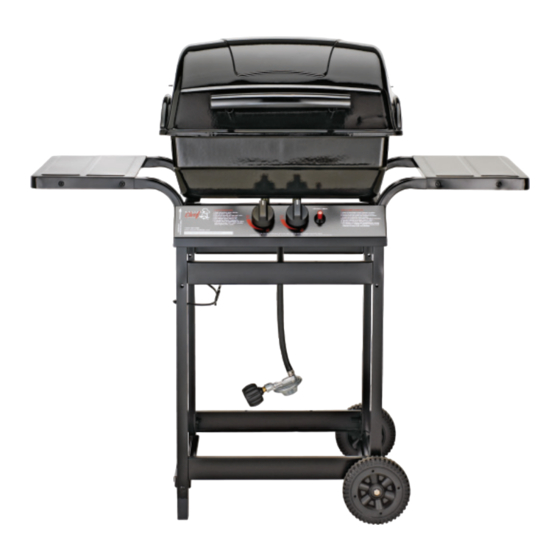
280 Barbeque Assembly Manual 85-3001-8 (G20715) Propane 1 YEAR LIMITED WARRANTY READ AND SAVE MANUAL FOR FUTURE REFERENCE. If pre-assembled, leave this manual with unit for consumer’s future reference. For product inquiries, parts, warranty and troubleshooting support, please call 1-877-707-5463. - Page 3 H E A V Y A R T I C L E N E E D S 2 T O L I F T THIS MANUAL MUST REMAIN WITH THE PRODUCT AT ALL TIMES To ORDER non-warranty replacement parts or accessories, or to register your warranty, please visit us on the web at www.masterchefbbqs.com.
- Page 4 PARTS LIST (PROPANE) FOR 85-3001-8 (G20715) KEY # QUANTITY DESCRIPTION PART NO. Top lid assembly G208-0001-01 Top lid handle G305-0090-01 Upper hinge G206-0002-A1 Burner box assembly G205-0010-02 Lower hinge G206-0010-A1 Cooking grate G206-0006-01 Flame tamer G210-0003-01 Burner G207-2400-01 Collector box...
- Page 5 ASSEMBLY INSTRUCTIONS TWO PEOPLE REQUIRED FOR ALL ASSEMBLY STEPS. a. Front cart assembly: assemble two support braces (DE) to two cart legs (DA) as shown. YOU WILL NEED: FRONT CART ASSEMBLY b. Back cart assembly: assemble two support braces (DE) to the remaining two cart legs (DA), as shown.
- Page 6 ASSEMBLY INSTRUCTIONS a. Position the valve assembly (CD) through the back of the control panel (CA), and assemble. YOU WILL NEED: VIEW FROM THE BACK OF THE CART ASSEMBLY b. Position the control knobs (CB) onto valve stems (CD). c. Assemble the igniter (CC) through the front of the control panel (CA), as shown.
-
Page 7: Side Shelf Assembly
ASSEMBLY INSTRUCTIONS SIDE SHELF ASSEMBLY a. Assemble a side shelf (EA) to the left cart legs (DA), as shown. b. Assemble a side shelf (EA) to the right cart legs (DA), as shown. YOU WILL NEED: RIGHT LEFT BURNER BOX ASSEMBLY a. - Page 8 ASSEMBLY INSTRUCTIONS Assemble the heat shield (BH) to the inside of the left burner box support (DB), as shown. YOU WILL NEED: CAUTION: SHARP EDGES, WEAR SAFETY GLOVES DURING ASSEMBLY Attach the burner electrode wire (BF2) to the igniter (CC).
- Page 9 ASSEMBLY INSTRUCTIONS Position the fl ame tamer (BD) into the burner box assembly (BA). Note: The fl ame tamer (BD) should be placed on to the hardware assembled in Step 7. Position the cooking grate (BC) into the burner box assembly (BA).
Need help?
Do you have a question about the G20715 and is the answer not in the manual?
Questions and answers