Table of Contents
Advertisement
Quick Links
Advertisement
Table of Contents

Related Manuals for Standard Horizon HX891BT


Summary of Contents for Standard Horizon HX891BT
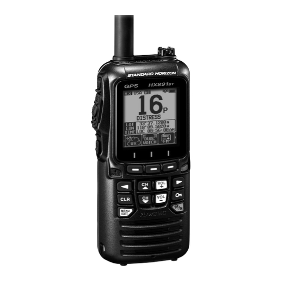
- Page 1 HX891BT HX891BT/E Class-H DSC GPS Transceiver Owner’s Manual...
-
Page 2: Table Of Contents
TABLE OF CONTENTS QUICK REFERENCE ........... 2 9. Bluetooth OPERATION ......33 ® 1. GENERAL INFORMATION ......3 9.1 Pairing the Bluetooth Headset ....... 33 ® 9.2 Bluetooth Headset volume control ....34 1.1 INTRODUCTION ..........3 ® 9.3 Disable Bluetooth Headset function .... - Page 3 14.2 DIMMER ADJUSTMENT ......... 80 17.14 SUMMARY OF THE GPS SETUP ....97 14.3 LAMP ............... 80 18. ATIS SETUP (HX891BT/E only) ....98 14.4 DISPLAY CONTRAST ........81 18.1 ATIS CODE PROGRAMMING ......98 14.5 KEY BEEP ............81 18.2 ATIS CH GROUP ..........
-
Page 4: Quick Reference
QUICK REFERENCE The HX891BT is equipped with the E2O (Easy-To-Operate) menu system. Basic operation may be accomplished by following the procedures below: : Press and hold to turn the transceiver ON/OFF. PTT (Push-To-Talk): Activates the transmitter when pressed. SQL: Press to display the SQL level setting screen, then press the CH▲... -
Page 5: General Information
With the internal high-performance 66 Channel GPS receiver, WAAS and QZSS satellites can be received. We appreciate your purchase of the HX891BT, and encourage you to read this manual thoroughly, so as to learn and fully understand the capabilities of the HX891BT. -
Page 6: Safety Precautions
2. SAFETY PRECAUTIONS Be sure to read the safety precautions, and use this product safely. Yaesu is not liable for any failures or problems caused by the use or misuse of this product by the pur- chaser or any third party. Also, Yaesu is not liable for damages caused through the use of this product by the purchaser or any third party, except in cases where ordered to pay damages under the laws. -
Page 7: Online Warranty Registration
Please visit www.standardhorizon.com - Owner’s Corner to register the HX891BT Marine VHF. NOTE: visiting the STANDARD HORIZON website from time to time may be benefi- cial. When new products are released, information will appear on the website. 4. ABOUT THIS RADIO... -
Page 8: Distress And Hailing (Channel 16)
10. If there is no answer, repeat the above procedure. If there is still no response, try another channel. NOTE The HX891BT has the DSC Distress Alert, that can transmit a Distress Alert digitally to all ships with compatible DSC radios. Refer to section “11. DIGITAL SELECTIVE CALLING (DSC)”. -
Page 9: Calling Another Vessel (Channel 16 Or 9)
CALLING ANOTHER VESSEL (CHANNEL 16 OR 9) Channel 16 may be used for initial contact (hailing) with another vessel. However, its most important use is for emergency messages. This channel must be monitored at all times except when actually using another channel. It is monitored by the U.S. -
Page 10: Making Telephone Calls
MAKING TELEPHONE CALLS To make a radiotelephone call, use a channel designated for this purpose. The fastest way to learn which channels are used for radiotelephone traffic is to ask at a local marina. Channels available for such traffic are designated Public Correspondence channels on the channel charts in this manual. -
Page 11: Notes To Assure Waterproof Integrity
NOTES TO ASSURE WATERPROOF INTEGRITY CAUTION! To ensure the waterproof integrity of the HX891BT, please make sure to observe the precautions described below of the HX891BT, observe the precautions regarding waterproofing as described below. Failure to observe even one of the precautions may degrade the waterproof integrity, resulting in water intrusion into the transceiver. -
Page 12: Packing List
DC Cable with 12 V Cigarette Lighter Plug E-DC-6 DC Cable; plug and wire only SCH-11 Belt Clip Hanger *1(Depending on the transceiver version) NOTE Charge the battery before operating the HX891BT for the first time. Please see section “6.1.4 Battery Charging” for details. -
Page 13: Getting Started
6. GETTING STARTED CAUTION! Waterproof and floating features of the transceiver are assured only when the battery cover is correctly attached to the transceiver, the DATA jack cover is locked completely and the MIC/SP cap is screwed in tight. Refer to the section “4.8 NOTES TO ASSURE WATERPROOF INTEGRITY”, for details on the waterproof and floating integrity. - Page 14 Battery packs should be charged only in non-hazardous environments. Use only STANDARD HORIZON-approved batteries. Use only a STANDARD HORIZON-approved charger. The use of any other charger may cause permanent damage to the battery. Follow charging instructions provided with the chargers.
- Page 15 6.1.2 Rechargeable Battery Installation/Removal 1. Turn the transceiver OFF. 2. Slide the battery cover lock switch to the “UNLOCK” position, then press “PUSH” to open the battery cover. UNLOCK 3. Install the SBR-13LI battery pack into the battery rest aligning it to the battery contacts until it clicks.
- Page 16 NOTE The SBH-32 is only designed for the charging of the HX891BT’s battery, and is not suitable for other purposes. The SBH-32 may contribute noise to TV and radio reception in the immediate vicinity, so we do not recommend...
-
Page 17: Belt Clip Installation / Removal
6.1.5 Installation of the SBT-13 Battery Case The SBT-13 is a battery case that holds five “AAA” size Alkaline batteries and is used with the HX891BT transceiver. The Alkaline batteries can be used for reception and transmission in an emergency, and battery life will be shortened dramatically. -
Page 18: Attaching An Antenna
ATTACHING AN ANTENNA Insert the CAT460 antenna into the ANT jack at the top panel, hold the bottom end of the antenna, then screw it onto the mating connector on the transceiver until it is snug. Do not over-tighten. MARITIME MOBILE SERVICE IDENTITY (MMSI) 6.4.1 What is an MMSI? An MMSI is a nine-digit number used on marine transceivers capable of using Digital Selective Calling (DSC). -
Page 19: Checking Gps Signal (Gps Status Display)
1 to 2. Look that the MMSI number shown on the display is correct. CHECKING GPS SIGNAL (GPS STATUS DISPLAY) When the HX891BT receives the GPS signal, a small satellite icon “ ” will appear on the display and your current location (latitude/longitude) is shown on the display. -
Page 20: Changing The Gps Time
NOTE • When the HX891BT is first turned on, it may take several minutes to compute a fix of your position. This is normal, as the HX891BT is down- loading “almanac” information from the GPS satellites. • When using the HX891BT inside of a cabin where GPS reception is limited, choose a place where GPS satellite reception is good enough referring to the GPS status display. -
Page 21: Controls And Switches
For detailed operating instructions refer to chapter 8 of this manual. NOTE HX891BT is only submersible* when the MIC/SP jack, DATA jack and battery cover, are properly sealed with their rubber gaskets. *(IPX8 Specification for submersibility: 5ft. (1.5m) for 30 minutes.) ANT jack ( Top side ) The supplied CAT460 flexible antenna is attached here. - Page 22 SQL switch (Left side) Press this key to activate the squelch adjusting mode. Press the CH▲ or CH▼ key to adjust the squelch threshold level. Press and hold the squelch key for 3 seconds to open the squelch, allow- ing you to monitor the operating channel. Press this key to resume normal (quiet) monitoring.
- Page 23 VOL+ key Press to increase the speaker audio volume level. VOL− key Press to decrease the speaker audio volume level. 16/S key Pressing this key immediately recalls channel 16 from any channel location. Holding the key down recalls the SUB channel (The default setting is channel 9).
-
Page 24: Basic Operation
8. BASIC OPERATION NOTE Before operating the HX891BT for the first time, it is recommended that you fully charge the battery. See section “6.1.4 Battery Charging”. for details. TURNING THE TRANSCEIVER ON AND OFF 1. Press and hold the key on the left side of the radio to turn the radio ON. -
Page 25: Transmit Time-Out Timer (Tot)
8.3.1 Transmit Power The TX output power of the HX891BT is set to high level (6 W (5 W)*) in factory default, and the “HI” indicator is displayed at the top of the screen. To switch the TX output power: 1. -
Page 26: Selecting The Channel Group
1050 Hz tone and subsequent weather report on one of the NOAA weather channels. The HX891BT can receive weather alerts when monitoring a weather channel and, on the last selected weather channel during scanning modes or while on... -
Page 27: Multi Watch (To Priority Channel)
8.7.2 NOAA Weather Alert Testing (USA version only) NOAA tests the alert system ever Wednesday between 11AM and 1PM. To test the HX891BT’s NOAA weather feature, setup as in section 8.7.1 NOAA Weather Alert (USA version only) and confirm the alert is heard on Wednes- days between 11AM and 1PM local time. -
Page 28: Scanning
LOC 09:56:56 channel that was selected in step 2. If a signal is received on the watch channel selected in step 2, the HX891BT will periodically dual watch to the priority channel. 4. To stop dual watch, press the [◄]/[►] key repeatedly, then press the [DUAL WATCH] soft key again. - Page 29 8.9.1 Selecting the Scan Type SELECT Press and hold SELECT CH SETUP SCAN TYPE key) key) key) key) 1. Press the [CH▼]/[CH▲] key to select “PRIORITY” or CH SETUP SCAN TYPE “MEMORY”. PRIORITY 2. Press the [ENTER] soft key to store the selected setting. MEMORY 3.
-
Page 30: Preset Channels: Instant Access
8.9.3 Memory Scanning (M-SCAN) 1. Set the scan type to “MEMORY” in the CH SETUP menu (refer to “8.9.1 Selecting the Scan Type”). 2. Press the SQL key, then press the [CH▼]/[CH▲] key until background noise disappears. 3. Press the [◄]/[►] key repeatedly, then press the [SCAN] MEM- soft key. -
Page 31: Programming
8.10.1 Programming 1. Press the [CH▼]/[CH▲] key to select the BUSY channel to be programmed. P-SET 2. Press the [◄]/[►] key repeatedly to indicate USCG 33 ° 37.1200 the function on the display, then press and 118 ° 09.5822 BUSY TIME LOC 09:56:56 P-SET... -
Page 32: Listening To The Fm Broadcast Radio
8.11 Listening to the FM Broadcast Radio The HX891BT includes provision for FM broadcast reception. 1. Press the [◄]/[►] key repeatedly, then press the [FM] soft key. 2. The FM radio screen will appear, press the [CH▼]/[CH▲] key to tune the frequency in 100kHz steps. -
Page 33: Mob Operation
VOX headset SSM-64A (or a compatible device from a third-party vender). Insert the plug of the VOX headset into the MIC/SP jack of the HX891BT, then speak into the microphone of the headset to start VOX operation. -
Page 34: Operation Menu
8.15 OPERATION MENU The HX891BT provides the advanced features listed below, via the “MENU” screen that is displayed by pressing the [MENU/ SET] key on the front panel. DSC CALL The following four types of DSC (Digital Selective Calling) are available: Individual Calling;... -
Page 35: Operation
6. Press the [OK] soft key, then [CLR] key to return the transceiver to normal operation. While connected to a Bluetooth headset, the “ ” icon appears on the ® HX891BT screen, and the received audio and operation beep will be heard from the Bluetooth headset. ®... -
Page 36: Bluetooth ® Headset Volume Control
9.2 Bluetooth Headset volume control ® Adjust the volume of the Bluetooth headset with either the [VOL−] / [VOL+] ® button on the HX891BT or the volume control operation of the Bluetooth ® headset. 9.3 Disable Bluetooth Headset function ®... -
Page 37: Connect To Another Paired Bluetooth ® Headset
9.7 Connect to another paired Bluetooth headset ® NOTE: When the HX891BT is already connected to a Bluetooth headset, the ® connection cannot be changed to another headset. First turn OFF the currently connected headset, then try connecting to another headset. -
Page 38: Gps Operation
10. GPS OPERATION The HX891BT has an internal GPS antenna to receive and display the position information. Your position information as well as other station received positions can be stored in memory and utilized later for navigation. NOTE The GPS unit may be turned off, or set to power save mode to increase the battery life, via the SETUP menu. -
Page 39: Gps Logger Operation
10.3 GPS LOGGER OPERATION The HX891BT includes a position logger that allows recording the GPS location information at periodic intervals. 1. Press the [◄]/[►] key repeatedly, then press the [LOGGER] soft key to turn the function ON or OFF. P-SET... -
Page 40: Digital Selective Calling (Dsc)
11.1 GENERAL WARNING This HX891BT is designed to generate a digital maritime distress and safety call to facilitate search and rescue. This unit will only be effective as a safety device, when it is used within communication range of a shore-based VHF marine channel 70 distress and safety watch system (or another vessel equipped with a compatible DCS transceiver).The range of signal may... - Page 41 BACK SELECT Transmitting the Distress Alert by Manually Inputting Location and Time In case the HX891BT fails to get a GPS position fix, you may manually input the latitude and longitude, and the time to transmit the Distress Alert. Press...
- Page 42 When the Distress Alert is transmitted, it is repeated every 4 minutes until the Distress Alert is canceled by the user, or until the radio is turned OFF and ON again. The HX891BT Distress Alert may be suspended (paused) using the procedure below.
-
Page 43: Receiving The Distress Alert
11.2.2 Receiving the Distress Alert 1. When the Distress Alert is received, an emergency alarm RX DISTRESS 366901235 sounds. Yaesu NATURE:UNDESIGNATED 2. Press any key to stop the alarm. 24 ° 25.9755 POS: 118 ° 59.4566 3. Press the CH▼ key several times to show the information 12:56 TIME: NOT ACKNOELESGED... -
Page 44: All Ships Call
11.3 ALL SHIPS CALL The all ships call function permits calling DSC equipped vessels without having their MMSI in the individual calling directory. Also, priority for the call can be designated as “Urgency” or “Safety”. URGENCY Call: This type of call is used when a vessel may not truly be in distress but has a potential problem that may lead to a distress situation. -
Page 45: Receiving An All Ships Call
11.3.2 Receiving an All Ships Call 1. When an all ships call is received, an emer- RX ALL SHIPS 366901234 gency alarm will sound. Yaesu SAFETY CATEG: The display shows the MMSI of the vessel 00:15 SINCE: RX ALL SHIPS transmitting the all ships call and the radio 366901234 Yaesu... -
Page 46: Individual Call
Up to 100 individual contacts may be programmed. 11.4.1 Setting up the Individual Call Directory The HX891BT has a DSC directory that allows you to store a vessel or person’s name and the associated MMSI number you wish to contact via individual calls, position report, and test call transmissions. -
Page 47: Setting Up The Individual Call Reply
8. After the ninth character has been entered, press the [FINISH] soft key. 9. To store the entered data, press the [CH▼] key to select INDIVIDUAL DIR. “SAVE”, then press the [SELECT] soft key. NAME: STANDARD--------- 10. To enter another individual address, repeat steps 1 through MMSI: 987654321 Saved... -
Page 48: Transmitting An Individual Call
11.4.4 Transmitting an Individual Call This feature allows the user to contact another vessel with a DSC radio. This is similar to calling a vessel on CH16 and requesting the operator to go to another working channel. Individual Call using the Individual/Position Directory Press SELECT SELECT... - Page 49 Individual Call by Manually Entering a MMSI An MMSI number to be contacted may be manually entered without storing it in the individual directory. Press SELECT INDIVIDUAL SELECT key) key) key) key) 1. Press the [CH▼]/[CH▲] key to select “NEW INDIVIDUAL CALL HISTORY ID”, then press the [SELECT] soft key.
-
Page 50: Receiving An Individual Call
11.4.5 Receiving an Individual Call When an individual DSC call is received, the radio will automatically respond (default setting) to the calling ship, and switch to the requested channel for voice communications. If you want to see who is calling before replying to the call, change the Call Reply setting to manual. -
Page 51: Setting Up The Individual Call Ringer
2. Press the [ENTER] soft key to store the selected setting. 5sec 10sec 3. Press the [CLR] key to return to radio operation. 15sec 20sec BACK ENTER The HX891BT individual call ringer may be turned ON or OFF. SELECT SELECT DSC SETUP DSC BEEP Press and hold ... -
Page 52: Group Call
MMSI numbers. The first digit of a group MMSI is always set to “0” by International rules. All Standard Horizon radios are preset so when programming a group MMSI the first digit is set to “0”. - Page 53 SELECT SELECT Press and hold DSC SETUP GROUP DIR. key) key) key) key) 1. Begin by entering a name for the group. DSC SETUP GROUP DIR. Press the [SELECT] soft key, then press the [CH▼]/[CH▲] key select “ADD”. EDIT DELETE GROUP DIR.
-
Page 54: Transmitting A Group Call
11.5.2 Transmitting a Group Call Group Call using the Group Directory Press SELECT SELECT GROUP key) key) key) key) 1. Press the [CH▼]/[CH▲] key to select GROUP CALL HISTORY “HISTORY” or “MEMORY”. MEMORY NEW ID 2. Press the [SELECT] soft key, then press GROUP CALL the [CH▼]/[CH▲] key to select a group you HISTORY... -
Page 55: Receiving A Group Call
8. Listen to the channel to make sure it is not busy, then press the PTT button and talk into the microphone to communicate the message to the group of vessels. 11.5.3 Receiving a Group Call 1. When a group call is received, the HX891BT will sound a RX GROUP 036690123 ringing alarm. -
Page 56: Setting Up The Group Call Ringer
You may review the unread group call from the DSC log, refer to the section “11.10.3 Reviewing Other Logged Calls”. 11.5.4 Setting up the Group Call Ringer The HX891BT group call ringer may be set to ON or OFF with the DSC SETUP Menu: SELECT... -
Page 57: Position Request
Advancements in DSC have made it possible to poll the location of another vessel and show the position of that vessel on the display of the HX891BT. This is a great feature for anyone wanting to know the position of another vessel. -
Page 58: Receiving A Position Request
4. When finished entering the MMSI number, press the [FINISH] soft key. 5. Press the [YES] soft key to transmit the position request DSC call. 6. When the HX891BT receives the position from the polled vessel it is shown on the radio display. -
Page 59: Manual Input Of Position Information
“11.10.3 Reviewing Other Logged Calls”. 11.6.3 Manual Input of Position Information If the HX891BT is located in an area where GPS reception is limited, in order to reply to the received position request, you may manually input the location (latitude and longitude) and time to be sent. -
Page 60: Setting Up Position Reply
11.6.4 Setting up Position Reply The HX891BT can be set up to either “automatically” (default setting) or “manu- ally” send your position to another vessel. This selection is important if you are concerned about someone polling the position of your vessel that you may not want to. - Page 61 Press SELECT SELECT POS REPORT key) key) key) key) 1. Press the [CH▼]/[CH▲] key to select POS REPORT CALL HISTORY “HISTORY” or “MEMORY”. MEMORY NEW ID 2. Press the [SELECT] soft key. POS REPORT 3. Press the [CH▼]/[CH▲] key to select the HISTORY KAREN intended recipient in the directory, then...
-
Page 62: Receiving A Dsc Position Report Call
DSC Position Report Call by Manually Input Location and Time If the HX891BT is located in an area where GPS reception is limited and you want to transmit a position report call, you may manually input the location (latitude and longitude) and time to be sent. For details, refer to section “11.6.3 Manual Input of Position Information”. -
Page 63: Saving The Reported Position As A Waypoint
11.7.4 Saving the Reported Position as a Waypoint The HX891BT can save a position report call in the radio’s memory as a waypoint. 1. After the position report call has been RX POS REPORT 987654321 received, press the [SAVE] soft key. -
Page 64: Auto Pos Polling
11.8 AUTO POS POLLING The HX891BT has the capability to automatically track seven vessels programmed into the individual directory, or to automatically send your position information to the programmed stations. 11.8.1 Setting up the Polling Operation SELECT SELECT DSC SETUP... -
Page 65: Enabling/Disabling Auto Pos Polling
1. Press the [CH▼]/[CH▲] key to select AUTO POS POLLING ACTIVATION “SELECTED ID”, then press the [SELECT] SELECTED ID soft key. 2. The radio will show a blank row highlighted AUTO POS POLLING SELECTED ID when you select the vessel for the first time. 1:000000000 BACK SELECT... - Page 66 11.9.1 Programming MMSI into Individual Directory Refer to section 11.4.1 Setting up the Individual Call Directory. 11.9.2 Transmitting a DSC Test to Another Vessel DSC Test call by using Individual/Position Directory Press SELECT DSC TEST SELECT key) key) key)
-
Page 67: Dsc Log Operation
11.9.3 Receiving a DSC Test Call When another vessel transmits a DSC Test call to the HX891BT the following will happen: 1. When a DSC Test call is received, the radio will automati-... - Page 68 11.10.1 Reviewing and Resending a Transmitted Logged Call The HX891BT allows transmitted logged calls to be reviewed and to resend the call. Press SELECT DSC LOG SELECT key) key) key) key) 1. Press the [SELECT] soft key, then confirm...
- Page 69 11.10.3 Reviewing Other Logged Calls Press SELECT DSC LOG SELECT key) key) key) key) 1. Press the [CH▼]/[CH▲] key to select “RX DSC LOG TRANSMITTED OTHER CALL”. RX DISTRESS RX OTHER CALL 2. Press the [SELECT] soft key, then press LOG DELETE the [CH▼]/[CH▲] key to select the station DSC LOG...
-
Page 70: Navigation
12. NAVIGATION The HX891BT is capable of storing up to 250 waypoints for navigation using the compass page. You can also navigate to the DSC Distress Alert GPS position, or to a GPS position received from another DSC radio using DSC polling. -
Page 71: Setting Up Waypoint Directory
2. If you want to give the waypoint an easy-to- WAYPOINT NAME: find name, select “NAME” with the [CH▼]/ 001WPT---------- POSITION: [CH▲] key, press the [SELECT] soft key, -- ° --.---- --- ° --.---- WAYPOINT then enter the name. For details, refer to SAVE POSITION SAVE &... - Page 72 4. When finished editing the position, press the [FINISH] soft key. 5. Select “SAVE” with the [CH▼]/[CH▲] key, then press the [SELECT] soft key to save the mark position into memory. 6. Press the [CLR] key to return to radio operation. Adding a Waypoint SELECT SELECT...
- Page 73 Saving a DSC Position Call as a Waypoint When a position is received from another DSC radio the HX891BT allows the position to be saved as a waypoint. Refer to section “11.7.4 Saving the Reported Position as a Waypoint” for...
-
Page 74: Selecting The Display Range
2. Press the [ENTER] soft key to store the selected setting. BACK ENTER 3. Press the [CLR] key to return to radio operation. 12.1.4 Selecting the Arrival Range This menu item sets the range within which the HX891BT will signal arrival at the destination. Press and hold WAYPOINT SETUP SELECT... -
Page 75: Setting Up Routing Directory
12.2.1 Setting Up Routing Directory NOTE All the destinations and via-points must be programmed as waypoints in the HX891BT memory. Refer to section “12.1.2 Setting Up Waypoint Directory”. Adding a Route WAYPOINT SETUP SELECT SELECT Press and hold ROUTE DIR. - Page 76 Editing a Route This function allows a previously entered route to be edited. WAYPOINT SETUP SELECT SELECT Press and hold ROUTE DIR. key) key) key) key) 1. Press the [CH▼]/[CH▲] key to select WAYPOINT SETUP ROUTE DIR. “EDIT”, then press the [SELECT] soft key.
-
Page 77: Starting And Stopping Route Navigation
12.2.2 Starting and Stopping Route Navigation Press SELECT ROUTE SELECT key) key) key) key) 1. Select the desired category (“HISTORY” or ROUTE HISTORY “MEMORY”), then press the [SELECT] soft key. MEMORY 2. Press the [CH▼]/[CH▲] key to select a route, ROUTE then press the [SELECT] soft key. -
Page 78: Gm Operation
DSC Group call and Auto Position Polling, to display the group members' locations. 13.1 SETTING UP GM OPERATION The HX891BT is capable of storing up to 10 groups with 1 to 9 members each. 13.1.1 Setting Up Group Directory NOTE ●... -
Page 79: Setting Up The Polling Time Interval
6. Press the [CH▼]/[CH▲] key to select a list GM GROUP DIR. number, then press the [SELECT] soft key. STANDARD 7. Press the [CH▼]/[CH▲] key to select a member from the Individual directory, then INDIVIDUAL DIR. YAESU press the [SELECT] soft key. KAREN BACK DELETE... -
Page 80: Starting Gm Operation
13.2 STARTING GM OPERATION SELECT Press key) key) 1. Select a group you want to monitor with the GROUP MONITOR MEMORY [CH▼]/[CH▲] key, then press the [ENTER] KAREN soft key. 366901254 Horizon-1 The GM operation starts and the GM target Standard Horizon-2 USCG... -
Page 81: Starting Navigation To A Group Member
13.2.2 Starting Navigation to a Group Member 1. Press one of the soft keys while the GM target is displayed, then press the [LIST] DW-16 soft key. 300 ° KARENS 2. Press the [CH▼]/[CH▲] key to select a 35.2 NAME 1:KAREN 35.2 N-UP... -
Page 82: Configuration Setup
14. CONFIGURATION SETUP 14.1 DISPLAY MODE The display screen can be set for day time or night time operating. SELECT SELECT Press and hold CONFIGURATION DISPLAY MODE key) key) key) key) CONFIGURATION 1. Press the [CH▼]/[CH▲] key to select the desired LCD DISPLAY MODE screen setting: DAY MODE... -
Page 83: Display Contrast
14.4 DISPLAY CONTRAST The display contrast can be adjusted to suit your operation environment. SELECT SELECT Press and hold CONFIGURATION CONTRAST key) key) key) key) 1. Press the [CH▼]/[CH▲] key to select the CONFIGURATION DIMMER desired contrast from “00” to “30” (“10” is LAMP CONTRAST default). -
Page 84: Strobe Led
14.7 STROBE LED Use this selection to set the emergency strobe LED operation. 14.7.1 Emergency LED SELECT SELECT Press and hold CONFIGURATION STROBE LED key) key) key) key) 1. Press the [CH▼]/[CH▲] key to select CONFIGURATION STROBE LED “EMERGENCY LED”... -
Page 85: Soft Keys
DISPLAY FUNCTION ASSIGNED AS DEFAULT – NONE TX PWR Changes transmit power. 1 (HX891BT) WX/CH Switches channels between weather and marine. SCAN Turns scanning function ON or OFF. DUAL WATCH Turns dual or triple watch scan function ON or OFF. -
Page 86: Key Timer
BACK ENTER *1(The Individual Directory and the GPS Log also eliminated.) *2(HX891BT/E only) 2. Press the [ENTER] soft key to store the selected setting. 3. Press the [CLR] key to return to radio operation. 14.10 SUMMARY OF THE CONFIGURATION SETUP... -
Page 87: Channel Function Setup
This menu item permits setting the channel group to USA, International or Canada maritime channel group assignments. Refer to section “8.6 SELECTING THE CHANNEL GROUP” for details. 15.2 WEATHER ALERT (HX891BT USA version only) Enables/disables the NOAA Weather Alert function. The default setting is “OFF”. SELECT... -
Page 88: Priority Channel
BACK ENTER 15.9 CHANNEL NAME When the HX891BT “Normal” mode is selected, the display will show a name under the channel number. This name describes the use of the channel. The channel names may be customized using the below procedure. -
Page 89: Noise Cancellation
4. Repeat step 2 and 3 until the name is complete. The name can consist of up to 15 characters, if you do not use all 15 characters, select “→” to move to the next space. This method can also be used to enter a blank space in the name. If a mistake was made entering the channel name, press the [CH▼]/[CH▲]/ [◄]/[►] key to select “←”... -
Page 90: Scrambler Setup
15.11 SCRAMBLER SETUP Configure the voice scrambler setting. Two types of voice scrambler functions are available: the 4-code type (CVS2500A compatible) and the 32-code type (FVP-42 compatible for Furuno Electric FM-4721) (The scrambler is not avail- able for CH16 and CH70). SELECT SELECT Press and hold... -
Page 91: Audio Filter Operation
15.12.2 Setting the VOX Level SELECT Press and hold SELECT CH SETUP VOX LEVEL key) key) key) key) CH SETUP 1. Press the [CH▼]/[CH▲] key to select the desired activation VOX LEVEL level. The level can be set from “0” to “4” (“2” is default). 2. -
Page 92: Summary Of The Channel Function Setup
16. DSC SETUP 16.1 INDIVIDUAL DIRECTORY The HX891BT has a DSC directory where the names of vessels or persons, and the associated MMSI that you wish to contact via Individual Calls, Position Requests and Position Report transmissions, may be stored in memory. -
Page 93: Group Directory
Refer to section “11.5.1 Setting up a Group Call” for details. 16.6 POSITION REPLY The HX891BT can be set up to automatically (default setting) or manually send your position when requested by another vessel. This selection is important if you are concerned about someone polling the position of your vessel that you may not want to. -
Page 94: Act (Action) Timer
16.10 NO ACT (ACTION) TIMER If no key is pressed during the “MENU” or “DSC CALL” setup screen, the HX891BT will automatically return to radio operation. The default selection is 15 minutes. SELECT SELECT Press and hold DSC SETUP NO ACT TIMER ... -
Page 95: Gps Setup
POLLING: TEST: 17. GPS SETUP The “GPS Setup” mode allows the parameters for the HX891BT internal GPS unit to be customized for your operating requirements. 17.1 GPS ON/OFF This selection allows the internal GPS unit to be turned ON or OFF to conserve battery power. -
Page 96: Power Save
2. Press the [ENTER] soft key to store the selected setting. 3. Press the [CLR] key to return to radio operation. 17.3 DISPLAY DIRECTION This menu item selects the compass orientation to be shown on the HX891BT display. The default setting is “course up”. SELECT... -
Page 97: Time Offset
1. Press the [CH▼]/[CH▲] key to select “ON” or “OFF”. GPS SETUP PINNING ON: When pinning is turned on, the HX891BT will not update its position unless the vessel travels over 10 Ft. OFF: Whether the vessel is underway or stopped, the HX891BT continuously updates its position. -
Page 98: Sbas (Satellite Based Augmentation System)
3. Press the [CLR] key to return to radio operation. BACK ENTER 17.11 OUTPUT SENTENCES This selection is used to setup the NMEA output sentences of the HX891BT. By default, all the NMEA sentences are turned “OFF”. SELECT SELECT Press and hold OUTPUT SENTENCES ... -
Page 99: Log Erase
17.13 LOG ERASE SELECT SELECT Press and hold LOG ERASE key) key) key) key) GPS SETUP 1. Press the [CH▼]/[CH▲] key to select “CANCEL” or “OK”, LOG ERASE then press the [ENTER] soft key. CANCEL 2. Press the [CLR] key to return to radio operation. BACK ENTER 17.14 SUMMARY OF THE GPS SETUP... -
Page 100: Atis Setup (Hx891Bt/E Only)
ATIS number in memory. 6. Press the [ OK ] soft key to return to radio operation. 18.2 ATIS CH GROUP The HX891BT/E ATIS feature may be enabled or disabled for each channel group. SELECT SELECT... -
Page 101: Maintenance
SELECT 19. MAINTENANCE 19.1 GENERAL The inherent quality of the solid-state components in STANDARD HORIZON radios will provide many years of continuous use. Take the following precau- tions to prevent damage to the radio: • Never key the microphone unless an antenna or suitable dummy load is connected to the transceiver •... -
Page 102: Reset The User Mmsi And Atis Code
19.3 Reset the USER MMSI and ATIS CODE If the MMSI number and ATIS code (HX891BT/E only) need to be reset. Please contact Standard Horizon to obtain the required reset codes. 19.3.1 To request the Reset Code Contact Standard Horizon and confirm the following required information. -
Page 103: Troubleshooting Chart
Poor location for GPS Move to a less obstructed position. satellite reception. Charge indicator does not Defective battery SBR-13LI. Contact Standard Horizon dealer. appear on the display Set the transceiver onto the SBH-32 The transceiver is not set when charging a battery. -
Page 104: Vhf Marine Channel Assignments
20. VHF MARINE CHANNEL ASSIGNMENTS 20.1 HX891BT (USA Version) VHF MARINE CHANNEL CHART CHANNEL USE 160.650 Public Correspondence ( Marine Operator ) 156.050 Port Operation and Commercial. 1001 156.050 VTS in selected areas 160.700 Public Correspondence ( Marine Operator ) 156.100... - Page 105 VHF MARINE CHANNEL CHART CHANNEL USE 2021 – 161.650 CMB Service 157.100 161.700 Port operation, ship movement US Coast Guard Liaison and Maritime Safety Information Broadcasts announced on channel 16 (USA) 1022 157.100 Canadian Coast Guard Liaison and Maritime Safety Information Broadcasts announced on channel 16 (Canada) 161.750 Public Correspondence ( Marine Operator ) 157.150...
- Page 106 VHF MARINE CHANNEL CHART CHANNEL USE ( voice 156.525 Digital selective calling – communications not allowed ) US, Canada: Non-commercial ( Recreational ) , 156.575 International: Port operations and Ship movement Non-commercial ( Inter-ship only ) 156.625 US: Port Operations, Canada: Commercial fishing only, 156.675 International: Inter-ship, Port operations...
-
Page 107: Hx891Bt/E
20.2 HX891BT/E CHANNEL USE SIMPLEX/ TX ( MHz ) LOW PWR All countries ( MHz ) DUPLEX Germany ( Except Germany ) 156.050 160.650 DUPLEX – TELEPHONE NAUTIK 156.100 160.700 DUPLEX – TELEPHONE NAUTIK 156.150 160.750 DUPLEX – TELEPHONE NAUTIK 156.200... - Page 108 CHANNEL USE SIMPLEX/ TX ( MHz ) LOW PWR All countries ( MHz ) DUPLEX Germany ( Except Germany ) 156.825 SIMPLEX – NAUTIK 156.875 SIMPLEX LOW* PORT OPR SHIP-SHIP 156.925 161.525 DUPLEX – INTL NAUTIK 1078 156.925 SIMPLEX – –...
-
Page 109: Specifications
21. SPECIFICATIONS Performance specifications are nominal, unless otherwise indicated, and are subject to change without notice. Measurements are in accordance with TIA/ EIA-603 (U.S.A.) and EN302 885 (EXP). ● GENERAL Frequency Range ........TX: 156.025MHz - 157.425MHz (Frequency differs in some regions) RX: 156.050MHz - 163.275MHz (USA / International, Including WX channels) Channel Spacing .................. - Page 110 ● RECEIVER (for Voice and DSC) Circuit Type .......... Double-Conversion Superheterodyne Intermediate Frequencies ........for Voice 1st: 38.85MHz 2nd: 450kHz for DSC 1st: 30.4MHz 2nd: 450kHz Sensitivity ......... for Voice 0.25 μV for 12 dB SINAD (U.S.A.) -5 dBμ for 20 dB SINAD (EXP) for DSC 0.5 μV for 12 dB SINAD (U.S.A.) 0 dBμ...
-
Page 111: Connecting A Usb Data Terminal To The Pc
22. CONNECTING A USB DATA TERMINAL TO THE PC The HX891BT outputs the following NMEA 0183 sentences 9600: GLL, GGA, GSA, GSV, RMC, DSC and DSE. If you have further inquires, please feel free to contact Product Support at: Phone: (800) 767-2450 Email: marinetech@yaesu.com... -
Page 112: Fcc And Canada Radio License Information
23. FCC AND CANADA RADIO LICENSE INFORMATION Standard Horizon radios comply with the Federal Communication Commission (FCC) and the Innovation, Science and Economic Development Canada (ISED) requirements that regulate the Maritime Radio Service. 23.1 STATION LICENSE An FCC ship station license is no longer required for any vessel traveling in U.S. -
Page 113: Rf Exposure Safety Statement
24. RF EXPOSURE SAFETY STATEMENT 24.1 SAFETY INFORMATION Your wireless handheld portable transceiver contains a low power transmitter. When the Push-to-Talk (PTT) button is pushed, the transceiver sends out radio frequency (RF) signals. In August 1996, the Federal Communications Commission adopted RF exposure guidelines with safety levels for hand-held wireless devices. -
Page 114: Fcc Notice / Ic Notice
25. FCC NOTICE / IC NOTICE NOTICE Unauthorized changes or modifications to this equipment may void compliance with FCC Rules. Any change or modification must be approved in writing by STANDARD HORIZON, a division of YAESU USA. THIS DEVICE COMPLIES WITH PART 15 OF THE FCC RULES. OPERATION IS SUBJECT TO THE FOLLOWING TWO CONDITIONS: ( 1 ) THIS DEVICE MAY NOT CAUSE HARMFUL INTERFERENCE, AND ( 2 ) THIS DEVICE MUST ACCEPT ANY INTERFERENCE RECEIVED, INCLUDING INTERFERENCE THAT MAY CAUSE... - Page 115 CAN ICES-3 (B) / NMB-3 (B) Declaration of Conformity Type of Equipment: Floating Class H DSC Marine Transceiver with GPS Brand Name: STANDARD HORIZON Model Number: HX891BT Manufacturer: YAESU MUSEN CO., LTD. Omori Bell port D building 3F,...
-
Page 116: Standard Horizon Limited Warranty
Limited Warranty is valid only in the country/region where this product was originally purchased. On-line Warranty Registration: Thank you for buying STANDARD HORIZON products! We are confident your new radio will serve your needs for many years! Please register your product at www.standardhorizon.com - Owner’s Corner... - Page 117 We, Yaesu Musen Co. Ltd of Tokyo, Japan, hereby declare that this radio equipment HX891BT/E is in full compliance with EU Radio Equipment Directive 2014/53/EU. The full text of the Declaration of Conformity for this product is available to view at ://www.yaesu.
- Page 118 Copyright 2024 YAESU MUSEN CO., LTD. All rights reserved. No portion of this manual may be reproduced without the permission of YAESU MUSEN CO., LTD. YAESU MUSEN CO., LTD. Omori Bellport Building D-3F 6-26-3 Minami-Oi, Shinagawa-ku, Tokyo, 140-0013, Japan 2404T-AS YAESU USA Printed in Japan 6125 Phyllis Drive, Cypress, CA 90630, U.S.A.
Need help?
Do you have a question about the HX891BT and is the answer not in the manual?
Questions and answers