Table of Contents
Advertisement
Quick Links
Installation, Operation & Maintenance Manual
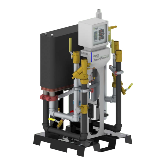
SmartPlate HP
High Pressure Domestic
Hot Water Heaters
Five Double Wall Models:
• SPHPDW38
• SPHPDW54
• SPHPDW72
• SPHPDW116
• SPHPDW175
Disclaimer
The information contained in this manual is subject to change without notice
from AERCO International, Inc. AERCO makes no warranty of any kind with
respect to this material, including, but not limited to, implied warranties of
merchantability and fitness for a particular application. AERCO International is
not liable for errors appearing in this manual, not for incidental or consequential
damages occurring in connection with the furnishing, performance, or use of
these materials
OMM-0142_B
• SP-101 • 5/13/2019
SPHPDW175
SPHPDW38
Advertisement
Table of Contents

Subscribe to Our Youtube Channel
Related Manuals for Watts AERCO SmartPlate HP SPHPDW38


Summary of Contents for Watts AERCO SmartPlate HP SPHPDW38
- Page 1 Installation, Operation & Maintenance Manual SmartPlate HP High Pressure Domestic Hot Water Heaters Five Double Wall Models: • SPHPDW38 • SPHPDW54 • SPHPDW72 • SPHPDW116 • SPHPDW175 SPHPDW175 SPHPDW38 Disclaimer The information contained in this manual is subject to change without notice from AERCO International, Inc.
-
Page 2: Table Of Contents
SmartPlate HP Installation, Operation and Maintenance Manual CONTENTS TABLE OF CONTENTS CHAPTER 1. GENERAL INFORMATION ................5 1.1 INTRODUCTION ........................... 5 1.2 ELECTRONIC CONTROL SYSTEM/SmartPlate HP (ECS/SP) ..............6 1.2.1 Control Box Assembly ........................7 1.2.2 Feed-Forward Temperature Sensors ................... 8 1.2.3 Outlet Temperature Sensors ....................... - Page 3 SmartPlate HP Installation, Operation and Maintenance Manual CONTENTS 6.6 3-WAY CONTROL VALVE OPERATIONAL CHECK ................40 6.7 TEMPERATURE SENSOR CHECKS ....................... 40 6.8 RECIRCULATION PUMP CHECK ......................41 6.9 PERIODIC CLEANING OF HEAT EXCHANGER ..................42 CHAPTER 7. TROUBLESHOOTING ..................43 7.1 INTRODUCTION ..........................
- Page 4 SmartPlate HP Installation, Operation and Maintenance Manual CONTENTS (This Page Is Intentionally Blank) OMM-0142_B • SP-101 • 5/13/2019 Technical Support • (800) 526-0288 • Mon-Fri, 8 am - 5 pm EST Page 4 of 94...
-
Page 5: Chapter 1. General Information
SmartPlate HP Installation, Operation and Maintenance Manual CHAPTER 1 – GENERAL INFORMATION CHAPTER 1. GENERAL INFORMATION 1.1 INTRODUCTION This manual provides detailed coverage for the AERCO SmartPlate HP line of Water-to-Water Heaters. All SmartPlate HP models are equipped with AERCO’s Electronic Control System (ECS), specifically designed for SmartPlate HP (ECS/SP), and an electronic 3-Way Control Valve. -
Page 6: Electronic Control System/Smartplate Hp (Ecs/Sp)
SmartPlate HP Installation, Operation and Maintenance Manual CHAPTER 1 – GENERAL INFORMATION ECS CONTROL BOX AIR BLEEDER 3-WAY VALVE CONTROL VALVE RELIEF VALVE HEAT EXCHANGER MIXING CHAMBER RECIRCULATION DRAIN BOILER WATER DOMESTIC WATER PUMP VALVE INLET STRAINER INLET STRAINER Figure 1-2. SmartPlate HP Components – SPHPDW175 Shown 1.2 ELECTRONIC CONTROL SYSTEM/SmartPlate HP (ECS/SP) Identical Electronic Control Systems are used on all SmartPlate HP models. -
Page 7: Control Box Assembly
SmartPlate HP Installation, Operation and Maintenance Manual CHAPTER 1 – GENERAL INFORMATION DHW OUTLET DUAL TEMP SENSOR RECIRCULATION PUMP FEED-FWD (MIXED WATER) TEMP SENSOR CONTROL BOILER WATER I/O TEMP SENSORS CONTROL VALVE Figure 1-3. Electronic Control System/SmartPlate HP (ECS/SP) Control Box Assembly 1.2.1 The front panel on the Control Box assembly contains all of the display devices for the ECS/SP. -
Page 8: Feed-Forward Temperature Sensors
SmartPlate HP Installation, Operation and Maintenance Manual CHAPTER 1 – GENERAL INFORMATION The Boiler Water inlet and outlet temperatures are sensed on the surface of the inlet/outlet pipes and are provided for informational and troubleshooting purposes only. They are not used for temperature control but they do have alarm limits available for customer settings, if desired. -
Page 9: Smartplate Hp Piping Assemblies
SmartPlate HP Installation, Operation and Maintenance Manual CHAPTER 1 – GENERAL INFORMATION 1.3 SmartPlate HP PIPING ASSEMBLIES All SmartPlate HP models are furnished with a 2” diameter Piping Assembly (see Appendix E for a complete part list). The SmartPlate HP Piping Assembly contains the following components: •... -
Page 10: 3-Way Electronic Control Valve
SmartPlate HP Installation, Operation and Maintenance Manual CHAPTER 1 – GENERAL INFORMATION 1.4 3-WAY ELECTRONIC CONTROL VALVE The 3-Way Electronic Control Valve is powered by 24 VAC from the ECS/SP Control Box. The Temperature Controller in the Control Box supplies a 4 to 20 mA control signal to precisely modulate the 3-Way Valve to accurately control the temperature of the DHW output to the desired setpoint. -
Page 11: Chapter 2. Installation
SmartPlate HP Installation, Operation and Maintenance Manual CHAPTER 2 – INSTALLATION CHAPTER 2. INSTALLATION 2.1 INTRODUCTION All of the SmartPlate HP Water Heater models are shipped fully assembled and ready for installation. Therefore, installation will consist of the following tasks: •... -
Page 12: Site Selection And Preparation
SmartPlate HP Installation, Operation and Maintenance Manual CHAPTER 2 – INSTALLATION 2.3 SITE SELECTION AND PREPARATION Ensure that the site selected for installation of the SmartPlate HP Water Heater includes the following: • Access to AC input power at 120 VAC/60 Hz, 220 VAC/50 Hz or 220 VAC 60 Hz, single phase. -
Page 13: Setting The Unit
SmartPlate HP Installation, Operation and Maintenance Manual CHAPTER 2 – INSTALLATION Setting the Unit 2.3.2 There are several ways to lift and move the unit: • Lift the unit with a forklift under the base. • Position lifting straps through the cutouts in the sides of the base, then lift the unit with a hoist. -
Page 14: Heating Fluid And Domestic Hot Water (Dhw) Piping
SmartPlate HP Installation, Operation and Maintenance Manual CHAPTER 2 – INSTALLATION 2.4 HEATING FLUID AND DOMESTIC HOT WATER (DHW) PIPING The diameter of the heating fluid (hot boiler water) and DHW piping piping for all SmartPlate HP models is 2.0 inches. CAUTION! Two pipe wrenches MUST be used when installing boiler water and DHW piping unions to prevent pipe rotation and avoid leaks. -
Page 15: Electrical Wiring Connections
SmartPlate HP Installation, Operation and Maintenance Manual CHAPTER 2 – INSTALLATION 3-WAY VALVE PLUG Figure 2-3 . SmartPlate HP Lifting Provisions 2.6 ELECTRICAL WIRING CONNECTIONS The SmartPlate HP ECS/SP Control Box and all other ECS/SP components are installed on the unit prior to shipment from the factory. - Page 16 SmartPlate HP Installation, Operation and Maintenance Manual CHAPTER 2 – INSTALLATION ELECTRICAL WIRING CONNECTIONS Instructions 1. Loosen the captive screw on the right-front portion of the Control Box to open the hinged panel door. CAPTIVE PANEL DOOR SCREW HOLE FOR LOCK Figure 2-4.
- Page 17 SmartPlate HP Installation, Operation and Maintenance Manual CHAPTER 2 – INSTALLATION ELECTRICAL WIRING CONNECTIONS Instructions 6. Check the connection of wire #100 on the right side of TB-2 to ensure the power is routed to the proper connection for the 24 VAC transformer. If the incoming power is 120 VAC, wire #100 should be connected to the terminal with a black wire and the orange wire should have nothing connected to its terminal.
- Page 18 SmartPlate HP Installation, Operation and Maintenance Manual CHAPTER 2 – INSTALLATION ELECTRICAL WIRING CONNECTIONS Instructions OVER-TEMPERATURE FAULT RELAY Rated for 2 amps, 260VAC (Energized Upon Fault) Figure 2-7: Remote Relay Option Kit (P/N 69018) Schematic 7. If the ECS was ordered with the Modbus Communication Option, proceed to step 8. However, if this option is not included, no further steps are required.
- Page 19 SmartPlate HP Installation, Operation and Maintenance Manual CHAPTER 2 – INSTALLATION ELECTRICAL WIRING CONNECTIONS Instructions 8. To permit Modbus control of the ECS/SP, refer to Table 2-2, below, and connect the appropriate wire leads to the Temperature Controller terminals listed. Refer to the Temperature Controller (Eurotherm 2408) pinouts shown in Figure 2-8 to locate the required terminals.
-
Page 20: Pressure Relief & Air Bleeder Valve Installation
SmartPlate HP Installation, Operation and Maintenance Manual CHAPTER 2 – INSTALLATION 2.7 PRESSURE RELIEF & AIR BLEEDER VALVE INSTALLATION SmartPlate HP units are shipped with the Pressure Relief Valve and Air Bleeder Valve unassembled. Complete the instructions below to mount them on the Mixing Chamber. Pressure Relief Valve and Air Bleeder Valve Installation Instructions 1. -
Page 21: Chapter 3. Functional Description
SmartPlate HP Installation, Operation and Maintenance Manual CHAPTER 3 – FUNCTIONAL DESCRIPTION CHAPTER 3. FUNCTIONAL DESCRIPTION 3.1 INTRODUCTION SmartPlate HP Water Heaters are equipped with a double-wall, stainless steel brazed plate heat exchanger, an ECS/SP Electronic Control System, and a 3-Way Control Valve. This design results in a highly responsive system which provides virtually constant hot water flow at the selected setpoint temperature. -
Page 22: Electronic Control Overview
SmartPlate HP Installation, Operation and Maintenance Manual CHAPTER 3 – FUNCTIONAL DESCRIPTION 3.3 ELECTRONIC CONTROL OVERVIEW The primary control mechanism for the ECS/SP is an Electronic Process Controller which is installed in the Control Box. The Controller utilizes feed forward and PID (Proportional Integral Derivative) algorithms to provide precise control of the unit’s outlet temperature. - Page 23 SmartPlate HP Installation, Operation and Maintenance Manual CHAPTER 3 – FUNCTIONAL DESCRIPTION 3-way Characterized Valve – responds to hot-water demand (deviation from temperature set- point) & FF temperature Domestic Hot water supply Temperature is compared to Boiler set-point by the Controller Water Inlet Boiler Return Water...
- Page 24 SmartPlate HP Installation, Operation and Maintenance Manual CHAPTER 3 – FUNCTIONAL DESCRIPTION (This Page Is Intentionally Blank) OMM-0142_B • SP-101 • 5/13/2019 Technical Support • (800) 526-0288 • Mon-Fri, 8 am - 5 pm EST Page 24 of 94...
-
Page 25: Chapter 4. Adjustment
SmartPlate HP Installation, Operation and Maintenance Manual CHAPTER 4 – ADJUSTMENT CHAPTER 4. ADJUSTMENT 4.1 INTRODUCTION This chapter provides the adjustment procedures for the 3-Way Control Valve and the SmartPlate HP Electronic Control System (ECS/SP). Prior to shipment from AERCO, all 3-Way Control Valve Actuators are adjusted (auto-stroked) to ensure that they properly position the Control Valve from the fully-open to the fully-closed positions. - Page 26 SmartPlate HP Installation, Operation and Maintenance Manual CHAPTER 4 – ADJUSTMENT 3-WAY VALVE INSTALLATION AND WIRING Instructions MOUNTING BRACKET Figure 4-1. Valve Installation 11. Remove the valve’s black cover to reveal the wiring terminals. Attach the wires to the terminals as shown in the figure below. Figure 4-2.
-
Page 27: 3-Way Valve Stroke Adjustment
SmartPlate HP Installation, Operation and Maintenance Manual CHAPTER 4 – ADJUSTMENT 3-Way Valve Stroke Adjustment 4.2.2 If necessary, the 3-Way Control Valve stroke can be adjusted as follows: 3-WAY CONTROL VALVE STROKE ADJUSTMENT Instructions 1. Apply power and wait for the LED to go off – approximately 10 seconds. 2. -
Page 28: Electronic Control System
SmartPlate HP Installation, Operation and Maintenance Manual CHAPTER 4 – ADJUSTMENT 4.3 ELECTRONIC CONTROL SYSTEM The SmartPlate HP Electronic Control System (ECS/SP) is preset at the setpoint temperature specified on the Sales Order. The over-temperature alarm limit is normally set 20°F above the specified setpoint. - Page 29 SmartPlate HP Installation, Operation and Maintenance Manual CHAPTER 4 – ADJUSTMENT SETPOINT TEMPERATURE ADJUSTMENT Instructions 1. With the Control Box door open, set the ON/OFF power switch on the right side to the ON position. The Temperature Controller will initiate a self-test for approximately 3 seconds. Following the self-test, the top display will show the current outlet water temperature of the unit and the lower display will show the current setpoint temperature stored in memory (default = 140°F).
-
Page 30: Over-Temperature Alarm Limit Adjustment
SmartPlate HP Installation, Operation and Maintenance Manual CHAPTER 4 – ADJUSTMENT SETPOINT TEMPERATURE ADJUSTMENT Instructions When button is pressed, the Controller is toggled between the automatic (AUTO) and manual (MAN) modes. When first set to manual the valve will close and show zero percentage (0 %) on the display. - Page 31 SmartPlate HP Installation, Operation and Maintenance Manual CHAPTER 4 – ADJUSTMENT REPOSITIONING ECS/SP CONTROL BOX Instructions 6. To calibrate the offset (P1), press and hold the SET button for 8 seconds on the Over- Temperature Switch. Access code value 0 is shown in the display. The switch comes from the factory with the code set at 0.
- Page 32 SmartPlate HP Installation, Operation and Maintenance Manual CHAPTER 4 – ADJUSTMENT (This Page Is Intentionally Blank) OMM-0142_B • SP-101 • 5/13/2019 Technical Support • (800) 526-0288 • Mon-Fri, 8 am - 5 pm EST Page 32 of 94...
-
Page 33: Chapter 5. Operation
SmartPlate HP Installation, Operation and Maintenance Manual CHAPTER 5 – OPERATION CHAPTER 5. OPERATION 5.1 INTRODUCTION This chapter provides the pre-operational checks, initial start-up and operating procedures for SmartPlate HP Water Heaters. WARNING! FLUIDS MUST BE GRADUALLY INTRODUCED TO THE UNIT. FAILURE TO DO SO CAN CAUSE DAMAGE TO HEAT EXCHANGER PLATES. -
Page 34: Initial Start-Up
SmartPlate HP Installation, Operation and Maintenance Manual CHAPTER 5 – OPERATION 5.3 INITIAL START-UP In order to prevent a possible over-temperature condition during initial start-up, AERCO recommends that the following steps be performed in the order specified: INITIAL START-UP Instructions 1. -
Page 35: Checking Mixed Inlet Temperature
SmartPlate HP Installation, Operation and Maintenance Manual CHAPTER 5 – OPERATION INITIAL START-UP Instructions PUMP PRIMING SCREW HEAT EXCHANGER Figure 5-1. SmartPlate HP Heat Exchanger – Rear View (SPHPDW38 Shown) 5.4 CHECKING MIXED INLET TEMPERATURE If desired, the water heater mixed inlet temperature can be monitored using the controls and displays on the Temperature Controller. - Page 36 SmartPlate HP Installation, Operation and Maintenance Manual CHAPTER 5 – OPERATION Instructions SHUTTING DOWN THE SYSTEM 1. Turn the power switch on the side of the ECS/SP Control Box to OFF. 2. Close all four of the Isolation Ball Valves. 3.
-
Page 37: Chapter 6. Scheduled Maintenance
SmartPlate HP Installation, Operation and Maintenance Manual CHAPTER 6 – SCHEDULED MAINTENANCE CHAPTER 6. SCHEDULED MAINTENANCE 6.1 INTRODUCTION SmartPlate HP Water Heaters require regular routine maintenance to keep the unit operating at optimum efficiency. AERCO recommends that the tasks listed in Table 6-1 – Scheduled Maintenance Action, be performed at the periodic intervals specified. -
Page 38: Plate Pack Leakage Checks
SmartPlate HP Installation, Operation and Maintenance Manual CHAPTER 6 – SCHEDULED MAINTENANCE BOILER WATER DIFFERENTIAL PRESSURE GAUGE CHECK Instructions 4. If the Gauge still reads in the Red area on the dial, you may have too much boiler water flow through the unit, or the strainer may be clogged. If the strainer has just been cleaned, try reducing the flow rate. -
Page 39: Over-Temp Switch Check
SmartPlate HP Installation, Operation and Maintenance Manual CHAPTER 6 – SCHEDULED MAINTENANCE 6.4 OVER-TEMP SWITCH CHECK Once every 3 months, check the Over-Temp Switch located in the ECS/SP Control Box as follows: OVER-TEMP SWITCH CHECK Instructions 1. Follow the instructions in Section 4.2.4 to lower the Over-Temp setting to approximately 5°F below the present setpoint temperature shown in the lower display of the Temperature Controller. -
Page 40: 3-Way Control Valve Operational Check
SmartPlate HP Installation, Operation and Maintenance Manual CHAPTER 6 – SCHEDULED MAINTENANCE 6.6 3-WAY CONTROL VALVE OPERATIONAL CHECK Refer to Chapter 4, Section 4.2 and recalibrate the 3-Way Control Valve. Also, check the LED indicator to ensure the Valve is functioning correctly. NOTE: To avoid repeated draining of the Water Heater, perform the annual scheduled maintenance checks specified in section 6.9 at the same time. -
Page 41: Recirculation Pump Check
SmartPlate HP Installation, Operation and Maintenance Manual CHAPTER 6 – SCHEDULED MAINTENANCE TEMPERATURE SENSOR CHECKS Instructions 5. Inspect the Sensors for evidence of scale build-up on the stainless-steel sleeve of the Sensors. If necessary, clean the Sensors using a wire brush. 6. -
Page 42: Periodic Cleaning Of Heat Exchanger
SmartPlate HP Installation, Operation and Maintenance Manual CHAPTER 6 – SCHEDULED MAINTENANCE RECIRCULATION PUMP CHECK Instructions 6. Carefully slide the Pump out and rotate to inspect. DO NOT pull on the electrical conduit when removing Pump. 7. If there is evidence of scale build-up, disconnect the conduit and electrical power connections from the Pump. -
Page 43: Chapter 7. Troubleshooting
SmartPlate HP Installation, Operation and Maintenance Manual CHAPTER 7 – TROUBLESHOOTING CHAPTER 7. TROUBLESHOOTING 7.1 INTRODUCTION The troubleshooting procedures provided in this chapter are intended to aid service and maintenance personnel in isolating the most probable cause of a fault in a packaged SmartPlate HP Water Heater. - Page 44 SmartPlate HP Installation, Operation and Maintenance Manual CHAPTER 7 – TROUBLESHOOTING TROUBLESHOOTING PROCEDURES Instructions 4. Continue checking each additional PROBABLE CAUSE for the existing fault until the fault has been corrected. 5. Refer to the applicable procedures in Chapter 8 – Corrective Maintenance if component removal and/or replacement is required.
- Page 45 SmartPlate HP Installation, Operation and Maintenance Manual CHAPTER 7 – TROUBLESHOOTING TABLE 7-1. Troubleshooting – Control Valve and Piping Assembly Fault Indication Probable Cause Corrective Action (Continued) 5. Control Valve is not 5. Check Auto-Stroke to make sure the opening properly. actuator is traveling throughout the complete 90°...
- Page 46 SmartPlate HP Installation, Operation and Maintenance Manual CHAPTER 7 – TROUBLESHOOTING TABLE 7-2. Troubleshooting – Electronic Control System (ECS/SP) Fault Indication Probable Cause Corrective Action System not operating. 1. External 120 VAC 1. Ensure external circuit breaker is ON. power disconnected. Check for 120 or 240 VAC power across All displays are blank.
- Page 47 SmartPlate HP Installation, Operation and Maintenance Manual CHAPTER 7 – TROUBLESHOOTING TABLE 7-2. Troubleshooting – Electronic Control System (ECS/SP) Fault Indication Probable Cause Corrective Action Over-Temp. Alarm 1. Shorted Outlet Temp. 1. Replace Outlet Temp, Sensor. condition cannot be Sensor. cleared.
- Page 48 SmartPlate HP Installation, Operation and Maintenance Manual CHAPTER 7 – TROUBLESHOOTING TABLE 7-2. Troubleshooting – Electronic Control System (ECS/SP) Fault Indication Probable Cause Corrective Action Temperature control not Unexpected system See Table 7-3 for Temperature Control within specifications. dynamics. Troubleshooting. Items T1 –...
- Page 49 SmartPlate HP Installation, Operation and Maintenance Manual CHAPTER 7 – TROUBLESHOOTING TABLE 7-3. Troubleshooting Guide for Temperature Control Issues Observation Probable Cause Corrective Action T9-2 Too wide a deviation in Dynamic loop response Decrease the Proportional value (Pb outlet temperature when time variation from the and/or Pb2) and/or decrease domestic flow changes...
- Page 50 SmartPlate HP Installation, Operation and Maintenance Manual CHAPTER 7 – TROUBLESHOOTING (This Page Is Intentionally Blank) OMM-0142_B • SP-101 • 5/13/2019 Technical Support • (800) 526-0288 • Mon-Fri, 8 am - 5 pm EST Page 50 of 94...
-
Page 51: Chapter 8. Corrective Maintenance
SmartPlate HP Installation, Operation and Maintenance Manual CHAPTER 8 – CORRECTIVE MAINTENANCE CHAPTER 8. CORRECTIVE MAINTENANCE 8.1 INTRODUCTION This chapter provides the procedures to correct and repair faults detected during operation or isolated during troubleshooting of SmartPlate HP Water Heaters. The procedures in this chapter are divided into two sections: •... -
Page 52: Heat Exchanger Cleaning And De-Scaling
SmartPlate HP Installation, Operation and Maintenance Manual CHAPTER 8 – CORRECTIVE MAINTENANCE AIR BLEEDER PRESSURE VALVE RELIEF VALVE BOILER WATER INLET BOILER WATER DHW OUTLET OUTLET COLD WATER INLET ISOLATION BALL ISOLATION VALVES BALL VALVES RECIRCULATION PUMP MIXING CHAMBER DRAIN VALVE Figure 8-1. - Page 53 SmartPlate HP Installation, Operation and Maintenance Manual CHAPTER 8 – CORRECTIVE MAINTENANCE HEAT EXCHANGER REPLACEMENT Instructions 3. Open the Relief Valve to allow air into the pipe during draining. 4. Connect a hose to the Strainer on the Boiler Water side of the piping assembly. Open the valve on the Strainer and drain the boiler water from the unit.
-
Page 54: Control Valve Electronic Actuator Replacement And Valve Removal
SmartPlate HP Installation, Operation and Maintenance Manual CHAPTER 8 – CORRECTIVE MAINTENANCE Control Valve Electronic Actuator Replacement and Valve Removal 8.2.2 The only replaceable item on the 3-Way Control is the Electronics Module. The procedures for removing this Module or replacing the complete Control Valve are provided in sections 8.2.3 and 8.2.4, below. -
Page 55: Control Valve Replacement
SmartPlate HP Installation, Operation and Maintenance Manual CHAPTER 8 – CORRECTIVE MAINTENANCE ELECTRONICS MODULE REPLACEMENT Instructions NUTS (2) VALVE SHAFT ELECTRONICS BOARD DIP SWITCHES ELECTRICAL TERMINALS Figure 8-4. Electronics Module – Cover Removed 8.2.2.2 Control Valve Replacement To remove the complete Control Valve Assembly from the SmartPlate HP Water Heater: CONTROL VALVE REPLACEMENT Instructions 1. -
Page 56: Recirculation Pump Replacement
SmartPlate HP Installation, Operation and Maintenance Manual CHAPTER 8 – CORRECTIVE MAINTENANCE CONTROL VALVE REPLACEMENT Instructions ISOLATION BALL VALVES (2) ISOLATION BALL VALVES (2) DIFFERENTIAL PRESSURE GAUGE 3-WAY CONTROL VALVE BLOW-DOWN VALVE (Connect Drain Hose Here) DRAIN VALVE (Connect Drain Hose Here) Figure 8-5. - Page 57 SmartPlate HP Installation, Operation and Maintenance Manual CHAPTER 8 – CORRECTIVE MAINTENANCE RECIRCULATION PUMP REPLACEMENT Instructions RETURN TO BOILER HOT WATER INLET FROM BOILER COLD WATER INLET ISOLATION BALL VALVES (2) ISOLATION BALL VALVES (2) BOILER WATER INLET STRAINER BLOW DOWN VALVE COLD WATER RECIRCULATION...
-
Page 58: Strainers And Differential Pressure Gauge
SmartPlate HP Installation, Operation and Maintenance Manual CHAPTER 8 – CORRECTIVE MAINTENANCE STRAINERS AND DIFFERENTIAL PRESSURE GAUGE 8.2.4 All SmartPlate HP Water Heater models utilize Combination Strainers and Ball Valve on the boiler side, and a strainer on the DHW side to prevent fouling of the heat exchanger by trapping foreign material before it enters the unit. -
Page 59: Electronic Control System (Ecs/Sp)
SmartPlate HP Installation, Operation and Maintenance Manual CHAPTER 8 – CORRECTIVE MAINTENANCE DIFFERENTIAL PRESSURE GAUGE REPLACEMENT Instructions NOTE: The tube fittings are pass-thru type fittings that allow the tube to slide through the fitting without hitting a stop. Prior to installation, make sure that the replacement Gauge has the same type of fittings. -
Page 60: Control Box Assembly Replacement
SmartPlate HP Installation, Operation and Maintenance Manual CHAPTER 8 – CORRECTIVE MAINTENANCE CONTROL BOX ASSEMBLY REPLACEMENT 8.3.2 If necessary, the complete ECS/SP Control Box Assembly can be removed and replaced as follows: CONTROL BOX ASSEMBLY REPLACEMENT Instructions 1. Loosen the captive screws on the Control Box door and the recessed panel (see Figures 2- 4 and 2-5). -
Page 61: Over-Temperature Switch And Temperature Indicators
SmartPlate HP Installation, Operation and Maintenance Manual CHAPTER 8 – CORRECTIVE MAINTENANCE TEMPERATURE CONTROLLER REPLACEMENT Instructions Figure 8-8. Temperature Controller Installation OVER-TEMPERATURE SWITCH AND TEMPERATURE INDICATORS 8.3.4 The Over-Temperature Switch generates an alarm when the preset temperature limit is exceeded. The two Boiler Water Temperature Indicators are “indicator-only” devices; they do not perform any switching functions. -
Page 62: Vac Step-Down Transformer Replacement
SmartPlate HP Installation, Operation and Maintenance Manual CHAPTER 8 – CORRECTIVE MAINTENANCE OVER-TEMPERATURE SWITCH and TEMPERATURE INDICATOR REPLACEMENT Instructions 1. Open the Control Box door to locate the Switch or Indicator to be replaced. 2. Loosen the captive screw on the recessed panel behind the door. Open the swing-down panel to access the Switch/Indicator wiring connections and panel retaining clips. - Page 63 SmartPlate HP Installation, Operation and Maintenance Manual CHAPTER 8 – CORRECTIVE MAINTENANCE STEP-DOWN TRANSFORMER REPLACEMENT Instructions 3. Disconnect the Transformer wire leads from terminal strips TB-1 and TB-2. 4. Remove the mounting hardware and 24 VAC Transformer from the Control Box. 5.
- Page 64 SmartPlate HP Installation, Operation and Maintenance Manual CHAPTER 8 – CORRECTIVE MAINTENANCE STEP-DOWN TRANSFORMER REPLACEMENT Instructions Figure 8-11. ECS/SP Control Box Assembly 69096 (Sheet 2 of 2) OMM-0142_B • SP-101 • 5/13/2019 Technical Support • (800) 526-0288 • Mon-Fri, 8 am - 5 pm EST Page 64 of 94...
- Page 65 SmartPlate HP Installation, Operation and Maintenance Manual CHAPTER 8 – CORRECTIVE MAINTENANCE STEP-DOWN TRANSFORMER REPLACEMENT Instructions ECS/SP CONTROL BOX ASSEMBLY 69096 PARTS LIST Item Qty. Part No. Description 65082 TRANSFORMER, X075CBA, 120/240 TO 24 VAC 64008 TEMPERATURE INDICATOR CONTROLLER 64056 OVER-TEMP SWITCH/TEMP INDICATOR 60003 ON/OFF SWITCH...
- Page 66 SmartPlate HP Installation, Operation and Maintenance Manual CHAPTER 8 – CORRECTIVE MAINTENANCE (This page left intentionally blank) OMM-0142_B • SP-101 • 5/13/2019 Technical Support • (800) 526-0288 • Mon-Fri, 8 am - 5 pm EST Page 66 of 94...
-
Page 67: Appendix A - Modbus Control And Communication
SmartPlate HP Installation, Operation and Maintenance Manual APPENDIX A – MODBUS CONTROL AND COMMUNICATION APPENDIX A Modbus Control and Communication – TEMPERATURE CONTROLLER (Eurotherm 2408) PROCEDURES MODBUS COMMUNICATION INFORMATION & PROCESS / DIAGNOSTIC ALARM MESSAGES OMM-0142_B • SP-101 • 5/13/2019 Technical Support •... - Page 68 SmartPlate HP Installation, Operation and Maintenance Manual APPENDIX A – MODBUS CONTROL AND COMMUNICATION A.1 Temperature Controller (Eurotherm 2408) Procedures The following sections provide the procedures to add a Modbus Communication board to the Temperature Controller and change communication addresses. A.1.1 Adding a Communication Board to the Temperature Controller Parts Needed: a.
- Page 69 SmartPlate HP Installation, Operation and Maintenance Manual APPENDIX A – MODBUS CONTROL AND COMMUNICATION ADDING A COMMUNICATION BOARD Instructions Up/Down Arrow Page Keys Button Scroll Button Figure A-3 5. The Controller will report a hardware error as indicated in Figure A-3. Press the ▲(up) arrow key located on the right side of the Temperature Controller until “8”...
- Page 70 SmartPlate HP Installation, Operation and Maintenance Manual APPENDIX A – MODBUS CONTROL AND COMMUNICATION A.1.2 Changing the Temperature Controller Communication Addresses NOTE: Refer to the button map at the bottom of the display, Figure A-4, for all panel navigation instructions. Button Map Figure A-4 The Temperature Controller address is defaulted to 1 from the factory.
- Page 71 SmartPlate HP Installation, Operation and Maintenance Manual APPENDIX A – MODBUS CONTROL AND COMMUNICATION 2. Enter 24 using the Up Arrow. The number will flash and display PASS. 3. Scroll to Goto (current value is OPEr) and use the Down Arrow to enter a value of Full.
- Page 72 SmartPlate HP Installation, Operation and Maintenance Manual APPENDIX A – MODBUS CONTROL AND COMMUNICATION 8. Go to the home screen by pressing the Page and Scroll buttons at the same time. 9. Page to the ACCS list and change the code to anything other than 24. The codE number you enter will flash off and then on to 0 to confirm that access is now set to the OPEr...
- Page 73 SmartPlate HP Installation, Operation and Maintenance Manual APPENDIX A – MODBUS CONTROL AND COMMUNICATION A.2 Modbus Communication Information NOTE: The Eurotherm 2400 Controller supports the MODBUS RTU mode of transmission. The default settings are as follows: 9600 Baud Rate, one start bit, eight data bits, one stop bit, & no parity bit.
- Page 74 SmartPlate HP Installation, Operation and Maintenance Manual APPENDIX A – MODBUS CONTROL AND COMMUNICATION A.3 Process & Diagnostic Alarms The Process and Diagnostic Alarms that can appear in the Temperature Controller display are listed in the following Tables. PROCESS ALARMS DISPLAY MEANING _FSL*...
- Page 75 SmartPlate HP Installation, Operation and Maintenance Manual APPENDIX A – MODBUS CONTROL AND COMMUNICATION DIAGNOSTIC ALARMS DISPLAY MEANING WHAT TO DO` Er r 3 Error 3: Watchdog fail Return Controller for repair Error 4: Keyboard failure. Switch power off and then on, without touching any Er r 4 Stuck button or button was of the Controller buttons...
- Page 76 SmartPlate HP Installation, Operation and Maintenance Manual APPENDIX A – MODBUS CONTROL AND COMMUNICATION (This page left intentionally blank) OMM-0142_B • SP-101 • 5/13/2019 Technical Support • (800) 526-0288 • Mon-Fri, 8 am - 5 pm EST Page 76 of 94...
-
Page 77: Appendix B - Ecs/Sp Wiring Diagram And Terminal Block Connections
SmartPlate HP Installation, Operation and Maintenance Manual APPENDIX B – ECS/SP WIRING DIAGRAM APPENDIX B – ECS/SP Wiring Diagram and Terminal Block Connections Drawing Number: 69008-6 rev A OMM-0142_B • SP-101 • 5/13/2019 Technical Support • (800) 526-0288 • Mon-Fri, 8 am - 5 pm EST Page 77 of 94... - Page 78 SmartPlate HP Installation, Operation and Maintenance Manual APPENDIX B – ECS/SP WIRING DIAGRAM OMM-0142_B • SP-101 • 5/13/2019 Technical Support • (800) 526-0288 • Mon-Fri, 8 am - 5 pm EST Page 78 of 94...
-
Page 79: Appendix C - Smartplate Hp Piping Drawings
SmartPlate HP Installation, Operation and Maintenance Manual APPENDIX C – SMARTPLATE-HP PIPING DRAWINGS APPENDIX C – SMARTPLATE HP Piping Drawings Example Installation – 3 Benchmark 6000 units with 2 SmartPlate HP units OMM-0142_B • SP-101 • 5/13/2019 Technical Support • (800) 526-0288 • Mon-Fri, 8 am - 5 pm EST Page 79 of 94... - Page 80 SmartPlate HP Installation, Operation and Maintenance Manual APPENDIX C – SMARTPLATE-HP PIPING DRAWINGS Drawing Number: SD-A-1171 rev A OMM-0142_B • SP-101 • 5/13/2019 Technical Support • (800) 526-0288 • Mon-Fri, 8 am - 5 pm EST Page 80 of 94...
- Page 81 SmartPlate HP Installation, Operation and Maintenance Manual APPENDIX C – SMARTPLATE-HP PIPING DRAWINGS Drawing Number: SD-A-1172 rev A OMM-0142_B • SP-101 • 5/13/2019 Technical Support • (800) 526-0288 • Mon-Fri, 8 am - 5 pm EST Page 81 of 94...
- Page 82 SmartPlate HP Installation, Operation and Maintenance Manual APPENDIX C – SMARTPLATE-HP PIPING DRAWINGS Drawing Number: SD-A-1181 rev A OMM-0142_B • SP-101 • 5/13/2019 Technical Support • (800) 526-0288 • Mon-Fri, 8 am - 5 pm EST Page 82 of 94...
- Page 83 SmartPlate HP Installation, Operation and Maintenance Manual APPENDIX C – SMARTPLATE-HP PIPING DRAWINGS Drawing Number: SD-A-1182 rev A OMM-0142_B • SP-101 • 5/13/2019 Technical Support • (800) 526-0288 • Mon-Fri, 8 am - 5 pm EST Page 83 of 94...
- Page 84 SmartPlate HP Installation, Operation and Maintenance Manual APPENDIX C – SMARTPLATE-HP PIPING DRAWINGS Drawing Number: SD-A-1183 rev A OMM-0142_B • SP-101 • 5/13/2019 Technical Support • (800) 526-0288 • Mon-Fri, 8 am - 5 pm EST Page 84 of 94...
- Page 85 SmartPlate HP Installation, Operation and Maintenance Manual APPENDIX C – SMARTPLATE-HP PIPING DRAWINGS Drawing Number: SD-A-1184 rev A OMM-0142_B • SP-101 • 5/13/2019 Technical Support • (800) 526-0288 • Mon-Fri, 8 am - 5 pm EST Page 85 of 94...
- Page 86 SmartPlate HP Installation, Operation and Maintenance Manual APPENDIX C – SMARTPLATE-HP PIPING DRAWINGS (This Page Is Intentionally Blank) OMM-0142_B • SP-101 • 5/13/2019 Technical Support • (800) 526-0288 • Mon-Fri, 8 am - 5 pm EST Page 86 of 94...
-
Page 87: Appendix D - Dimensional Drawings
SmartPlate HP Installation, Operation and Maintenance Manual APPENDIX D – DIMENSIONAL DRAWINGS APPENDIX D – Dimensional Drawings Drawing Number: AP-A-1049 rev B OMM-0142_B • SP-101 • 5/13/2019 Technical Support • (800) 526-0288 • Mon-Fri, 8 am - 5 pm EST Page 87 of 94... - Page 88 SmartPlate HP Installation, Operation and Maintenance Manual APPENDIX D – DIMENSIONAL DRAWINGS Drawing Number: SD-A-1173 rev A OMM-0142_B • SP-101 • 5/13/2019 Technical Support • (800) 526-0288 • Mon-Fri, 8 am - 5 pm EST Page 88 of 94...
-
Page 89: Appendix E - Part List
SmartPlate HP Installation, Operation and Maintenance Manual APPENDIX E –PART LIST APPENDIX E – Part List SmartPlate HP Models SPHPDW- Item Description Heat Exchanger 28727-1 28727-2 28727-3 28727-4 28727-5 37 * Eurotherm Clone File 69017-29 69017-30 69017-31 69017-32 69017-33 38 * HX Insulation Kit 80104-1 80104-2... - Page 90 SmartPlate HP Installation, Operation and Maintenance Manual APPENDIX E –PART LIST AERCO SmartPlate HP Part List 05/6/2019 International, Inc. Blauvelt, NY 10913 29455-TAB rev B Sheet 2 of 2 OMM-0142_B • SP-101 • 5/13/2019 Technical Support • (800) 526-0288 • Mon-Fri, 8 am - 5 pm EST Page 90 of 94...
- Page 91 SmartPlate HP Installation, Operation and Maintenance Manual APPENDIX E –PART LIST SmartPlate HP Piping Assembly P/N 22340-TAB Item Qty. Part # Description 22357 Mixing Chamber 22335 2" DW, Outlet Manifold 22336-1 2" Boiler Inlet Manifold 22336-2 2" Boiler Outlet Manifold 90147 Close Nipple, 3/4"...
- Page 92 SmartPlate HP Installation, Operation and Maintenance Manual APPENDIX E –PART LIST Item 1 Model Programmed Control Box Part Number Description SPHPDW38 28047-32 SPHPDW54 28047-33 Control Box SPHPDW72 28047-34 69096 Assembly SPHPDW116 28047-35 SPHPDW175 28047-36 Control Box Assembly – P/N 69096 Item # Qty Part # Description 65082...
-
Page 93: Appendix F - Recommended Spare Parts
SmartPlate HP Installation, Operation and Maintenance Manual APPENDIX F –RECOMMENDED SPARE PARTS APPENDIX F – Recommended Spare Parts NOTE Refer to the SmartPlate HP Parts List illustrations in Appendix E for the locations of the recommended and optional spare parts listed below. TABLE F-1. - Page 94 SmartPlate HP Installation, Operation and Maintenance Manual Change Log Date Description Changed By Rev A: Initial release 2/28/2019 Rev B: 5/7/2019 Chris Blair Updated model numbers Rev C: 5/13/2019 Chris Blair Updated graphics and part list (ref DIR 19-40, PIR 1566-1) ©...
Need help?
Do you have a question about the AERCO SmartPlate HP SPHPDW38 and is the answer not in the manual?
Questions and answers