Table of Contents
Advertisement
Installation, Operation, and Maintenance
Upflow/Horizontal and Dedicated Downflow
Gas-Fired, Direct/Non-Direct Vent, Single Stage Condensing
Furnaces with High Efficiency Motor
U U p p f f l l o o w w , , C C o o n n v v e e r r t t i i b b l l e e t t o o
H H o o r r i i z z o o n n t t a a l l R R i i g g h h t t o o r r
H H o o r r i i z z o o n n t t a a l l L L e e f f t t
A951X040BU3SAC
A951X060BU4SAC
A951X080BU4SAC
A951X080CU5SAC
A951X100CU5SAC
A951X120DU5SAC
WARNING
FIRE HAZARD!
Failure to follow this Warning could result in property damage, severe personal
injury, or death.
This Warning applies to installations with a ammable refrigeration system.
The furnace must be powered except for service. The furnace shall be installed
and connected according to installation instructions and wiring diagrams that
are provided with the evaporator coil.
CAUTION
!
COIL REQUIREMENT!
Failure to follow this Caution could result in property damage or personal injury. 4GXC* and
4MXC* coils installed on upflow furnaces in vertical, horizontal left, or horizontal right
orientations without a factory installed metal drain pan shield must use a MAY*FERCOLKITAA
kit. Coils installed on upflow furnaces must have drain pans that are suitable for 400° F
(205°C) or have a metal drain pan shield. Downflow furnaces do not require a metal drain pan
shield or the use of the MAY*FERCOLKITAA kit.
Only qualified personnel should install and service the equipment. The installation, starting up, and servicing of heating, ventilating, and air-conditioning
equipment can be hazardous and requires specific knowledge and training. Improperly installed, adjusted or altered equipment by an unqualified person
could result in death or serious injury. When working on the equipment, observe all precautions in the literature and on the tags, stickers, and labels that
are attached to the equipment.
June 2024
D D o o w w n n f f l l o o w w O O n n l l y y
A951X040BD3SAC
A951X060BD3SAC
A951X080BD4SAC
A951X100CD5SAC
A951X120DD5SAC
S S A A F F E E T T Y Y W W A A R R N N I I N N G G
A A 9 9 5 5 1 1 X X - - S S V V X X 0 0 0 0 1 1 - - 1 1 D D - - E E N N
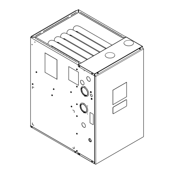
N N o o t t e e : : Graphics in this document are for representation
only. Actual model may differ in appearance.
Advertisement
Table of Contents

Related Manuals for Trane A951X040BD3SAC


Summary of Contents for Trane A951X040BD3SAC
- Page 1 H H o o r r i i z z o o n n t t a a l l R R i i g g h h t t o o r r A951X040BD3SAC H H o o r r i i z z o o n n t t a a l l L L e e f f t t...
- Page 2 SAFETY SECTION — FURNACES I I m m p p o o r r t t a a n n t t : : — This document pack contains a wiring W W A A R R N N I I N N G G diagram and service information.
- Page 3 S S A A F F E E T T Y Y S S E E C C T T I I O O N N — — F F U U R R N N A A C C E E S S W W A A R R N N I I N N G G W W A A R R N N I I N N G G W W A A R R N N I I N N G G ! !
- Page 4 S S A A F F E E T T Y Y S S E E C C T T I I O O N N — — F F U U R R N N A A C C E E S S W W A A R R N N I I N N G G W W A A R R N N I I N N G G E E X X P P L L O O S S I I O O N N H H A A Z Z A A R R D D ! !
- Page 5 S S A A F F E E T T Y Y S S E E C C T T I I O O N N — — F F U U R R N N A A C C E E S S C C A A U U T T I I O O N N C C A A U U T T I I O O N N I I M M P P R R O O P P E E R R V V O O L L T T A A G G E E C C O O N N N N E E C C T T I I O O N N ! !
- Page 6 S S A A F F E E T T Y Y S S E E C C T T I I O O N N — — F F U U R R N N A A C C E E S S C C A A U U T T I I O O N N W W A A R R N N I I N N G G H H O O T T S S U U R R F F A A C C E E ! !
- Page 7 For more information, visit www.trane.com and www.
-
Page 8: Table Of Contents
Table of Contents Accessories....... . . 9 Twinning ....... 56 Document Pack Contents . -
Page 9: Accessories
Accessories Table 1. Accessories Description Model Number Use with B width 4GXCB or 4MCXB Coils when installed with Upflow MAYBFERCOLKITA Heat Shield Kit for B-width 4GXCB or 4MCXB Coils Furnace in all orientations C width 4GXCC or 4MCXC Coils when installed with Upflow MAYCFERCOLKITA Heat Shield Kit for C-width 4GXCC or 4MCXC Coils Furnace in all orientations... -
Page 10: Document Pack Contents
D D o o w w n n f f l l o o w w O O n n l l y y H H o o r r i i z z o o n n t t a a l l R R i i g g h h t t o o r r A951X040BD3SAC Condensate Trap Grommet... -
Page 11: Product Specifications
Product Specifications A951X040BU3SAC A951X060BU4SAC A951X080BU4SAC A951X080CU5SAC MODEL Upflow / Horizontal Upflow / Horizontal Upflow / Horizontal Upflow / Horizontal TYPE RATINGS Input BTUH 40,000 60,000 80,000 80,000 Capacity BTUH (ICS) (c) (d) 39,000 58,300 77,200 77,800 Temp. Rise (Min.-Max.) 30 - 60 30 - 60 45 - 75 40 - 70... - Page 12 P P r r o o d d u u c c t t S S p p e e c c i i f f i i c c a a t t i i o o n n s s A951X100CU5SAC A951X120DU5SAC A951X040BD3SAC A951X060BD3SAC MODEL...
- Page 13 P P r r o o d d u u c c t t S S p p e e c c i i f f i i c c a a t t i i o o n n s s A951X080BD4SAC A951X100CD5SAC A951X120DD5SAC...
-
Page 14: Furnace Installation Guidelines
Furnace Installation Guidelines The following sections give general guidelines for the d. The Furnace input rate and temperature rise installation of the gas furnaces. must be verified to be within the nameplate marking. Safety Practices and Precautions e. A minimum 4” MERV 11 air filter must be in place. -
Page 15: Locations And Clearances
F F u u r r n n a a c c e e I I n n s s t t a a l l l l a a t t i i o o n n G G u u i i d d e e l l i i n n e e s s These furnaces have been classified as CATEGORY IV Bottom 0 in. -
Page 16: Outline Drawing
Outline Drawing Table 2. 17.5”, 21” and 24.5” Upflow Cabinets A951X-SVX001-1D-EN... - Page 17 O O u u t t l l i i n n e e D D r r a a w w i i n n g g Table 3. 17.5”, 21” and 24.5” Downflow Cabinets A951X-SVX001-1D-EN...
-
Page 18: Wiring Diagrams
Wiring Diagrams 120v 60 Hz. 1 PH NOTES: POWER SUPPLY PER LOCAL CODE 1. IF ANY OF THE ORIGINAL WIRING AS SUPPLIED WITH THIS FURNACE MUST BE REPLACED, IT MUST BE WITH WIRE HAVING A A951X TEMPERATURE RATING OF AT LEAST 105°C. WIRES 12, 48, 49, 50, AND 51 REQUIRE A TEMPERATURE RATING OF AT LEAST 250° C. JUNCTION BOX 2. -
Page 19: Airflow Tables
Airflow Tables U U p p f f l l o o w w Furnace Airflow (CFM) Vs. External Static Pressure (in. W.C.) Model SCFM / Watts 510 / 34 314 / 43 118 / 52 SCFM / Watts 532 / 36 341 / 45 150 / 54 SCFM / Watts... - Page 20 178 / 116 SCFM / Watts 827 / 81 691 / 94 554 / 106 418 / 119 281 / 132 A951X040BD3SAC SCFM / Watts 988 / 124 879 / 140 770 / 156 661 / 171 553 / 187...
- Page 21 A A i i r r f f l l o o w w T T a a b b l l e e s s Furnace Airflow (CFM) Vs. External Static Pressure (in. W.C.) Model SCFM / Watts 624 / 47 451 / 57 277 / 68 104 / 79...
-
Page 22: Cfm Versus Temperature Rise
A951X080CU5SAC A951X100CU5SAC A951X120CU5SAC Table 5. Heating Table — Downflow CFM VS. TEMPERATURE RISE CFM (CUBIC FEET PER MINUTE) MODEL 900 1000 1100 1200 1300 1400 1500 1600 1700 1800 1900 2000 2100 2200 2300 A951X040BD3SAC A951X060BD3SAC A951X080BD4SAC A951X100CD5SAC A951X120DD5SAC A951X-SVX001-1D-EN... -
Page 23: Furnace General Installation
Furnace General Installation The following sections give general instructions for the installation of the gas furnaces. Note: For the A951X furnace, a 1/4” nut driver is required to remove the two screws at the top of the front panel. The front panel can then be removed by lifting upwards. -
Page 24: Gas Piping
F F u u r r n n a a c c e e G G e e n n e e r r a a l l I I n n s s t t a a l l l l a a t t i i o o n n Gas Piping Important: When converting the gas piping from the factory default, the plug must be removed from the new gas piping location and swapped with the grommet from the default location. - Page 25 F F u u r r n n a a c c e e G G e e n n e e r r a a l l I I n n s s t t a a l l l l a a t t i i o o n n Horizontal right furnace with gas piping out left side Horizontal right furnace with gas piping out right side The upflow/horizontal furnace is shipped standard for...
-
Page 26: Combustion And Input Check
F F u u r r n n a a c c e e G G e e n n e e r r a a l l I I n n s s t t a a l l l l a a t t i i o o n n Combustion and Input Check Make sure all gas appliances are off except the furnace. -
Page 27: Gas Valve Adjustment
F F u u r r n n a a c c e e G G e e n n e e r r a a l l I I n n s s t t a a l l l l a a t t i i o o n n Gas Valve Adjustment Changes can be made by adjusting the manifold pressure, or changing White-Rodgers 36J... -
Page 28: High Altitude Derate
F F u u r r n n a a c c e e G G e e n n e e r r a a l l I I n n s s t t a a l l l l a a t t i i o o n n High Altitude Derate Input ratings (BTUH) of these Furnaces are based on sea level operation and should not be changed at elevations up to 2,000 ft. -
Page 29: General Venting
F F u u r r n n a a c c e e G G e e n n e e r r a a l l I I n n s s t t a a l l l l a a t t i i o o n n General Venting FURNACE EXHAUST MUST BE VENTED TO THE OUTDOORS. -
Page 30: Typical Venting
F F u u r r n n a a c c e e G G e e n n e e r r a a l l I I n n s s t t a a l l l l a a t t i i o o n n Typical Venting This combustion air intake has a built-in condensate collection Figure 1. -
Page 31: Special Case Venting
F F u u r r n n a a c c e e G G e e n n e e r r a a l l I I n n s s t t a a l l l l a a t t i i o o n n Special Case Venting Special instructions for direct vent furnace air intake. -
Page 32: Vent Terminations
F F u u r r n n a a c c e e G G e e n n e e r r a a l l I I n n s s t t a a l l l l a a t t i i o o n n Vent Terminations For DIRECT VENT APPLICATION: The Furnaces must be vented to Vent terminations... - Page 33 F F u u r r n n a a c c e e G G e e n n e e r r a a l l I I n n s s t t a a l l l l a a t t i i o o n n MANUFACTURED MODULAR VENTING SYSTEMS W W A A R R N N I I N N G G W W A A R R N N I I N N G G...
-
Page 34: Maximum Vent Length Table
Maximum Vent Length Table for Vent and Inlet Air (See Notes) 2 Inch or 2.5 Inch Pipe 3 Inch or 4 Inch Pipe Model Altitude 0–2,000 Feet A951X040BU3SAC, A951X040BD3SAC, A951X060BD3SAC, A951X060BU4SAC A951X080BU4SAC, A951X080BD4SAC, A951X080CU5SAC A951X100CU5SAC, A951X100CD5SAC A951X120DU5SAC, A951X120DD5SAC Note 1 Altitude 2,001–5,400 Feet... -
Page 35: Horizontal Venting
F F u u r r n n a a c c e e G G e e n n e e r r a a l l I I n n s s t t a a l l l l a a t t i i o o n n Horizontal Venting Note: Insure that vent piping is sloped 1/4"... -
Page 36: Horizontal Venting Through Wall
F F u u r r n n a a c c e e G G e e n n e e r r a a l l I I n n s s t t a a l l l l a a t t i i o o n n Table 6. -
Page 37: With Concentric Vent Kit
F F u u r r n n a a c c e e G G e e n n e e r r a a l l I I n n s s t t a a l l l l a a t t i i o o n n Horizontal Venting Through Wall with Concentric Vent Kit These Furnaces may be installed as direct vent (as shipped) or BAYVENT200B / BAYVENTCN200B... - Page 38 The venting system installation instructions can be obtained from the manufacturer by writing to the following address: Trane and American Standard 6200 Troup Highway Tyler, TX 75707...
- Page 39 F F u u r r n n a a c c e e G G e e n n e e r r a a l l I I n n s s t t a a l l l l a a t t i i o o n n Non-Direct Vent Termination Clearances Canadian Installations US Installations...
- Page 40 F F u u r r n n a a c c e e G G e e n n e e r r a a l l I I n n s s t t a a l l l l a a t t i i o o n n Direct Vent Termination Clearances Canadian Installations US Installations...
-
Page 41: Venting Through The Roof
F F u u r r n n a a c c e e G G e e n n e e r r a a l l I I n n s s t t a a l l l l a a t t i i o o n n Venting Through The Roof Support Horizontal pipe every 3’0”... - Page 42 F F u u r r n n a a c c e e G G e e n n e e r r a a l l I I n n s s t t a a l l l l a a t t i i o o n n When penetrating roof with PVC vent pipe, a flexible flashing may be used for a weather tight seal.
-
Page 43: Air For Combustion And Ventilation
F F u u r r n n a a c c e e G G e e n n e e r r a a l l I I n n s s t t a a l l l l a a t t i i o o n n Downward Venting Furnace may be in vertical or horizontal configuration. - Page 44 F F u u r r n n a a c c e e G G e e n n e e r r a a l l I I n n s s t t a a l l l l a a t t i i o o n n •...
-
Page 45: Duct Connections
Duct Connections Air duct systems should be installed in accordance with standards for When the furnace is located in a utility room adjacent to the living air conditioning systems, National Fire Protection Association area, the system should be carefully designed with returns which Pamphlet No. - Page 46 D D u u c c t t C C o o n n n n e e c c t t i i o o n n s s Table 7. Supply Duct Connections Note: The "Coil Requirement" caution is applicable to: C C A A U U T T I I O O N N Upflow furnace with coil, Furnace in horizontal left with coil and...
- Page 47 D D u u c c t t C C o o n n n n e e c c t t i i o o n n s s Table 7. Supply Duct Connections (continued) Furnace in Horizontal Left with Coil Furnace in Horizontal Right with “A”...
- Page 48 D D u u c c t t C C o o n n n n e e c c t t i i o o n n s s Table 7. Supply Duct Connections (continued) Downflow Furnace with Coil Horizontal Right and Downflow Furnace —...
- Page 49 D D u u c c t t C C o o n n n n e e c c t t i i o o n n s s Table 8. Return Duct Connections Return Ducting General Guidelines • Back returns are not allowed on any S-Series Furnaces •...
- Page 50 D D u u c c t t C C o o n n n n e e c c t t i i o o n n s s Table 8. Return Duct Connections (continued) Upflow Furnace with Bottom and Side Returns Mounted on a Ducted Pedestal with Side Return and Filter Box Important: Make sure the condensate and thermostat wiring holes are sealed on the cabinet side with the side return.
- Page 51 D D u u c c t t C C o o n n n n e e c c t t i i o o n n s s Table 8. Return Duct Connections (continued) Upflow Furnace with Two Side Returns Downflow Furnace with Top Return Important: One of the sides must have a transition to allow the condensate and thermostat wiring to exit the cabinet.
- Page 52 D D u u c c t t C C o o n n n n e e c c t t i i o o n n s s I I n n s s t t a a l l l l a a t t i i o o n n I I n n s s t t r r u u c c t t i i o o n n s s 13.
-
Page 53: Return Air Filters
Return Air Filters TYPICAL UPFLOW RETURN AIR FILTER INSTALLATIONS Filters are not factory supplied for upflow furnaces. Filter size needed Upflow Return Air Filters will be dependent on type of filter and CFM requirement. Filters must be installed externally to the unit. Furnace Width Filter Qty and Size... - Page 54 R R e e t t u u r r n n A A i i r r F F i i l l t t e e r r s s RETURN AIR FILTERS FOR MODULAR BLOWER IN Figure 4. Remote Filter Installation HORIZONTAL CONFIGURATION When the modular blower is installed in the horizontal configuration, the return air filters must be installed exterior to the modular blower...
-
Page 55: Electrical Connections
Electrical Connections Make wiring connections to the unit as indicated on enclosed wiring diagram. As with all gas appliances using electrical power, this furnace shall be connected into a permanently live electric circuit. It is recommended that furnace be provided with a separate "circuit protection device" electric circuit. -
Page 56: Twinning
E E l l e e c c t t r r i i c c a a l l C C o o n n n n e e c c t t i i o o n n s s Twinning NOTES: 1. -
Page 57: Condensate Drain Instructions
Condensate Drain Instructions The following sections give general instructions for the C C A A U U T T I I O O N N installation of the gas furnace condensate drains. W W a a t t e e r r D D a a m m a a g g e e / / P P r r o o p p e e r r t t y y D D a a m m a a g g e e ! ! Repositioning of the condensate trap is covered in the I I t t i i s s r r e e c c o o m m m m e e n n d d e e d d t t h h a a t t a a d d r r a a i i n n p p a a n n b b e e i i n n s s t t a a l l l l e e d d exhaust air options section. -
Page 58: Vertical Applications
C C o o n n d d e e n n s s a a t t e e D D r r a a i i n n I I n n s s t t r r u u c c t t i i o o n n s s Vertical Applications VERTICAL APPLICATIONS Note: For easiest installation, remove the spring clip from the end of... - Page 59 C C o o n n d d e e n n s s a a t t e e D D r r a a i i n n I I n n s s t t r r u u c c t t i i o o n n s s Downflow furnace - Cut the 90 degree section of the condensate tubing off and connect the tubing to the condensate trap.
- Page 60 C C o o n n d d e e n n s s a a t t e e D D r r a a i i n n I I n n s s t t r r u u c c t t i i o o n n s s Attaching the condensate drain line.
-
Page 61: Horizontal Applications
C C o o n n d d e e n n s s a a t t e e D D r r a a i i n n I I n n s s t t r r u u c c t t i i o o n n s s Horizontal Applications HORIZONTAL APPLICATIONS Upflow models in horizontal - It is always recommended that the... -
Page 62: General Start-Up And Adjustment
General Start-up and Adjustment The following sections give instructions for the general start-up and adjustment of the gas furnaces. Preliminary Inspections With gas and electrical power "OFF", ensure: Turn knob on main gas valve within the unit to the "OFF" position. Turn the external gas valve to "ON". -
Page 63: Options
Furnace Combustion Air Exhaust Options Important: All plugs must be in place for sealed combustion. Note: If the electrical and natural gas connections are moved to the right side, remove the plugs and move them to the left side. Note: Default is left side for electric and natural gas connections. The grommets will move from the left side to the right side. - Page 64 F F u u r r n n a a c c e e C C o o m m b b u u s s t t i i o o n n A A i i r r E E x x h h a a u u s s t t O O p p t t i i o o n n s s Table 11.
-
Page 65: Upflow Position - Top Vented
F F u u r r n n a a c c e e C C o o m m b b u u s s t t i i o o n n A A i i r r E E x x h h a a u u s s t t O O p p t t i i o o n n s s Upflow Position - Top Vented N N o o t t e e : : The vent outlet adapter is used for strain relief against the weight of the venting. - Page 66 F F u u r r n n a a c c e e C C o o m m b b u u s s t t i i o o n n A A i i r r E E x x h h a a u u s s t t O O p p t t i i o o n n s s 6.
- Page 67 F F u u r r n n a a c c e e C C o o m m b b u u s s t t i i o o n n A A i i r r E E x x h h a a u u s s t t O O p p t t i i o o n n s s N N o o t t e e : : If required, transition to larger venting within 2' of the cabinet.
-
Page 68: Horizontal Left Position - Top Vented
F F u u r r n n a a c c e e C C o o m m b b u u s s t t i i o o n n A A i i r r E E x x h h a a u u s s t t O O p p t t i i o o n n s s Horizontal Left Position - Top Vented Combustion Air Changes need to be made to the inducer orientation... - Page 69 F F u u r r n n a a c c e e C C o o m m b b u u s s t t i i o o n n A A i i r r E E x x h h a a u u s s t t O O p p t t i i o o n n s s 10.
- Page 70 F F u u r r n n a a c c e e C C o o m m b b u u s s t t i i o o n n A A i i r r E E x x h h a a u u s s t t O O p p t t i i o o n n s s 24.
-
Page 71: Furnace In Horizontal Left Position - Side Vented Combustion Air
F F u u r r n n a a c c e e C C o o m m b b u u s s t t i i o o n n A A i i r r E E x x h h a a u u s s t t O O p p t t i i o o n n s s Furnace in Horizontal Left Position - Side Vented Combustion Air Changes do not need to be made to the inducer... - Page 72 F F u u r r n n a a c c e e C C o o m m b b u u s s t t i i o o n n A A i i r r E E x x h h a a u u s s t t O O p p t t i i o o n n s s 13.
-
Page 73: Furnace In Horizontal Right Position - Top Vented Combustion Air
F F u u r r n n a a c c e e C C o o m m b b u u s s t t i i o o n n A A i i r r E E x x h h a a u u s s t t O O p p t t i i o o n n s s I I m m p p o o r r t t a a n n t t : : Trim the pressure switch tubing to length to Before proceeding, lay unit on its back to make the ensure there is no sag or trap created. - Page 74 F F u u r r n n a a c c e e C C o o m m b b u u s s t t i i o o n n A A i i r r E E x x h h a a u u s s t t O O p p t t i i o o n n s s 11.
- Page 75 F F u u r r n n a a c c e e C C o o m m b b u u s s t t i i o o n n A A i i r r E E x x h h a a u u s s t t O O p p t t i i o o n n s s N N o o t t e e : : If required, transition to larger venting within 2' of the cabinet.
-
Page 76: Furnace In Horizontal Right Position - Left Vented Combustion Air
F F u u r r n n a a c c e e C C o o m m b b u u s s t t i i o o n n A A i i r r E E x x h h a a u u s s t t O O p p t t i i o o n n s s 3. - Page 77 F F u u r r n n a a c c e e C C o o m m b b u u s s t t i i o o n n A A i i r r E E x x h h a a u u s s t t O O p p t t i i o o n n s s 16.
- Page 78 F F u u r r n n a a c c e e C C o o m m b b u u s s t t i i o o n n A A i i r r E E x x h h a a u u s s t t O O p p t t i i o o n n s s 26.
-
Page 79: Downflow Furnace - Top Vented
F F u u r r n n a a c c e e C C o o m m b b u u s s t t i i o o n n A A i i r r E E x x h h a a u u s s t t O O p p t t i i o o n n s s I I m m p p o o r r t t a a n n t t : : Cut to length to ensure there is no sag or trap created. -
Page 80: Downflow Furnace - Left Side Vented
F F u u r r n n a a c c e e C C o o m m b b u u s s t t i i o o n n A A i i r r E E x x h h a a u u s s t t O O p p t t i i o o n n s s Before proceeding, lay unit on its back to make conversion easier. - Page 81 F F u u r r n n a a c c e e C C o o m m b b u u s s t t i i o o n n A A i i r r E E x x h h a a u u s s t t O O p p t t i i o o n n s s 7.
- Page 82 F F u u r r n n a a c c e e C C o o m m b b u u s s t t i i o o n n A A i i r r E E x x h h a a u u s s t t O O p p t t i i o o n n s s I I m m p p o o r r t t a a n n t t : : Trim the condensate pressure switch tubing to length to ensure there is no sag or trap created.
-
Page 83: Integrated Furnace Control Menu
Integrated Furnace Control Menu A951X Control System Menu Single Stage OD Example Example Gas Heat Tap 5 SETTING UP YOUR SYSTEM: To change any factory default value, first remove any Status Menu “call” from the furnace and allow all fan off delays to finish. - Page 84 I I n n t t e e g g r r a a t t e e d d F F u u r r n n a a c c e e C C o o n n t t r r o o l l M M e e n n u u A951X-SVX001-1D-EN...
-
Page 85: Belly Band Location
Distance from belly band to the back side off motor for minimum vibration Dimension “A” (inches) Furnace Model Number A951X060BU4SAC 2.65 A951X080BU4SAC A951X080BD4SAC 3.54 A951X100CU5SAC 3.81 A951X040BU3SAC A951X040BD3SAC A951X060BD3SAC A951X080CU5SAC 3.91 A951X100CD5SAC A951X120DU5SAC A951X120DD5SAC Blower housings and wheel removed from view for clarity. A951X-SVX001-1D-EN... -
Page 86: Setting Airflow
Setting Airflow With all ductwork connected and a clean filter in place, measure the External Static Pressure (ESP) of the unit in locations below. Use the appropriate airflow table in the Airflow Tables section for the furnace and outdoor unit installed. Evaporator Measurements must be made prior to the evaporator coil, if equipped, Coil... -
Page 87: Codes
Integrated Furnace Control Display Codes Menu Options Idle Active Alarm Errors Last 6 Faults (To clear — Hold Option button down for 5 seconds after entering the L6F menu) Code Release Number Cooling Off Delay (Seconds) Outdoor Unit Type Blower Constant Fan Airflow Heat Off Delay (Seconds) Gas Heating CFM Run Test Mode... -
Page 88: Fault Code Recovery
I I n n t t e e g g r r a a t t e e d d F F u u r r n n a a c c e e C C o o n n t t r r o o l l D D i i s s p p l l a a y y C C o o d d e e s s Fault Code Recovery Fault Code Recovery To view the last 6 faults, press the “Menu”... -
Page 89: Troubleshooting
Troubleshooting The following pages include troubleshooting ONLY qualified technicians should attempt to install, flowcharts in reference to the A951X single stage troubleshoot, or repair this appliance. furnaces only Failure to follow all cautions and/or warnings could The information contained is for reference only and result in personal or property damage, including death. - Page 90 T T r r o o u u b b l l e e s s h h o o o o t t i i n n g g A951X IFC Component Layout LINE Neutral Inducer/Igniter Connections Connections Connector 6 Pin CTM Connector IGN-N...
- Page 91 T T r r o o u u b b l l e e s s h h o o o o t t i i n n g g GETTING STARTED Is 120 VAC Is the IFC Seven Is 120 VAC Is 120 VAC measured measured Segment LED on?
- Page 92 T T r r o o u u b b l l e e s s h h o o o o t t i i n n g g DEFINITION 2.1 Fault Code RETRY Lock Out = 3 unsuccessful tries for igni on within a single call for heat.
- Page 93 T T r r o o u u b b l l e e s s h h o o o o t t i i n n g g DEFINITION 2.2 Fault Code RECYCLE Lock Out = 10 recycles within a single call for heat.
- Page 94 T T r r o o u u b b l l e e s s h h o o o o t t i i n n g g DEFINITION Gas Valve not energized when it should 2.3 Fault Code be 10 times within the same call for heat.
- Page 95 T T r r o o u u b b l l e e s s h h o o o o t t i i n n g g DEFINITION Note #1 An error has occurred with the PS1 indica ng that the pressure switch is either open when it should be closed.
- Page 96 T T r r o o u u b b l l e e s s h h o o o o t t i i n n g g See next page for DEFINITION 4.0 Fault Code addi onal 4 flash Limit switches are safety devices faults that will open when an abnormal...
- Page 97 T T r r o o u u b b l l e e s s h h o o o o t t i i n n g g DEFINITION 4.0 Fault Code Limit switches are safety devices Flame Rollout that will open when an abnormal high temperature has been sensed.
- Page 98 T T r r o o u u b b l l e e s s h h o o o o t t i i n n g g DEFINITION 5.0 Fault Code Flame is sensed when it should not be sensed. Disconnect electrical power to furnace Turn off...
- Page 99 T T r r o o u u b b l l e e s s h h o o o o t t i i n n g g DEFINI Polarity Fault – Incoming high voltage 6.1 Fault Code wiring is reversed Connect volt meter to white incoming...
- Page 100 T T r r o o u u b b l l e e s s h h o o o o t t i i n n g g DEFINITION : Igniter Relay Fault – The control board has sensed 6.3 Fault Code that the igniter relay has stuck closed Ignitor Fault –...
- Page 101 T T r r o o u u b b l l e e s s h h o o o o t t i i n n g g DEFINITION: External Gas Valve 7.1 Fault Code Circuit Error (24 volts is present when it should not be present) Turn Comfort Control to “OFF”...
- Page 102 T T r r o o u u b b l l e e s s h h o o o o t t i i n n g g DEFINITION: 08 Fault Code The flame sense current is less than 0.5 micro-amp DC Make a call for hea ng...
- Page 103 T T r r o o u u b b l l e e s s h h o o o o t t i i n n g g Defini on: Condensate Pressure Switch Open: The 09 Fault Code condensate system is free flowing and opened the safety switch OR Inducer Limit: This error is normally caused by...
- Page 104 T T r r o o u u b b l l e e s s h h o o o o t t i i n n g g 11 Fault Code Defini on: The IFC has detected that internal gas valve relays have failed.
- Page 105 T T r r o o u u b b l l e e s s h h o o o o t t i i n n g g DEFINITION: E14 / E18 Fault Code These errors has been reported in associa on with the S9X2 model furnaces on ini al start-up.
-
Page 106: Sequence Of Operation
Sequence of Operation G G a a s s H H e e a a t t i i n n g g 8. Once flame sense has been established, a timer on the IFC starts, and the indoor blower will energize 1. -
Page 107: Periodic Servicing Requirements
Periodic Servicing Requirements 1. GENERAL INSPECTION – E E x x a a m m i i n n e e t t h h e e f f u u r r n n a a c c e e N N o o t t e e : : Be careful NOT to break igniter when removing i i n n s s t t a a l l l l a a t t i i o o n n a a n n n n u u a a l l l l y y f f o o r r t t h h e e f f o o l l l l o o w w i i n n g g i i t t e e m m s s : : burners. - Page 108 About Trane and American Standard Heating and Air Conditioning Trane and American Standard create comfortable, energy efficient indoor environments for residential applications. For more information, please visit www.trane.com or www.americanstandardair.com. The manufacturer has a policy of continuous data improvement and it reserves the right to change design and specifications without notice. We are committed to using environmentally conscious print practices.
Need help?
Do you have a question about the A951X040BD3SAC and is the answer not in the manual?
Questions and answers