Table of Contents
Advertisement
Quick Links
Advertisement
Table of Contents

Related Manuals for MiTAC TYAN GC73A-B8046


Summary of Contents for MiTAC TYAN GC73A-B8046
- Page 1 GC73A-B8046 Service Engineer’s Manual http://www.tyan.com...
- Page 2 MITAC retains the right to make changes to produce descriptions and/or specifications at any time, without notice. In no event will MITAC be held liable for any direct or indirect, incidental or consequential damage, loss of use, loss of data or other malady resulting from errors or inaccuracies of information contained in this document.
- Page 3 FCC Declaration ● Notice for the USA Compliance Information Statement (Supplier's Declaration of Conformity, SDoC) FCC Part 15: This device complies with part 15 of the FCC Rules. This device complies with Part 15 of the FCC Rules. Operation is subject to the following conditions: ‧This device may not cause harmful interference.
- Page 4 Warning This equipment is compliant with Class A of CISPR 32. In a residential environment this equipment may cause radio interference. CAUTION Lithium battery included with this board. Do not puncture, mutilate, or dispose of battery in fire. There will be danger of explosion if battery is incorrectly replaced. Replace only with the same or equivalent type recommended by manufacturer.
- Page 5 This manual is intended for technicians, authorized service personnel or trained hardware service personnel with hardware knowledge of computers. This manual is aimed to provide you with instructions on installing your TYAN GC73A-B8046. How this guide is organized This guide contains the following parts:...
- Page 6 Safety and Compliance Information Before installing and using TYAN GC73A-B8046, take note of the following precautions: ·Read all instructions carefully. ·Do not place the unit on an unstable surface, cart, or stand. ·Do not block the slots and opening on the unit, which are provided for ventilation.
- Page 7 Safety Information Retain and follow all product safety and operating instructions provided with your equipment. In the event of a conflict between the instructions in this guide and the instructions in equipment documentation, follow the guidelines in the equipment documentation. Observe all warnings on the product and in the operating instructions.
- Page 8 General Precautions · Follow all caution and warning instructions marked on the equipment and explained in the accompanying equipment documentation. Machine Room Environment · This device is for use only in a restricted access location, such as a machine room or IT room. ·...
- Page 9 from the horizontal. · Make sure the rack is properly secured to the floor or ceiling. · Make sure the stabilizing feet are attached to the rack if it is a single-rack installation. · Make sure racks are coupled together if it is a multiple-rack installation. ·...
- Page 10 Equipment Power Cords · Use only the power cords and power supply units provided with your system. The system might have one or more power cords. · Plug the power cord into a grounded (earthed) electrical outlet that is easily accessible at all times.
- Page 11 modified. Equipment Repairs and Servicing · The installation of internal options and routine maintenance and service of this product should be performed by technicians, authorized service personnel or trained hardware service personnel who are knowledgeable about the procedures, precautions, and hazards associated with equipment containing hazardous energy levels.
- Page 12 安全資訊 請保留和遵守隨本設備提供的所有產品安全與操作說明。本指南的說明與設 備文件的說明內容如有沖突,請遵守設備文件中的指導。 遵守產品上和操作說明中的所有警告。為降低人身傷害、電擊、火災及設備 損壞的風險,請遵守本指南中包括的所有注意事項。 在安裝、操作和維修產品之前,您必須先熟悉本指南中的安全資訊。 設備上的符號 警告: 該符號表示可能存在危險。如果未遵守注意事項, 則可能出現傷害。請查閱設備文件了解詳細資訊。 請於以下網站讀取電子手冊。 https://www.tyan.com/ 警告: 該符號表示可能存在危險的移動風扇葉片。 請保 持身體部位遠離移動中的風扇葉片。 警告: 該符號表示表面或元件高溫。如果接觸到表面,則 可能被燙傷。為降低被高溫元件燙傷的風險,請在 接觸之前先讓表面溫度冷卻下來。 警告: 該符號表示存在高壓電路或電擊危險。所有維修工 作應交由專業人員。 警告: 維修前須切斷所有電源。 http://www.tyan.com...
- Page 13 一般注意事項 遵守設備上標示的以及隨附設備文件中介紹的所有注意事項和警告資訊。 機房環境 本裝置僅適用於機房或資訊室。 確保系統安裝的區域通風良好,溫度濕度等可控制。 確保機房電源的電壓和頻率與設備電力標籤上標示的電壓和頻率相符。 安裝系統時應遠離高壓、排氣管、散熱器等。 切勿在潮濕環境中使用本產品。 設備底座 請勿堵塞或蓋住系統的槽孔。 切勿將任何物件插入設備的槽孔。內部可能存在高壓。 可導電的物件可能造成短路並引起火災、電擊或設備損壞。 雙膝彎曲,用雙手提起設備。 設備機架 避免人身傷害或設備損壞指引: 遵守當地的職業健康和安全規定以及手工物料搬運的指導。 請勿嘗試獨自搬動機架,搬動機架至少需要兩人。 請勿嘗試搬動滿載的機架。從機架上卸下設備後再搬動它。 請勿嘗試在大於 10 度的斜坡上搬動機架,以免造成危險。 確保機架已正確固定到地板或天花板上。 如果是單機架安裝,確保穩定支腳已裝到機架。 如果是多機架安裝,確保各機架已咬合在一起。 ...
- Page 14 確保機架的全部重量放在承重腳上。 務必從下至上裝入機架。先在機架中裝入最重的元件。 從機架中拉出元件之前,確保機架是水平和穩定的。 確保一次只有一個元件被伸展。如果一次伸展一個以上的元件,則機架可 能會不穩定。 避免設備損壞指引: 機架寬度和深度必須保證能夠適當地進行維修和排列纜線。 保證機架內的通風良好。安裝不當或通風不良可能會損壞設備。 機架不能有實心或受限制的通風門。您必須在機架前後使用絲網門,或者 將門卸下以保證系統的良好通風。 如果您在機架中安裝設備,請勿將設備放在裝置上。這會造成通風不暢, 並可能會造成設備損壞。 確保產品與護欄正確咬合。與護欄咬合不良的產品可能會不穩定。 驗證為機架提供電源的交流電源分支電路沒有多載, 以降低人身傷害、 電擊、火災及設備損壞的風險。 機架總負載不應超過分支電路額定值的 80%。請向對您的設備連線和安 裝規定具有管轄權限的電力部門查詢。 設備電源線 只使用隨系統提供的電源線和電源裝置。系統可能配有一條或多條電源 線。 將電源線插入到能方便接觸到的接地電源插座。 在歐洲供電環境中,您必須將電源線上的綠色/ 黃色接頭接地。如果沒有 將綠色/黃色接頭接地,則可能由於大量電流洩露而造成電擊。 請勿在交流電源線或纜線上放置物件。將電源線或纜線放在人們不易踩到...
- Page 15 請勿拉扯電源線或纜線。從電源插座上斷開電源線時,應抓住電源線插 頭。 為降低電擊風險,請在維修裝置之前,斷開所有電源線連接。 設備電池 本系統使用鋰錳電池。如果電池組處理不當,則會有起火風險。 請勿拆解、擠壓、穿刺電池,將其投入火中或水中,或使其與外部短路接 觸。 請勿將電池置於 60 F) 以上的高溫環境中。 C (140 ° ° 系統電池不可變更。如果更換不正確的電池,則會有爆炸危險。請換上專 為本產品指定的備用電池。 請勿嘗試給電池充電。 按照製造商的說明處理用過的電池。請勿將電池當作一般家庭垃圾處理。 若要對電池進行回收再用或正確處理,請使用公共收集系統,或將其送回授 權合作夥伴或其代理。 警告: 若置換不同型式之電池有起火或爆炸風險。請換上專為本產 品指定的備用電池。 設備改造 不要對本設備進行機械或電氣修改, 以免造成安全問題。對於被改造設備 的認證合格概不負責。 設備維修與維護 安裝內部元件和日常的產品維護應由熟悉程序、注意事項及高壓設備危險 的專業人員執行。...
- Page 16 除非安裝手冊或使用手冊中提及, 否則請勿嘗試維修您的設備. 永遠遵守 安裝手冊及使用手冊的說明。 在卸下機蓋和接觸內部元件之前,應先讓產品冷卻下來。 卸下機蓋和接觸內部元件之前進行工作時,應取下手錶、戒指或鬆散的珠 寶等物品。 請勿使用可能會橋接執行中部件的導電工具。 卸下或更換系統元件時,請戴上手套,以免被高溫的元件表面燙傷。 如果產品持續發生損壞,需要維修,請從交流電源插座上斷開產品,並交 由授權的服務提供商進行維修。下面是一些需要維修的情況: – 電源線、延長線或插頭損壞。 – 有液體濺到產品上,或異物進入到產品內。 – 產品遭到雨淋或進水。 – 產品跌落或損壞。 – 在您按照操作說明使用時,產品操作不正常。 操作環境溫度升高 如果將此設備安裝在封閉式或具有多個設備的機架上,機架的操作環境溫 度可能會高於設備房間的溫度。因此,在安裝此設備時必須考慮滿足生產廠 商規定的最高環境溫度 (Tma) 要求。 減少通風 將設備安裝於機架上不會造成安全操作設備所需的通風出現通風不良的狀 況。 機械負載 將設備安裝於機架上不會造成因為機械負載不均而出現危險的狀況。 ...
- Page 17 電路過度負荷 必須考量將設備連接到供電電路時的狀況,而過流防護及供電線路可能出 現電路過度負荷的問題。對於這類疑慮,必須妥適考量設備標示牌的額定 值。 牢固的地面固定 務必使安裝於機架上的裝置在地面固定牢固。必須特別注意非直接接上電 源的其他分路供電 (例如使用電源排插座)。 警告使用者: 警告: 為避免電磁干擾,本產品不應安裝或使用於住宅環境。 連絡方式 製造商: 神雲科技股份有限公司 地址: 桃園市龜山區文化二路 200 號 電話: 886‐3‐3275988 http://www.tyan.com...
- Page 18 Taiwan BSMI RoHS Declaration 設備名稱:伺服器 / 型號(型式):GC73A-B8046 Equipment Name:Server / Type:GC73A-B8046 限用物質及其化學符號 Restricted substances and its chemical symbols 六價鉻 多溴聯苯 多溴二苯醚 單位 鉛 汞 鎘 Unit Hexavalent Polybrominated Polybrominated Lead Mercury Cadmium Chromium biphenyls diphenyl ethers (Pb) (Hg) (Cd) (PBB) (PBDE) 印刷電路板總成...
-
Page 19: Table Of Contents
Table of Contents Chapter 1: Overview............... 23 About the TYAN GC73A-B8046 ..........23 Features .................. 24 Standard Parts List ..............27 1.3.1 Box Contents and Accessories ........27 About the Product ..............28 1.4.1 System Front View ............ - Page 20 3.6.1 USB Board Features ............71 Replacing the HDD Backplane Board ........72 3.7.1 HDD BP Board Features ..........73 Replacing the Riser Card ............74 3.8.1 Riser card Features ............75 3.8.2 Connector Pin Definitions ..........75 ...
- Page 21 5.3.13 Redfish Host Interface Settings ........158 5.3.14 T1s Auth Configuration ..........159 5.3.15 iSCSI Configuration ............163 5.3.16 MAC:xxxxxxxxxxxx - IPv4 Network Configuration..168 5.3.17 MAC:xxxxxxxxxxxx - IPv6 Network Configuration..169 5.3.18 VLAN Configuration (MAC:xxxxxxxxxxxx) ....171 ...
- Page 22 NOTE http://www.tyan.com...
-
Page 23: Chapter 1: Overview
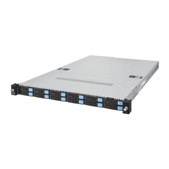
Chapter 1: Overview About the TYAN GC73A-B8046 ® Congratulations on your purchase of the TYAN GC73A-B8046, a highly optimized 1U rack-mountable barebone system. The GC73A-B8046 is designed to support single AMD EPYC™ 8004 Series Processor and up to 1,536GB RDIMM DDR5 4800/3600 memory, providing a rich feature set and incredible performance. -
Page 24: Features
Features GC73A-B8046 (B8046G73AE12HR) Form Factor 1U Rackmount Chassis Model GC73A Dimension (D x W x H) 28.74" x 17.26" x 1.72" (730 x 438.5 x 43.6mm) System Motherboard Name S8046GM Gross Weight 26.75 kg (58.97 lbs) Net weight 13.75 kg (30.31 lbs) Board Dimension Prop. - Page 25 Others (1) DC-SCM slot Physical Dimension FH/FL (Full-height / Full-length): 4.4" x 12.3" Abbreviation (111.2 x 312mm) / FH/HL (Full-height / Half-length): 4.4" x 6.6" (111.2 x 167.7mm) Realtek RTL8211F Connector (M.2) (2) 22110/2280 (by PCIe Gen.3 interface) Storage NVMe Connector (U.2) (6) SFF-TA-1016 (MCIO 8x) for (12) front NVMe (1) USB2.0 port (@ rear) / (1) USB3.2 Gen.1 port...
- Page 26 Contains Manual (1) Quick Installation Guide RoHS RoHS 6/6 Compliant NOTE: 1. The specifications are subject to change without prior notice. 2. Please visit our Web site for the latest specifications. http://www.tyan.com...
-
Page 27: Standard Parts List
Standard Parts List This section describes GC73A-B8046 package contents and accessories. Open the box carefully and ensure that all components are present and undamaged. The product should arrive packaged as illustrated below. 1.3.1 Box Contents and Accessories If any items are missing or appear damaged, contact your retailer or browse to TYAN’s website for service: http://www.tyan.com GC73A-B8046 Box Content:... -
Page 28: About The Product
About the Product The following views show you the product. 1.4.1 System Front View Description Description USB3.2 Gen1 Port (M1725G68-USB Power Button with green & red LED pre-installed) Drive Trays ID Button with blue LED http://www.tyan.com... - Page 29 Front Panel Button and LED (M1724G68-FPB pre-installed) Item Color Behavior System Power On / Green Solid On Power Button Green/Red System Power Off / All Off System Warning / Red Solid On ID Button Blue ID Located / Blue Solid On HDD LED Definitions Drive Status Activity LED (Green)
-
Page 30: System Rear View
1.4.2 System Rear View Description PSU0 PSU1 PCIe Gen5 x16 slot via M8046G73-L16-1F riser card support FH/HL Double wide GPU card supported by CEM cable Release Latch IPMI Port UART Port USB2.0 Port Mini Display Port ID Button with LED Power Button with LED Rear Panel LED Indication Color... -
Page 31: Psu And Lan Led Indications
1.4.3 PSU and LAN LED Indications PSU 1+1 Redundancy Warning LED Indications PSU LED Indications Power Supply Condition LED State Output ON and OK Green No AC power to all power supplies PSU standby state AC present / Only 12VSB 1Hz Blink Green Power supply is cold standby state or always standby state as defined in the Cold... - Page 32 1Gbps LAN Port Indications 1Gbps LAN Link/Activity LED Scheme Left LED Right LED (Link/Activity) (Speed) LED Color: Green LED Color: Amber No Link Link Green Solid On 10 Mbps Active Green Blinking Link Green Solid On Green Solid On 100 Mbps Active Green Blinking Green Solid On...
-
Page 33: System Top View
1.4.4 System Top View Description Description M1725G68-USB PSU0 (pre-installed) M1724G68-FPB PSU1 (pre-installed) M8046G73-L16-1F Riser Card 2.5” SSD/HDD Trays (pre-installed) M1299G68A-BPE-12 HDD Backplane Board TM-DCSCM-8046 (pre-installed) (pre-installed) CEM Cable (2) 4028 + (8) 4056 fans (2) MCIO connector to PCIe x8 Gen5 Cable http://www.tyan.com... -
Page 34: Chassis Dimensions
1.4.5 Chassis Dimensions http://www.tyan.com... -
Page 35: Chapter 2: Setting Up
Chapter 2: Setting Up 2.0.1 Before you Begin This chapter explains how to install the CPUs, CPU heatsinks, memory modules, and hard drives. Instructions on inserting add on cards are also given. 2.0.2 Work Area Make sure you have a stable, clean working environment. Dust and dirt can get into components and cause malfunctions. -
Page 36: Precautions
2.0.4 Precautions Components and electronic circuit boards can be damaged by discharges of static electricity. Working on a system that is connected to a power supply can be extremely dangerous. Follow the guidelines below to avoid damage to GC73A-B8046 or injury to yourself. ... -
Page 37: Installing Motherboard Components
Installing Motherboard Components This section describes how to install components on to the motherboard, including CPUs, memory modules and add-on cards. 2.1.1 Removing the Chassis Cover Follow these instructions to remove the GC73A-B8046 chassis cover. 1. Press the latches simultaneously and push the rear cover backwards to lift it 2. - Page 38 3. Remove two screws on the front chassis cover. Push the front cover forwards to lift it up. http://www.tyan.com...
-
Page 39: Replacing The Chassis Cover
2.1.2 Replacing the Chassis Cover Follow these instructions to replace the GC73A-B8046 chassis cover. 1. Place the front top cover on the chassis and slide it backwards. Secure the front top cover with two screws. 2. Replace the GPU and DIMM air duct. http://www.tyan.com... - Page 40 3. Place the rear top cover on the chassis. Press the latches simultaneously and slide it forwards. http://www.tyan.com...
-
Page 41: Installing The Cpu, Heatsink And Air Ducts
2.1.3 Installing the CPU, Heatsink and Air Ducts Follow the steps below on installing CPU and CPU heat sink. The GC73A-B8046 supports single AMD EPYC 8004 series CPU. The following installation is based on an AMD SP6 socket. 1. Use a T20 Torx screwdriver to loosen the screws securing the force frame. Note: The force frame will automatically eject after the captive screws are being released. - Page 42 3. Remove the external cap from the rail frame. 4. Remove the protective cap. 5. Align and install the carrier frame with package into the slot on the rail frame. http://www.tyan.com...
- Page 43 NOTE: During installation, observe the following: 1. Make sure to push the carrier frame with package towards the end of the rail frame until it clicks into place. 2. Do not drop the carrier frame or touch the package pad to avoid component damage.
-
Page 44: Installing The Memory
2.1.4 Installing the Memory Follow these instructions to install the memory modules onto the motherboard. Unlock the clips. Insert the memory module. Lock the clips. http://www.tyan.com... - Page 45 Memory Population table DIMM SLOT Silk screen DIMM SLOT Silk screen P0_DIMM_A0 P0_CHA_DIM0 P0_DIMM_E0 P0_CHE_DIM0 P0_DIMM_A1 P0_CHA_DIM1 P0_DIMM_E1 P0_CHE_DIM1 P0_DIMM_B0 P0_CHB_DIM0 P0_DIMM_F0 P0_CHF_DIM0 P0_DIMM_B1 P0_CHB_DIM1 P0_DIMM_F1 P0_CHF_DIM1 P0_DIMM_D0 P0_CHD_DIM0 P0_DIMM_H0 P0_CHH_DIM0 P0_DIMM_D1 P0_CHF_DIM1 P0_DIMM_H1 P0_CHH_DIM1 http://www.tyan.com...
- Page 46 DIMM Population Based on Number of Channels Quantity of memory installed CPU Installed 1 Channel 2 Channel 4 Channel 6 Channel Populated Populated Populated Populated 1DPC 2DPC 1DPC 2DPC 1DPC 2DPC 1DPC 2DPC P0_CHA_DIM0 P0_CHA_DIM1 P0_CHB_DIM0 P0_CHB_DIM1 P0_CHD_DIM0 P0_CHD_DIM1 P0_CHE_DIM0 P0_CHE_DIM1 P0_CHF_DIM0 P0_CHF_DIM1...
-
Page 47: Installing The Expansion Card
2.1.5 Installing the Expansion Card Follow these instructions to install the expansion card. 1. Loosen two screws to take out the riser card bracket. 2. Unscrew to remove the dummy bracket. http://www.tyan.com... - Page 48 3. Insert the expansion card into the riser card bracket and secure with a screw. 4. Replace and screw the Riser Card Bracket to the chassis. http://www.tyan.com...
-
Page 49: Installing The 2.5" Hard Drive
2.1.6 Installing the 2.5” Hard Drive Follow these instructions to install the 2.5” hard drives. 1. Press the locking tab to pull the lever open. 2. Slide the drive tray out. 3. Press the locking tab to pull the tray side rail open. http://www.tyan.com... - Page 50 4. Align the hard drive with the guide pins and install the hard drive into the drive tray. Close the tray side rail. http://www.tyan.com...
- Page 51 5. Insert the drive tray into the chassis and close the lever. http://www.tyan.com...
-
Page 52: Installing The M.2 Card
2.1.7 Installing the M.2 Card Follow these instructions to install the M.2 Card. 1. Measure the M.2 card length and insert the M.2 latch into the appropriate hole. 2. Turn the M.2 latch 90 degrees to the left. 3. Insert the M.2 card into the slot. Close the latch to lock the M.2 card. http://www.tyan.com... - Page 53 http://www.tyan.com...
-
Page 54: Installing The Gpu Card
2.1.8 Installing the GPU Card Follow these instructions to install the GPU Card. 1. Use a screwdriver to loosen two screws. 2. Loosen four screws on the rear. 3. Flip the GPU bracket over. Unscrew to remove the dummy brackets. http://www.tyan.com... - Page 55 4. Insert the GPU card into the slot. 5. Screw the GPU card to the GPU bracket. http://www.tyan.com...
- Page 56 6. Connect the GPU power cable. 7. Flip the GPU bracket over to screw the GPU bracket to the chassis. http://www.tyan.com...
-
Page 57: Installing The Ocp Card
2.1.9 Installing the DC-SCM Card Follow these instructions to install the DC-SCM Card. Here a TM-DCSCM-8046 card is used for demonstration. 1. Use a screwdriver to loosen the screw. 2. Pull the DC-SCM bracket away from the chassis. 3. Flip the DC-SCM bracket over. Use a screwdriver to loosen two screws and replace with a new card. - Page 58 4. Insert the new DC-SCM bracket into the chassis. http://www.tyan.com...
-
Page 59: Rack Mounting
Rack Mounting After installing the necessary components, GC73A-B8046 can be mounted in a rack using the supplied rack mounting kit. Rack mounting kit Rails x 2 Screw Sacks x 2 2.2.1 Installing the Server in a Rack Follow these instructions to mount the GC73A-B8046 into an industry standard 19”... -
Page 60: Installing Slide Rails To The Rack
2.2.2 Installing Slide Rails to the Rack Take out the tool-less rail set from the accessory kit. Push the white tab in the direction as the arrow shows to draw out the inner rail. Attach the inner rails to both sides of the chassis. Push the inner rails backwards to lock in place. - Page 61 NOTE: Use a screwdriver to slightly push the latch open and then push the inner rail forwards to unlock. Attach the outer rail to the rack. Pull the latch open and align the square stud with the square hole on the rack rail. Please note that the square stud must be fully attached inside the square hole and then close the latch to lock.
- Page 62 Front http://www.tyan.com...
-
Page 63: Rack Mounting The Server
2.2.3 Rack mounting the Server 1. Install the chassis. Draw out the rails half way and then slide the chassis into the rails. Must be done with at least 2 people. Properly place the chassis directly on the rack and install. 2. - Page 64 3. Fasten the chassis ear to the front surface of chassis. http://www.tyan.com...
-
Page 65: Removing The Server From Rack
2.2.4 Removing the Server from Rack Release the chassis ears by loosening the screws. Pull out the chassis half way to the lock position. Push the white locking tabs forwards to slide the chassis all out from the rack. Caution: Remove the server from the rack carefully. -
Page 66: Chapter 3: Replacing Pre-Installed Components
Chapter 3: Replacing Pre-Installed Components Introduction This chapter explains how to replace the pre-installed components, including the S8046 Motherboard, M1724G68-FPB Front Panel Board, M1725G68-USB Front USB Board, M8046G73-L16-1F Riser Card, M1299GC68A-BPE-12 HDD Backplane Board, System Fan and Power Supply etc. Disassembly Flowchart The following flowchart outlines the disassembly procedure. -
Page 67: Removing The Cover
Removing the Cover Follow Chapter 2.1.2 to remove the cover of GC73A-B8046. Replacing the Power Supply To replace the power supply follow these instructions. 1. Press the latch as shown to pull out the power supply module. 2. Replace a new single power and reinsert it into the power cage following the above steps in reverse. -
Page 68: Replacing The Front Panel Board
Replacing the Front Panel Board Follow these instructions to replace the M1724G68-FPB Front Panel Board. 1. Loosen 3 screws to release the front panel bezel from the chassis. 2. Loosen 2 screws to remove the front panel cage and bracket. 3. -
Page 69: Front Panel Board Features
3.5.1 Front Panel Board Features Front View Rear View M1724G68-FPB Front Panel Board Form Factor 33.5*21*1.6 mm (1) Signal Connector (J1) Integrated I/O (1) PWR Button (1) ID Button http://www.tyan.com... -
Page 70: Replacing The Usb Board
Replacing the USB Board Follow these instructions to replace the M1725G68-USB USB Board. 1. Loosen 3 screws to release the front USB bezel from the chassis. 2. Loosen 2 screws to remove the USB cage and bracket. 3. Disconnect the cable and unscrew the USB Board. 4. -
Page 71: Usb Board Features
3.6.1 USB Board Features Front View Rear View M1725G68-USB Front Panel Board Form Factor 31.9*19.4*1.6 mm (1) Signal Connector (J2) Integrated I/O (1) USB3.0 Connector http://www.tyan.com... -
Page 72: Replacing The Hdd Backplane Board
Replacing the HDD Backplane Board Follow these instructions to replace the M1299G68A-BPE-12 HDD Backplane Boards. 1. First pull the HDD trays out. Disconnect all cables connected to the M1299G68A-BPE-12 HDD Backplane Board. 2. Use a screwdriver to unscrew the M1299G68A-BPE-12 HDD Backplane Board. -
Page 73: Hdd Bp Board Features
3.7.1 HDD BP Board Features Front View Rear View M1299G68A-BPE-12 HDD Backplane Board Form Factor 435*38.3*2.6 mm PCI-E Gen4 12-pot NVMe U.2 BP Board (12) Hot-swap 2.5” NVMe U.2 SSD (2) ATX 2x4-pin Power Connector Integrated I/O (2) 5V connector for DOM (6) Slim-SAS connector (8) Fan connector (1) 2x15-pin Fan Control Connector (J31) -
Page 74: Replacing The Riser Card
Replacing the Riser Card Follow these instructions to replace the M8046G73-L16-1F Riser Card. 1. Lift up the Riser Card Bracket from the chassis. Unscrew to replace with a new riser card M8046G73-L16-1F. 2. Follow the steps described earlier in reverse order to reinstall the riser card bracket into the chassis. -
Page 75: Riser Card Features
3.8.1 Riser card Features M8046G73-L16-1F Riser Card Form Factor 158.00mm*29.34mm, 12 Layers PCI-E x16 Gen5 adapter card Specification (1) PCI-E x16 Gen5 slot support (1) PCI-E x16 Add-on card 3.8.2 Connector Pin Definitions MINI-PCI-E (GF) Signal Name Signal Name VDD_33_RUN VDD_33_RUN VDD_33_DUAL VDD_33_RUN... - Page 76 PETn0 PERp0 PRSNT# PERn0 PETp1 RSVD PETn1 PERp1 PETp2 PERn1 PETn2 PERp2 PETp3 PERn2 PETn3 PERp3 PRSNT# PERn3 PETp4 RSVD PETn4 PERp4 PETp5 PERn4 PETn5 PERp5 PETp6 PERn5 PETn6 PERp6 PETp7 PERn6 PETn7 PERp7 PRSNT# PERn7 http://www.tyan.com...
- Page 77 PETp8 RSVD PETn8 PERp8 PETp9 PERn8 PETn9 PERp9 PETp10 PERn9 PETn10 PERp10 PETp11 PERn10 PETn11 PERp11 PETp12 PERn11 PETn12 PERp12 PETp13 S100 PERn12 PETn13 S101 S102 S103 S104 PERp13 PETp14 S105 S106 PERn13 PETn14 S107 S108 S109 S110 PERp14 PETp15 S111 S112 PERn14...
- Page 78 PCI-E slot X16 (PCIE1) Signal Name Signal Name PCIE_SLOTX16_R_SMB_SCK J_TCK_PESLOT1 PCIE_SLOTX16_R_SMB_SDA J_TDI_PESLOT1 J_TDO_PESLOT1 VDD_33_RUN J_TMS_PESLOT1 VDD_33_DUAL VDD_33_RUN J_TRST_N_PCIEX16 VDD_33_RUN P_CONN_PCIE_WAKE_L P_PCIE_RESET0_L NC_X16_SLOT_RSVD_B12 CLK_100M_PCIE_SLOT1_1_DP PETp0 CLK_100M_PCIE_SLOT1_1_DN PETn0 PERp0 PESLOT1_PRSNT_N PERn0 PETp1 PESLOT1_PRSNT_N PETn1 PERp1 PERn1 PETp2 http://www.tyan.com...
- Page 79 PETn2 PERp2 PERn2 PETp3 PETn3 PERp3 NC_PESLOT1_RSVD_B30 PERn3 PESLOT1_PRSNT_N NC_X16_SLOT_RSVD_A32 PETp4 NC_X16_SLOT_RSVD_A33 PETn4 PERp4 PERn4 PETp5 PETn5 PERp5 PERn5 PETp6 PETn6 PERp6 PERn6 PETp7 PETn7 PERp7 PESLOT1_PRSNT_N PERn7 PETp8 NC_X16_SLOT_RSVD_A50 http://www.tyan.com...
- Page 80 PETn8 PERp8 PERn8 PETp9 PETn9 PERp9 PERn9 PETp10 PETn10 PERp10 PERn10 PETp11 PETn11 PERp11 PERn11 PETp12 PETn12 PERp12 PERn12 PETp13 PETn13 PERp13 PERn13 PETp14 PETn14 PERp14 PERn14 http://www.tyan.com...
- Page 81 PETp15 PETn15 PERp15 PESLOT1_PRSNT_N PERn15 PESLOT1_RSVD_B82 http://www.tyan.com...
-
Page 82: Replacing The Fan
Replacing the Fan Follow these instructions to replace the fan module. 1. Disconnect the fan PWR cable. 2. Lift up the fan module from the chassis. 3. Release the rubber screws and push pins from the fan module. Replace with a new fan and then insert the rubber screws and push pins. - Page 83 4. Place the new fan module into the chassis and reconnect the fan cable. Remember to tie cables after fan replacement. http://www.tyan.com...
-
Page 84: Replacing The Motherboard
3.10 Replacing the Motherboard After removing all of the aforementioned components, follow these instructions to remove the motherboard from the chassis. 1. Disconnect all cables connected to the mainboard. 2. Remove eight screws securing the motherboard to the chassis. Carefully remove the motherboard from the chassis for replacement. -
Page 85: Chapter 4: Mainboard Information
Unplug the power from your computer power supply and then touch a safely grounded object to release static charge (i.e. power supply case). For the safest conditions, MITAC recommends wearing a static safety wrist strap. (2) Hold the motherboard by its edges and do not touch the bottom of the board, or flex the board in any way. -
Page 86: Board Image
Board Image S8046GMRE This picture is representative of the latest board revision available at the time of publishing. The board you receive may not look exactly like the above picture. http://www.tyan.com... -
Page 87: Block Diagram
Block Diagram S8046GM Block Diagram http://www.tyan.com... -
Page 88: Mainboard Mechanical Drawing
Mainboard Mechanical Drawing http://www.tyan.com... -
Page 89: Board Parts, Jumpers And Connectors
Board Parts, Jumpers and Connectors This diagram is representative of the latest board revision available at the time of publishing. The board you receive may not look exactly like the above diagram. But for the DIMM number please refer to the above placement for memory installation. For the latest board revision, please visit our web site at http://www.tyan.com. - Page 90 Jumpers & Connectors Connectors 1. Power Supply Connector (PSU1) 14. MCIO Connector (CN3) 2. Power Supply Connector (PSU) 15. MCIO Connector (CN9) 3. MCIO Connector (CN6) 16. MCIO Connector (CN10) 4. MCIO Connector (CN5) 17. MCIO Connector (CN7) 5. DC-SCM Connector (OCP3_1) 18.
- Page 91 Jumper Legend OPEN - Jumper OFF Without jumper cover CLOSED - Jumper ON With jumper cover http://www.tyan.com...
- Page 92 CPU0_FAN: 4 Pin CPU Fan Connector Signal Name TACH J7/J9/J14/J15/J16/J18/J22/J23 (SYSFAN1~8): 8 Pin SYSTEN FAN Connector Signal Name Signal Name VDD_12_RUN FAN_TACH1 FAN_PWM VDD_12_RUN FAN_TACH0 FAN_PWM J1: HDT JTAG Header Signal Name Signal Name VDD_18_DUAL HDT_TCK HDT_TMS HDT_TDI HDT_TDO HDT_TRST_L HDT _PWROK HDT_XTRIG6_L HDT_RESET_L...
- Page 93 FPIO_2 (SSL_FP): Front Panel Header Signal Name Signal Name FP_PW_LED_PW VCC_FPB FP_ID_LED_PW FP_PW_LED_GND FP_ID_LED_N HDD_LED_PW BMC_HW_FAULT_N HDD_ACT_LED_N BMC_SYS_FAULT_N FP_PWR_BTN_N FP_RST_BTN_JP_N FP_SMB_DAT FP_SMB_CLK FP_IDLED_BTN_N FP_INTRUSION_N SYS_AIR_INLET FP_NMI_BTN_N IPMB1: 4 Pin IPMB Connector Signal Name IPMB_DAT IPMB_CLK VCC33 PWR_BTN1: Power Button Signal Signal FP_PWR_BTN_N http://www.tyan.com...
- Page 94 RST_BTN1: Reset Button Signal Signal FP_RST_BTN_N USB3_FPIO1 (USB3.0): USB3.0 Header Signal Name Signal Name USB3_VCC_FPB USB3_N1_RX_FPB USB3_VCC_FPB USB3_P1_RX_FPB USB3_N0_RX_FPB USB3_P0_RX_FPB USB3_N1_TX_FPB USB3_P1_TX_FPB USB3_N0_TX_FPB USB3_P0_TX_FPB USB2_N1_FPB_R USB2_P1_FPB_R USB2_N0_FPB_R USB2_P0_FPB_R TYPE A_USB: Vertical Type-A USB3.0 Connector Signal Name Signal Name VCC5 USB3_P3_TX_TYPEA USB2_N_TYPE_A_R USB3_N3_TX_TYPEA USB2_P_TYPE_A_R...
- Page 95 J66: Chassis Intruder Header Pin1 Pin2 CHASSIS_INTR_L For Open Chassis Debug A Jumper Must Be Populated 1-2 : Chassis Cover Is Closed (Default) Empty Chassis Cover Is Closed Removed J25: MINI-PCI-E slot X16 (FOR M8046G73-R16-1F) Signal Name Signal Name VDD_33_RUN VDD_33_RUN VDD_33_DUAL VDD_33_RUN...
- Page 96 PETn1 PERp1 PETp2 PERn1 PETn2 PERp2 PETp3 PERn2 PETn3 PERp3 PRSNT# PERn3 PETp4 RSVD PETn4 PERp4 PETp5 PERn4 PETn5 PERp5 PETp6 PERn5 PETn6 PERp6 PETp7 PERn6 PETn7 PERp7 PRSNT# PERn7 PETp8 RSVD PETn8 PERp8 PETp9 PERn8 http://www.tyan.com...
- Page 97 PETn9 PERp9 PETp10 PERn9 PETn10 PERp10 PETp11 PERn10 PETn11 PERp11 PETp12 PERn11 PETn12 PERp12 PETp13 S100 PERn12 PETn13 S101 S102 S103 S104 PERp13 PETp14 S105 S106 PERn13 S107 S108 PETn14 S109 S110 PERp14 S111 S112 PETp15 PERn14 PETn15 S113 S114 S115 S116 PERp15...
- Page 98 OCP3_1 (DC_SCM): DC_SCM Connector Signal Name Signal Name OB1 OA1 P0_USB_SS_TX_L<1> OB2 OA2 P0_USB_SS_RX_L<1> P0_USB_SS_TX_H<1> OB3 OA3 P0_USB_SS_RX_H<1> OB4 OA4 OB5 OA5 OB6 OA6 OB7 OA7 OB8 OA8 OB9 OA9 USB2_HUB_DN1 USB2_HUB_DP1 P0_VDD_VDDIO_RUN PECI_SCM P0_ESPI_SCM_CLK P12VSB P0_ESPI_SCM_CS_L_R1 P12VSB P0_LPC_ESPI_RST_BMC_N P12VSB P0_ESPI_SCM_DATA0 P12VSB P0_ESPI_SCM_DATA1...
- Page 99 P0_ESPI0_SCM_ALERT_L JTAG_BMC_TCK JTAG_BMC_TDO B10 A10 JTAG_XDP_BMC_TDI B11 A11 JTAG_XDP_BMC_TMS B12 A12 P0_SPI_R_CLK<0> SCM_HDT_TRST_L P0_SPI_R_CS_L<0> B13 A13 FM_HPM_STBY_RST_N B14 A14 P0_SPI_R_0_DATA<0> FM_HPM_STBY_EN P0_SPI_R_0_DATA<1> B15 A15 BMC_SMB_SCL5 P0_SPI_R_0_DATA<2> B16 A16 BMC_SMB_SDA5 P0_SPI_R_0_DATA<3> B17 A17 BMC_SMB_SCL6 P0_SPI_R_CS_L<1> B18 A18 BMC_SMB_SDA6 B19 A19 LVDS_TX_DN B20 A20 LVDS_RX_DN LVDS_TX_DP...
- Page 100 P0_USB_HS_L<1> B36 A36 CLK_100M_BMC_DN P0_USB_HS_H<1> B37 A37 CLK_100M_BMC_DP B38 A38 BMC_1V8_SMB_SCL14 B39 A39 BMC_I3C_DIMM0_ABD_SCL B40 A40 BMC_1V8_SMB_SDA14 BMC_I3C_DIMM0_ABD_SDA B41 A41 BMC_I3C_DIMM0_EFH_SCL B42 A42 BMC_I3C_DIMM0_EFH_SDA NCSI_BMC_MAC1_CLKIN50M B43 A43 BMC_SMB_SCL13 NCSI_BMC_MAC1_CRSDV B44 A44 BMC_SMB_SDA13 NCSI_BMC_MAC1_TX_EN B45 A45 BMC_SMB_SCL8 NCSI_BMC_MAC1_TXD0 B46 A46 BMC_SMB_SDA8 NCSI_BMC_MAC1_TXD1 B47 A47 BMC_SMB_SCL12...
- Page 101 DCSCM_B63 B63 A63 UART0_HPM_SCM_DATA B64 A64 B65 A65 B66 A66 B67 A67 USB2_HUB_DN2 B68 A68 CLK_100M_BMC _DN B69 A69 USB2_HUB_DP2 CLK_100M_BMC _DP B70 A70 http://www.tyan.com...
- Page 102 CN1/CN11/CN5/CN6/CN3/CN4/CN7/CN8/CN9/CN10: MCIO Connector (CN1, CN11 FOR SATA & NVME) (CN5, CN6 FOR CEM cable) (CN3, CN4, CN7, CN8, CN9, CN10 FOR NVME) Signal Name Signal Name PCIE_NVME0_RX_L0 PCIE_NVME0_TX_L0 PCIE_NVME0_RX_H0 PCIE_NVME0_TX_H0 PCIE_NVME0_RX_L1 PCIE_NVME0_TX_L1 PCIE_NVME0_RX_H1 PCIE_NVME0_TX_H1 SLIMSAS_BP_TYPE0 NVME0_SMB_SCL PCIE_WAKE_L NVME0_SMB_SDA CLK_100M_NVME0_DP NVME0_PERST_L CLK_100M_NVME0_DN NVME0_PRSNT_L PCIE_NVME0_RX_L2...
- Page 103 PCIE_NVME1_RX_L5 PCIE_NVME1_TX_L5 PCIE_NVME1_RX_H5 PCIE_NVME1_TX_H5 SLIMSAS_BP_TYPE1 NVME1_SMB_SCL PCIE_WAKE_L NVME1_SMB_SDA CLK_100M_NVME1_DP NVME1_PERST_L CLK_100M_NVME1_DN NVME1_PRSNT_L PCIE_NVME1_RX_L6 PCIE_NVME1_TX_L6 PCIE_NVME1_RX_H6 PCIE_NVME1_TX_H6 PCIE_NVME1_RX_L7 PCIE_NVME1_TX_L7 PCIE_NVME1_RX_H7 PCIE_NVME1_TX_H7 http://www.tyan.com...
- Page 104 M2_CN1, M2_CN2 (M.2#1, M.2#2): M.2 Connector Signal Name Signal Name VDD_33_RUN VDD_33_RUN I/O/LED VDD_33_RUN VDD_33_RUN VDD_33_RUN VDD_33_RUN PERN1 PERP1 PETN1 PETP1 M2_SMB_CLK2 PERN0 M2_SMB_DAT2 PERP0 http://www.tyan.com...
- Page 105 PETN0 PETP0 PCIE_PERST_N REFCLKN PCIE_WAKE_L REFCLKP PCIE_ SATA _SEL VDD_33_RUN VDD_33_RUN VDD_33_RUN J75: CLEAR CMOS Jumper Pin1 Pin2 Pin3 VDD_RTC_JMPR VDD_RTC_L (Default) Pin1-2 closed: Normal Mode Pin2-3 closed: CLEAR CMOS J20: SPI Voltage Select Jumper Signal Signal VDD_33_DUAL VDD_3V3_1V8_SEL VDD_18_DUAL (Default) Pin1-2 closed: SPI P3V3 Pin2-3 closed: SPI P1V8...
- Page 106 J4: DCSCM LTPI Select Jumper Signal Signal DCSCM_LTPI_MUX DCSCM_CPLD_SGPIO (Default) Pin1-2 closed: DCSCM LTPI 2-3 Pin2-3 closed: DCSCM SGPIO J2: Force Power Options Jumper Pin1 Pin2 Pin3 FORCE_PWRON_LVC3 PU_POWER_LVC3 (Default) Pin1-2 closed: Disable Pin2-3 closed: Enable 3PHD_12: CPU VR Power SMB SET Jumper Pin1 Pin2 Pin3...
-
Page 107: Led Definitions
LED Definitions Signal VDD_33_DUAL SCM_SYS_PWROK- SYS_PWROK LED State Description NORMAIL Green SYSTEM POWER OK Signal CPLD heartbeat LED VDD_33_DUAL CPLD_HB_LED_L http://www.tyan.com... - Page 108 State Description CPLD not ready ON Read 1HZ CPLD READY Signal VDD_33_DUAL HDD_ACT_LED_ALL_L SATA & M.2 LED State Description HDD non-activity Blue HDD activity Signal VDD_33_DUAL PSU_PWRGD PSU_PWRGD State Description POWER OFF Green 12V POWER GOOD Signal VDD_33_DUAL P0_PROCHOT_N PROCHOT LED State Description NORMAIL...
-
Page 109: Installing The Processor And Heat Sink
24. Check our website at http://www.tyan.com for latest processor support. NOTE: MITAC TYAN is not liable for damage as a result of operating an unsupported configuration. Processor Installation for AMD SP6 Socket Follow the steps below to install the processors and heat sinks. - Page 110 3. Remove the external cap from the rail frame. NOTE: Keep the cap for future DOA/RMA usage. 4. Align and install the carrier frame with package into the slot on the rail frame. NOTE: During installation, observe the following: make sure to push the carrier frame with package towards the end of the rail frame until it clicks into place.
- Page 111 5. Using your thumb and forefinger, remove the PnP cap by lifting it up vertically. NOTE: Keep the cap for future DOA/RMA usage. 6. Carefully close the rail frame with the installed package. Then push both edges of the rail frame firmly until it locks in place. 7.
- Page 112 Heatsink Installation 1. Align and install the CPU heatsink onto the top of the CPU socket. 2. Use a T20 Torx screwdriver to tighten the heatsink screws. http://www.tyan.com...
-
Page 113: Tips On Installing Motherboard In Chassis
Some chassis include plastic studs instead of metal. Although the plastic studs are usable, MITAC recommends using metal studs with screws that will fasten the motherboard more securely in place. Below is a chart detailing what the most common motherboard studs look like and how they should be installed. - Page 114 http://www.tyan.com...
-
Page 115: Installing The Memory
Installing the Memory Before installing memory, ensure that the memory you have is compatible with the motherboard and processor. Check the TYAN Web site at http://www.tyan.com details of the type of memory recommended for your motherboard. Supports up to 1536GB of RDIMM DDR5 4800MHz (1DPC) / DIMM DDR5 3600MHz (2DPC). - Page 116 S8046 memory population rules and recommended table DIMM Population/Channel DDR5 Frequency MT/s 14L 74mil low-DK PCB DIMM Type DIMM 0 DIMM 1 stackup RDIMM 4800 4000 4800 3600 DIMM SLOT Silk screen DIMM SLOT Silk screen P0_DIMM_A0 P0_CHA_DIM0 P0_DIMM_E0 P0_CHE_DIM0 P0_DIMM_A1 P0_CHA_DIM1 P0_DIMM_E1...
- Page 117 DIMM Population Based on Number of Channels Quantity of memory installed CPU Installed 1 Channel 2 Channel 4 Channel 6 Channel Populated Populated Populated Populated 1DPC 2DPC 1DPC 2DPC 1DPC 2DPC 1DPC 2DPC P0_CHA_DIM0 P0_CHA_DIM1 P0_CHB_DIM0 P0_CHB_DIM1 P0_CHD_DIM0 P0_CHD_DIM1 P0_CHE_DIM0 P0_CHE_DIM1 P0_CHF_DIM0 P0_CHF_DIM1...
- Page 118 Memory Installation Procedure Follow these instructions to install memory modules into the S8046. Unlock the clips as shown in the illustration. Insert the memory module firmly into the socket by gently pressing down until it sits flush with the socket. Lock the clips to secure the memory module into place.
-
Page 119: Attaching Drive Cables
Attaching Drive Cables Attaching Serial ATA Cables S8046 is equipped with ten (10) Serial ATA (SATA) channel. Connections for the drives are very simple. There is no need to set Master/Slave jumpers on SATA drives. If you are in need of SATA/SAS cables or power adapters please contact your place of purchase. -
Page 120: Installing Add-In Cards
4.10 Installing Add-In Cards Before installing add-in cards, it’s helpful to know if they are fully compatible with your motherboard. For this reason, we’ve provided the diagrams below, showing the slots that may appear on your motherboard. Simply find the appropriate slot for your add-in card and insert the card firmly. Do not force any add-in cards into any slots if they do not seat in place. -
Page 121: Connecting External Devices
4.11 Connecting External Devices Connecting external devices to the motherboard is an easy task. The motherboard supports a number of different interfaces through connecting peripherals. See the following diagrams for the details. NOTE: Peripheral devices can be plugged straight into any of these ports but software may be required to complete the installation. -
Page 122: Installing The Power Supply
4.12 Installing the Power Supply There are (8) eight power connectors on your S8046 motherboard. The S8046 supports EPS 12V power supply. NOTE: You must unplug the power supply before plugging the power cables to motherboard connectors. Warning: The mainboard supports up to 350W CPU TDP with the use of 16AWG... - Page 123 J24: MICRO FIT 4-Pin output Power Connector (FOR CEM cable) Signal Signal P12V P3V3_DUAL P3V3 http://www.tyan.com...
-
Page 124: Finishing Up
4.13 Finishing Up Congratulations on making it this far! You have finished setting up the hardware aspect of your computer. Before closing up your chassis, make sure that all cables and wires are connected properly, especially IDE cables and most importantly, jumpers. -
Page 125: Chapter 5: Bios Setup
Chapter 5: BIOS Setup About the BIOS The BIOS is the basic input/output system, the firmware on the motherboard that enables your hardware to interface with your software. The BIOS determines what a computer can do without accessing programs from a disk. The BIOS contains all the code required to control the keyboard, display screen, disk drives, serial communications, and a number of miscellaneous functions. -
Page 126: Getting Help
Chipset section unless you are absolutely sure of what you are doing. The Chipset defaults have been carefully chosen either by MITAC or your system manufacturer for best performance and reliability. Even a seemingly small change to the Chipset setup options may cause the system to become unstable or unusable. -
Page 127: Main Menu
Main Menu In this section, you can alter general features such as the date and time. Note that the options listed below are for options that can directly be changed within the Main Setup screen. System Language Choose the system default language. English / Simplified Chinese / Japanese System Date Set the Date. -
Page 128: Advanced Menu
Advanced Menu This section facilitates configuring advanced BIOS options for your system. NOTE: This is a sample screenshot of the Advanced Menu. The HII network drivers displayed here depend on the card(s) you installed and the functions you enabled. Network Stack Configuration Network Stack Settings. - Page 129 Super IO Configuration System Super IO Chip Parameters. Hardware Health Configuration Hardware health Configuration Parameters. PCI Subsystem Settings PCI, PCI-X and PCI Express Settings. NVMe Configuration NVMe Devices Information. CSM Configuration CSM Configuration: Enable/Disable, Option ROM execution settings, etc. Trusted Computing Trusted Computing Settings.
-
Page 130: Network Stack Configuration
5.3.1 Network Stack Configuration NOTE: The BIOS will automatically read the onboard LAN controller. Network Stack Enable/Disable UEFI Network Stack. Disabled / Enabled NOTE: The following items are available when Network Stack is set to [Enabled]. Ipv4 PXE Support Enable Ipv4 PXE Boot Support. If disabled IPV4 PXE boot option will not be available. - Page 131 Ipv6 HTTP Support Enable Ipv6 HTTP Boot Support. If disabled IPV6 HTTP boot option will not be available. Disabled / Enabled PXE boot wait time Wait time to press ESC key to abort the PXE boot. Media detect count Number of times the presence of media will be checked. Use either +/- or numeric keys to set the value.
-
Page 132: S5 Rtc Wake Settings
5.3.2 S5 RTC Wake Settings Wake system from S5 Enable or disable System wake on alarm event. Select FixedTime, system will wake on the hr::min::sec specified. Select DynamicTime, System will wake on the current time + Increase minute(s). Disabled / Fixed Time / Dynamic Time When Wake system from S5 is set to [Fixed Time] Wake up hour Select 0-23. -
Page 133: Serial Port Console Redirection
5.3.3 Serial Port Console Redirection Console Redirection / Console Redirection EMS Console redirection enable or disable. Disabled / Enabled Legacy Console Redirection Settings Legacy Console redirection settings. Console Redirection Settings The settings specify how the host computer (which the user is using) will exchange data. - Page 134 5.3.3.1 COM1 Console Redirection Settings Terminal Type Emulation: ANSI: Extended ASCII char set. VT100: ASCII char set. VT100+: Extends VT100 to support color, function keys, etc. VT-UTF8: Uses UTF8 encoding to map Unicode chars onto 1 or more bytes. VT100+ / VT100 / VT-UTF8 / ANSI Bits per Second Select serial port transmission speed.
- Page 135 Stop Bits Stop bits indicate the end of a serial data packet. (A start bit indicates the beginning). The standard setting is 1 stop bit. Communication with slow devices may require more than 1 stop bit. 1 / 2 Flow Control Flow Control can prevent data loss from buffer overflow.
- Page 136 5.3.3.2 Legacy Console Redirection Settings Legacy Serial Redirection Port Select a COM port to display redirection of Legacy OS and Legacy OPROM Messages. COM1 Resolution On Legacy OS, the Number of Rows and Columns supported redirection. 80x24 / 80x25 Redirect After POST When BootLoader is selected, then Legacy Console Redirection is disabled before booting to legacy OS, When Always Enable is selected, then Legacy Console Redirection is enabled for legacy OS.
- Page 137 5.3.3.3 Serial Port for Out-Of-Band Management/Windows Emergency Services (EMS) Console Redirection Settings Out-of-Band Mgmt Port Microsoft Windows Emergency Management Services (EMS) allows for remote management of a Windows Server OS through a serial port. COM1 Terminal Type VT-UTF8 is the preferred terminal type for out-of-band management. The next best choice is VT100+ and then VT100.
- Page 138 Flow Control Flow Control can prevent data loss from buffer overflow. When sending data, if the receiving buffers are full, a ‘stop’ signal can be sent to stop the data flow. Once the buffers are empty, a ‘start’ signal can be sent to restart the flow. Hardware flow control uses two wires to send start/stop signal.
-
Page 139: Pcie Device Configuration
5.3.4 PCIe Device Configuration PCIe Slot Bifurcation PCIe Slot Bifurcation. PCIe Slot Speed PCIe Slot Speed. http://www.tyan.com... - Page 140 5.3.4.1 Option ROM Dispatch Policy MINI PCIE Option ROM Enable or Disable Option ROM execution for selected Slot. Enabled / Disabled PCIE RISER Option ROM Enable or Disable Option ROM execution for selected Slot. Enabled / Disabled http://www.tyan.com...
- Page 141 5.3.4.2 PCIe Slot Bifurcation MINI PCIE Bifurcation Selects PCIE port Bifurcation for MINI PCIE slot. X16 / x8x8 / x4x4x4x4 PCIE RISER Bifurcation Selects PCIE port Bifurcation for PCIE RISER slot. X16 / x8x8 / x4x4x4x4 http://www.tyan.com...
- Page 142 5.3.4.3 PCIe Slot Speed MINI PCIE Speed Maximum Link Speed for MINI PCIE slot. Auto / GEN1 (2.5GT/s) / GEN2 (5GT/s) / GEN3 (8GT/s) / GEN4 (16GT/s) / GEN5 (32GT/s) PCIE RISER Speed Maximum Link Speed for PCIE RISER slot. Auto / GEN1 (2.5GT/s) / GEN2 (5GT/s) / GEN3 (8GT/s) / GEN4 (16GT/s) / GEN5 (32GT/s) http://www.tyan.com...
-
Page 143: Usb Configuration
5.3.5 USB Configuration Legacy USB Support Enables USB legacy support. AUTO option disables legacy support if no USB devices are connected. DISABLE option will keep USB devices available only for EFI applications. Disabled / Enabled / Auto XHCI Hand-off This is a workaround for OSes without XHCI hand-off support. The XHCI ownership change should be claimed by XHCI driver. - Page 144 USB transfer time-out The time-out value for Control, Bulk and Interrupt transfers. 1 sec / 5 sec / 10 sec / 20 sec Device reset time-out USB mass storage device Start Unit command time-out. 10 sec / 20 sec / 30 sec / 40 sec Device power-up delay Maximum time the device will take before it properly reports itself to the Host Controller.
-
Page 145: Onboard Device Configuration
5.3.6 Onboard Device Configuration Onboard VGA Enable/Disable ASPEED VGA. Enabled / Disabled Primary Display Select active Video type. Onboard / External NMI Function Enable or Disable NMI function. Enabled / Disabled Chassis Intrusion Detection Enabled: When a chassis open event is detected, the BIOS will display the event. Enabled / Disabled Clock Spread Spectrum Enable/Disable Clock Spread Spectrum. -
Page 146: Super Io Configuration
5.3.7 Super IO Configuration Serial Port 1 Configuration Set Parameters of Serial Port 1 (COMA). http://www.tyan.com... - Page 147 5.3.7.1 Serial Port 1 Configuration Serial Port Enable or disable Serial Port (COM). Enabled / Disabled Device Settings Read only. Change Settings Select an optimal setting for Super IO Device. Auto / IO=3F8h; IRQ=4; / IO=2F8h, IRQ=4; / IO=3E8h, IRQ=4; / IO=2E8h, IRQ=4;...
-
Page 148: Hardware Health Configuration
5.3.8 Hardware Health Configuration Fan Speed Control Fan Speed Control. Automatic / Manual / Full Speed NOTE: Change the Fan Speed Control BIOS setting from [Manual] to [Full Speed] when installing the Nvidia GeForce / Quardro GPU and any VGA card. PWM Minimal Duty Cycle PWM Minimal Duty Cycle (%).This item is available when Fan Speed Control is set to [Manual]. - Page 149 Number of PSU (available when PMBus Support is set to [Enabled]) User can select PSU number for needed. 2 / 1 http://www.tyan.com...
- Page 150 5.3.8.1 Sensor Data Register Monitoring http://www.tyan.com...
- Page 151 NOTE: SDR can not be modified. Read only. http://www.tyan.com...
-
Page 152: Pci Subsystem Settings
5.3.9 PCI Subsystem Settings Above 4G Decoding Enables or Disables 64bit capable Devices to be Decoded in Above 4G Address Space (Only if System Supports 64 bit PCI Decoding). Enabled / Disabled SR-IOV Support If system has SR-IOV capable PCIe Devices, this option Enables or Disables Single Root IO Virtualization Support. - Page 153 5.3.9.1 PCI Express Settings Max Payload Set Maximum Payload of PCI Express Device or allow System BIOS to select the value. Auto / 128 Bytes / 256 Bytes / 512 Bytes / 1024 Bytes / 2048 Bytes / 4096 Bytes http://www.tyan.com...
-
Page 154: Csm Configuration
5.3.10 CSM Configuration CSM support Enable/Disable CSM Support. Enabled / Disabled Option ROM Messages Set display mode for Option ROM. Force BIOS / Keep Current Network Controls the execution of UEFI and Legacy PXE OpROM. UEFI / Legacy Storage Controls the execution of UEFI and Legacy Storage OpROM. UEFI / Legacy Video Controls the execution of UEFI and Legacy Video OpROM... - Page 155 Other PCI devices Determines OpRom execution policy for devices other than network, storage, or video UEFI / Legacy http://www.tyan.com...
-
Page 156: Nvme Configuration
5.3.11 NVMe Configuration This page shows the Device you installed. http://www.tyan.com... -
Page 157: Trusted Computing
5.3.12 Trusted Computing Security Device Support Enables or Disables BIOS support for security device. O.S. will not show Security Device. TCG EFI protocol and INT1A interface will not be available. Enabled / Disabled http://www.tyan.com... -
Page 158: Redfish Host Interface Settings
5.3.13 Redfish Host Interface Settings Redfish Enable/Disable AMI Redfish. Enabled / Disabled BMC Redfish Version / BIOS Redfish Version Read only. IP Address Enter IP address. IP Mask Address Enter IP Mask address. IP Port Enter IP Port. http://www.tyan.com... -
Page 159: T1S Auth Configuration
5.3.14 T1s Auth Configuration Server CA Configuration Press <Enter> to configure Server CA. Client Cert Configuration Press <Enter> to configure Client Cert. http://www.tyan.com... - Page 160 5.3.14.1 Server CA Configuration Enroll Cert Press <Enter> to enroll cert. Delete Cert Press <Enter> to delete cert. http://www.tyan.com...
- Page 161 5.3.14.1.1 Enroll Cert Enroll Cert Using File Enroll Cert Using File. Cert GUID Input digit character in 11111111-2222-3333-4444-1234567890ab format. Commit Changes and Exit Commit Changes and Exit. Discard Changes and Exit Discard Changes and Exit. http://www.tyan.com...
- Page 162 5.3.14.1.2 Delete Cert FE9C6606-8B49-44A3-8B6B-DEA3A0E032 GUID for CERT. Disabled / Enabled http://www.tyan.com...
-
Page 163: Iscsi Configuration
5.3.15 iSCSI Configuration Please follow the instructions to initiate the iSCSI function. Step 1. Select Advanced CSM Configuration Network [UEFI]. Step 2. Select Advanced Network Stack Configuration Network Stack [Enabled] Step 3. Save changes and reboot. Host iSCSI Configuration Host iSCSI Configuration http://www.tyan.com... - Page 164 5.3.15.1 Host iSCSI Configuration iSCSI Initiator Name The worldwide unique name of iSCSI Initiator. Only IQN format is accepted. Enter [iqn.xxx]. xxx ranges from 4 to 223. For example: Enter [iqn.45] Add an Attempt Add an Attempt. Delete Attempts Delete one or more attempts. Change Attempt Order Change the order of Attempts using +/- keys.
- Page 165 5.3.15.1.1 Add an Attempt The screen shows the network protocols installed. If no network protocols are installed, the screen displays the message “Necessary network protocols are not available to retrieve….” http://www.tyan.com...
- Page 166 5.3.15.1.2 Delete Attempts Commit Changes and Exit Commit Changes and Exit. Discard Changes and Exit Discard Changes and Exit. http://www.tyan.com...
- Page 167 5.3.15.1.3 Change Attempt Order Commit Changes and Exit Commit Changes and Exit. Discard Changes and Exit Discard Changes and Exit. http://www.tyan.com...
-
Page 168: Mac:xxxxxxxxxxxx - Ipv4 Network Configuration
5.3.16 MAC:xxxxxxxxxxxx - IPv4 Network Configuration Configured Indicate whether network address configured successfully or not. Disabled / Enabled Save Changes and Exit Save Changes and Exit. http://www.tyan.com... -
Page 169: Mac:xxxxxxxxxxxx - Ipv6 Network Configuration
5.3.17 MAC:xxxxxxxxxxxx - IPv6 Network Configuration Enter Configuration Menu Press ENTER to enter configuration menu for IPv6 configuration. http://www.tyan.com... - Page 170 5.3.17.1 Enter Configuration Menu Interface ID The 64 bit alternative interface ID for the device. The string is colon separated, e.g. ff:dd:88:66:cc:1:2:3 xx:xx:x:xx:xx:xx:xx:xx DAD Transmit Count The number of consecutive Neighbor Solicitation messages sent while performing Duplicate Address Detection on a tentative address. A value of zero indicates that Duplicate Address Detection is not performed.
-
Page 171: Vlan Configuration (Mac:xxxxxxxxxxxx)
5.3.18 VLAN Configuration (MAC:xxxxxxxxxxxx) Enter Configuration Menu Press ENTER to enter configuration menu for VLAN configuration. http://www.tyan.com... - Page 172 5.3.18.1 Enter Configuration Menu VLAN ID VLAN ID of new VLAN or existing VLAN, valid value is 0~4094. Priority 802.1Q Priority, valid value is 0~7. Add VLAN Create a new VLAN or update existing VLAN. Remove VLAN Remove selected VLANs. http://www.tyan.com...
-
Page 173: Cpu
CPU Configuration CPU Configuration Parameters. http://www.tyan.com... -
Page 174: Cpu Configuration
5.4.1 CPU Configuration SVM Mode Enable/disable CPU Virtualization. Disabled / Enabled SMEE Control secure memory encryption enable. Disabled / Enabled CPU0 Information View Information related CPU 0. http://www.tyan.com... - Page 175 5.4.1.1 CPU 0 Information Read only. http://www.tyan.com...
-
Page 176: Chipset
Chipset PCIe Compliance Mode PCIe Link Compliance Mode. Disabled / Enabled North Bridge North Bridge Parameters. AMD CBS AMD CBS Setup Page. AMD PBS AMD PBS Setup Page. http://www.tyan.com... -
Page 177: North Bridge
5.5.1 North Bridge CPU 0 Information View Memory Information related to CPU0. http://www.tyan.com... - Page 178 5.5.1.1 CPU 0 Information Read only. http://www.tyan.com...
-
Page 179: Amd Cbs
5.5.2 AMD CBS CPU Common Options CPU Common Options. DF Common Options DF Common Options. UMC Common Options UMC Common Options. NBIO Common Options NBIO Common Options. FCH Common Options FCH Common Options. SOC Miscellaneous Control SOC Miscellaneous Control. http://www.tyan.com... - Page 180 5.5.2.1 CPU Common Options CCD/Core/Thread Enablement CCD/Core/Thread Enablement. Prefetcher settings Prefetcher settings. Platform First Error Handling Enable/Disable PFEH, cloak individual banks, and mask deferred error interrupts from each bank. Enabled / Disabled / Auto Core Performance Boost Disable CPB. Disabled / Auto Global C-state Control Controls IO based C-state generation and DF C-states.
- Page 181 SEV-ES ASID Space Limit SEV-ES and SNP guests must use ASIDs in the range 1 through (this value -1). SEV guests must use ASIDs in the range of this value through 1006. To have all ASIDs support SEV-ES or SNP guests, set this value to 1007. The default is 1: all SEV guests and no SEV-ES or SNP guests.
- Page 182 5.5.2.1.1 CCD/Core/Thread Enablement CCD Control Sets the number of CCDs to be used. Once this option has been used to remove any CCDs, a POWER CYCLE is required in order for future selections to take effect. Auto / 2 CCDs / 4 CCDs / 6 CCDs Core Control Sets the number of cores to be used.
- Page 183 5.5.2.1.2 Prefetcher settings L1 Stream HW Prefetcher Option to Enable/Disable L1 Stream HW Prefetcher. Disabled / Enabled / Auto L2 Stream HW Prefetcher Option to Enable/Disable L2 Stream HW Prefetcher. Disabled / Enabled / Auto http://www.tyan.com...
- Page 184 5.5.2.2 DF Common Options Memory Addressing Memory Addressing. ACPI ACPI. http://www.tyan.com...
- Page 185 5.5.2.2.1 Memory Addressing NUMA nodes per socket Specifies the number of desired NUMA nodes per socket. Zero will attempt to interleave the two sockets together. NPS1 / NPS2 / NPS4 Memory interleaving Allows for disabling memory interleaving. Note that NUMA nodes per socket will be honored regardless of this setting.
- Page 186 5.5.2.2.2 ACPI ACPI SRAT L3 Cache As NUMA Domain Enabled: Each CCX in the system will be declared as a separate NUMA domain. Disabled: Memory Addressing \ NUMA nodes per socket will be declared. Disabled / Enabled / Auto http://www.tyan.com...
- Page 187 5.5.2.3 UMC Common Options DDR Addressing Options DDR Addressing Options. DDR Timing Configuration DDR Timing Configuration. DDR RAS DDR RAS. DDR Security DDR Security. http://www.tyan.com...
- Page 188 5.5.2.3.1 DDR Addressing Options Chipselect Interleaving Interleave DRAM accesses across ranks within a memory channel if the configuration supports it. ‘Enable’ will override certain optimization policies, but cannot force interleaving on configurations that do not support it. Disabled / Auto BankSwapMode BankSwapMode value: 0=Disabled;...
- Page 189 5.5.2.3.2 DDR Timing Configuration Active Memory Timing Settings Active Memory Timing Settings. Auto / Enabled Memory Target Speed Specifies the memory target speed in MT/s. Auto / DDR3200 / DDR3600 / DDR4000 / DDR4400 / DDR4800 http://www.tyan.com...
- Page 190 5.5.2.3.3 DDR RAS Data Poisoning Enable poison data creation on uncorrectable DDR DRAM ECC errors and poison propagation to CPU cores and caches. Requires ECC memory. When FALSE, a fatal error event will occur on DDR ECC errors sets UMC_CH::EccCtrl[UcFatalEn] when MC_CH::EccCtrl[WrEccEn] is set. Disabled / Enabled / Auto DRAM Boot Time Post Package Repair Enable or Disable DRAM Boot Time Post Package Repair.
- Page 191 Disable Memory Error Injection 0=Enable. 1=Disable. Specifies UMC error injection configuration writes are disabled. True: UMC::CH::MiscCfg[DisErrInj]=1 False / True / Auto DRAM Scrubbers DRAM Scrubbers. ECC Configuration ECC Configuration. DRAM Corrected Error Counter Enable Configure DRAM Corrected Error Counter function. Only meaningful when PcdAmdCcxCfgPFEHEnable is TRUE.
- Page 192 5.5.2.3.3.1 DRAM Scrubbers DRAM ECS Mode 0=AutoECS Mode, 1=ManualECS mode. AutomaticECS / ManualECS / Auto / DisableECS DRAM Redirect Scrubber Enable Enable/Disable Dram Redirect Scrubber. Disabled / Enabled / Auto DRAM Scrub Redirection Limit Dram ECC Scrub Redirection Limit: 0=8 scrubs, 1=4 scrubs, 2=2 scrubs, 3=1 scrub. 8 Scrubs / 4 Scrubs / 2 Scrubs / 1 Scrub / Auto DRAM Scrub Time Provide a value that is the number of hours to scrub memory.
- Page 193 DRAM ECS Count Mode 0: RowCount Mode 1: CodeWord Mode 0xFF: Auto – ABL decides default as CodeWord Mode. Row Count Mode / Code Word Count Mode / Auto DRAM AutoEcs during Self Refresh 0: AutoEcs Disabled 1: AutoEcs Enabled 0xFF: Auto –...
- Page 194 5.5.2.3.3.2 ECC Configuration DRAM ECC Symbol Size DRAM ECC Symbol Size (x4/x16) – UMC_CH::EccCtrl[EccSymbolSize16, EccSymbolSize]. X4 / x16 / Auto DRAM ECC Enable Use this option to enable / disable DRAM ECC. Auto will set ECC to enable. Disabled / Enabled / Auto DRAM UECC Retry DRAM UECC Retry.
- Page 195 5.5.2.3.4 DDR Security TSME Transparent Secure Memory Encryption. Auto / Disabled / Enabled Data Scramble Data Scrambling. Disabled / Enabled http://www.tyan.com...
- Page 196 5.5.2.4 NBIO Common Options IOMMU Enable/Disable IOMMU. Disabled / Enabled / Auto ACS Enable AER must be enabled for ACS enable to work. Enabled / Disabled / Auto PCIe ARI Support Enables Alternative Routing-ID Interpretation. Disabled / Enabled / Auto PCIe Ten Bit Tag Support Enables PCIe ten bit tags for supported devices.
- Page 197 Enable AER Cap Enables Advanced Error Reporting Capability. Enabled / Disabled / Auto NVMe Hotplug Mode System would reset when the mode changed. Enterprise SSD Mode / Server Express Mode http://www.tyan.com...
- Page 198 5.5.2.4.1 SMU Common Options TDP Control Auto=Use the fused TDP Manual=User can set customized TDP Manual / Auto TDP (available if TDP Control is set to [Manual]) TDP [W] (in decimal). PPT Control Auto=Use the fused PPT Manual=User can set customized PPT Manual / Auto PPT (available if PPT Control is set to [Manual]) PPT [W] (in decimal)
- Page 199 Determinism Control Auto=Use default performance determinism settings. Manual=User can set custom performance determinism settings. Manual / Auto Determinism Enable [0=Power; 1=Performance] Power / Performance APBDIS 0=not APBDIS (mission mode) 1=APBDIS 0 / 1 / Auto DfPstate DfPstate index to set when APBDIS=1 [0-2] Power Profile Selection DF Pstate selection in the profile policy is overridden by the pstate range BIOS option or the APB_DIS BIOS option if either one is selected.
- Page 200 5.5.2.4.2 NBIO RAS Common Options NBIO RAS Control (0) Disabled, (1) MCA Disabled / MCA / Auto Egress Poison Severity High Each bit set to 1 enables HIGH severity on the associated IOHC egress port. A bit of 0 indicates LOW severity. 30011 Egress Poison Severity Low Each bit set to 1 enables HIGH severity on the associated IOHC egress port.
- Page 201 NBIO SyncFlood Reporting This value may be used to enable SyncFlood will be reported to APML. When set to TRUE SyncFlood will be reported to APML. When set to FALSE that reporting will be disabled. Enabled / Disabled / Auto Egress Poison Mask High These set the enable mask for masking of errors logged in EGRESS_POISON_STATUS.
- Page 202 ACS RAS Request Value No help string. Direct Request Access Enable / Request Blocking Enabled / Request Redirect Enabled / Auto NBIO Poison Consumption NBIO Poison Consumption. Auto / Enabled / Disabled Sync Flood on PCIe Fatal Error When ‘Sync Flood on PCIe Fatal Error’ is True, PcdAmdPciesSyncFloodOnFatal should be set to True.
- Page 203 5.5.2.5 FCH Common Options Ac Power Loss Options Ac Power Loss Options. FCH RAS Options FCH RAS Options. SATA Configuration SATA Devices Information. http://www.tyan.com...
- Page 204 5.5.2.5.1 AC Power Loss Options AC Loss Control Select AC Loss Control Method. Power Off / Power On / Last State http://www.tyan.com...
- Page 205 5.5.2.5.2 FCH RAS Options Reset After Sync-Flood Enable AB to forward downstream sync-flood message to system controller. Enabled / Disabled / Auto http://www.tyan.com...
- Page 206 5.5.2.5.3 SATA Configuration Read only. http://www.tyan.com...
- Page 207 5.5.2.6 Soc Miscellaneous Control ABL Console Out Control Enable: Enable ConsoleOut Function for ABL. Disable: Disable ConsoleOut Function for ALB. Auto: Keep default behavior. Disabled / Enabled / Auto PSP error injection support Enable EINJ support. False / True http://www.tyan.com...
-
Page 208: Amd Pbs
5.5.3 AMD PBS AMD CPM RAS related settings. http://www.tyan.com... - Page 209 5.5.3.1 Platform First Error Handling Initialize the PCIe AER Uncorrected Error Severity registers of Root Port. 7EF6030 PCIe Device UnCorr Error Sev Reg Initialize the PCIe AER Uncorrected Error Severity registers of PCIe Device. 7EF6030 DRAM Hard Post Package Repair This feature allows spare DRAM rows to replace malfunctioning rows via an in-field repair mechanism.
- Page 210 PCIe Device Corr Err Mask Reg Initialize the PCIe AER Corrected Error Mask register of PCIe Device. 1000 PCIe Device Uncorr Err Mask Reg Initialize the PCIe AER Uncorrected Error Mask register of PCIe Device. 100000 http://www.tyan.com...
-
Page 211: Server Management
Server Management FRB-2 Timer Enable or Disable FRB-2 timer (POST timer). Enabled / Disabled NOTE: FRB-2 Timer timeout and FRB-2 Timer Policy are available when FRB-2 Timer is set to [Enabled]. FRB-2 Timer timeout Enter value Between 3 to 6 min for FRB-2 Timer Expiration value. Not available if FRB-2 Timer is disabled. - Page 212 Enabled / Disabled NOTE: OS Wtd Timer timeout and OS Wtd Timer Policy are available when OS Watchdog Timer is set to [Enabled]. OS Wtd Timer timeout Configure the length of the OS Boot Watchdog Timer. Not available if OS Boot Watchdog timer is disabled.
-
Page 213: System Event Log
5.6.1 System Event Log SEL Components Change this to enable or disable all features of System Event Logging during boot. Disabled / Enabled NOTE: When SEL Components is set to [Disabled], the following items are read only. Erase SEL Choose options for erasing SEL. No / Yes, on next reset / Yes, on every reset Log EFI Status Codes Disable the logging of EFI Status Codes or log only error code or only progress code... -
Page 214: Bmc Network Configuration
5.6.2 BMC Network Configuration Configure IPv4 support Management Port 1 Configuration Address Source Select the configure LAN channel parameters statically or dynamically (by BIOS or BMC). Unspecified option will not modify any BMC network parameters during BIOS phase. Unspecified / Static / DynamicBmcDhcp / DynamicBmcNonDhcp Configure IPv6 support Management Port 1 IPV6 Support... -
Page 215: Bmc User Settings
5.6.3 BMC User Settings Add User Press <Enter> to Add a user. Delete User Press <Enter> to Delete a user. Change User Settings Press <Enter> to change User Settings. http://www.tyan.com... - Page 216 5.6.2.1 Add User User Name Enter BMC User Name. User Password Enter New Password to change. Password at least 8 characters. User Access Enable/Disable the BMC User’s Access. Enabled / Disabled Channel No Enter BMC Channel Number. N/A / 1 / 8 User Privilege Limit Enter BMC User Privilege Limit for Selected Channel.
- Page 217 5.6.2.2 Delete User User Name Enter BMC User Name. User Password Enter New Password to change. Password at least 8 characters. http://www.tyan.com...
- Page 218 5.6.2.3 Change User Settings User Name Enter BMC User Name. User Password Enter New Password to change. Password at least 8 characters. Change User Password Enter New Password to change. Password at least 8 characters. User Access Enable/Disable the BMC User’s Access. Enabled / Disabled Channel No Enter BMC Channel Number.
-
Page 219: Security
Security Administrator Password Set administrator password in the Create New Password window. After you key in the password, the Confirm New Password window will pop out to ask for confirmation. User Password Set user password in the Create New Password window. After you key in the password, the Confirm New Password window will pop out to ask for confirmation. -
Page 220: Secure Boot
5.7.1 Secure Boot Secure Boot Secure Boot feature is Active if Secure Boot is Enabled. Platform Key (PK) is enrolled and the System is in User mode. The mode change requires platform reset. Enabled / Disabled Secure Boot Mode Secure Boot mode options: Standard or Custom. In Custom mode, Secure Boot Policy variables can be configured by a physically present user without full authentication. - Page 221 Key Management Enables expert users to modify Secure Boot Policy variables without full authentication. http://www.tyan.com...
- Page 222 5.7.1.1 Key Management Factory Key Provision Install factory default Secure Boot keys after the platform reset and while the System is in Setup mode. Enabled / Disabled Restore Factory Keys Force System to User Mode. Install factory default Secure Boot key databases. Press ‘Yes’...
- Page 223 Enroll Efi Image Allow the image to run in Secure Boot mode. Enroll SHA256 Hash certificate of a PE image into Authorized Signature Database (db). Restore DB defaults Restore DB variable to factory defaults. Press ‘Yes’ to proceed ‘No’ to cancel. Platform Key (PK) Enroll Factory Defaults or load certificates from a file: 1.
- Page 224 b) EFI_CERT_X509 (DER) c) EFI_CERT_RSA2048 (bin) d) EFI_CERT_SHAXXX 2. Authenticated UEFI Variable 3. EFI PE/C0FF Image (SHA256) Key source: Factory, External, Mixed Update / Append Authorized TimeStamps Enroll Factory Defaults or load certificates from a file: 1. Public Key Certificate in: a) EFI_SIGNATURE_LIST b) EFI_CERT_X509 (DER) c) EFI_CERT_RSA2048 (bin)
-
Page 225: Boot
Boot Setup Prompt Timeout Number of seconds to wait for setup activation key. 65535 (0xFFFF) means indefinite waiting. Bootup NumLock State Select the keyboard NumLock state. Off / On Quiet Boot Enable or disable Quiet Boot option. Enabled / Disabled Wait for ‘ESC’... - Page 226 Boot Option Priorities Boot Option #1~#3 Select the system boot order. Device Name / Disabled Add New Boot Option Add a new EFI boot option to the boot order. Delete Boot Option Remove an EFI boot option from the boot order. http://www.tyan.com...
-
Page 227: Add New Boot Option
5.8.1 Add New Boot Option Add boot option Create new boot option. Path for boot option Enter the path to the boot option in the format fs0:\path\filename.efi Create Creates the newly formed boot option. http://www.tyan.com... -
Page 228: Delete Boot Option
5.8.2 Delete Boot Option Delete Boot Option Remove an EFI boot option from the boot order. Select one to delete / Device Name http://www.tyan.com... -
Page 229: Save & Exit
Save & Exit Save Changes and Exit Exit system setup after saving the changes. Discard Changes and Exit Exit system setup without saving any changes. Save Changes and Reset Reset the system after saving the changes. Discard Changes and Reset Reset system setup without saving any changes. - Page 230 Save as User Defaults Save the changes done so far as User Defaults. Restore User Defaults Restore the User Defaults to all the setup options. Boot Override Read only. http://www.tyan.com...
-
Page 231: Chapter 6: Diagnostics
Chapter 6: Diagnostics NOTE: if you experience problems with setting up your system, always check the following things in the following order: Memory, Video, CPU By checking these items, you will most likely find out what the problem might have been when setting up your system. -
Page 232: Amibios Post Code (Aptio)
AMIBIOS Post Code (Aptio) The POST code checkpoints are the largest set of checkpoints during the BIOS pre-boot process. The following table describes the type of checkpoints that may occur during the POST portion of the BIOS: Checkpoint Ranges Status Code Range Description 0x01 –... - Page 233 Status Code Description 0x0B Cache initialization SEC Error Codes 0x0C – 0x0D Reserved for future AMI SEC error codes 0x0E Microcode not found 0x0F Microcode not found SEC Beep Codes None PEI Phase Status Code Description Progress Codes 0x10 PEI Core is started 0x11 Pre-memory CPU initialization is started 0x12...
- Page 234 Status Code Description 0x35 CPU post-memory initialization. Boot Strap Processor (BSP) selection 0x36 CPU post-memory initialization. System Management Mode(SMM) initialization 0x37 Post-Memory North Bridge initialization is started 0x38 Post-Memory North Bridge initialization (North Bridge module specific) 0x39 Post-Memory North Bridge initialization (North Bridge module specific) 0x3A Post-Memory North Bridge initialization (North Bridge module specific) 0x3B...
- Page 235 Status Code Description 0xEB S3 OS Wake Error 0xEC – 0xEF Reserved for future AMI error codes Recovery Progress Codes 0xF0 Recovery condition triggered by firmware (Auto recovery) 0xF1 Recovery condition triggered by user (Forced recovery) 0xF2 Recovery process started 0xF3 Recovery firmware image is found 0xF4...
- Page 236 Status Code Description 0x72 South Bridge devices initialization 0x73 South Bridge DXE initialization (South Bridge module specific) 0x74 South Bridge DXE initialization (South Bridge module specific) 0x75 South Bridge DXE initialization (South Bridge module specific) 0x76 South Bridge DXE initialization (South Bridge module specific) 0x77 South Bridge DXE initialization (South Bridge module specific) 0x78...
- Page 237 Status Code Description 0xAB Setup Input Wait 0xAC Reserved for ASL (see ASL Status Codes section below) 0xAD Ready To Boot event 0xAE Legacy Boot event 0xAF Exit Boot Services event 0xB0 Runtime Set Virtual Address MAP Begin 0xB1 Runtime Set Virtual Address MAP End 0xB2 Legacy Option ROM initialization 0xB3...
- Page 238 Status Code Description 0x04 System is entering S4 sleep state 0x05 System is entering S5 sleep state 0x10 System is waking up from the S1 sleep state 0x20 System is waking up from the S2 sleep state 0x30 System is waking up from the S3 sleep state 0x40 System is waking up from the S4 sleep state 0xAC...
-
Page 239: Appendix I: How To Recover Uefi Bios
Appendix I: How to recover UEFI BIOS Important Notes: The emergency UEFI BIOS Recovery process is only used to rescue a system with a failed or corrupted BIOS image that fails to boot to an OS. It is not intended to be used as a general purpose BIOS flashing procedure and should not be used as such. - Page 240 The system will boot to BIOS setup. A new menu item will appear at the far right of the screen. Scroll to the 'Recovery' tab, move the curser to “Proceed with flash update” and press the "Enter" key on the keyboard to start the BIOS recovery process.
-
Page 241: Appendix Ii: Cable Connection Tables
Appendix II: Cable Connection Tables 1. FP Ctrl Cable M1724G68-FPB to S8046 MB M1724G68-FPB Connect to S8046 M/B FPIO_2 → FP ctrl cable J1 P/N: 422B04300004 2. USB Cable M1725G68-USB to S8046 MB M1725G68-USB Connect to S8046 M/B USB3_FPIO1 → USB cable J2 P/N: 422B04300005 3. - Page 242 4. PWR & FAN ctrl Cable M1299G68A-BPE-12 to S8046 MB M1299G68A-BPE-12 Connect to S8046 M/B FAN Ctrl cable FAN_HD1 → P/N: 422B04300006 2x4P PWR Cable-1 → P/N: 422B04300007 2x4P PWR Cable-2 → P/N: 422B04300007 1x4P PWR Cable-1 → DOM_5V_PW1 P/N: 422B04300001 1x4P PWR Cable-2 →...
- Page 243 7. CEM Cable CEM Cable to S8046 MB CEM cable Connect to S8046 M/B P/N: 422B04300003 → MCIO P1 → MCIO P2 → 2x2P PWR P0 8. GPU PWR Cable GPU PWR Cable to S8046 MB GPU PWR cable Connect to S8046 M/B P/N: 422B00800001 →...
-
Page 244: Appendix Iii: Fan And Temp Sensors
Appendix III: Fan and Temp Sensors This section aims to help readers identify the locations of some specific FAN and Temp Sensors on the motherboard. A table of BIOS Temp sensor name explanation is also included for readers’ reference. Figure 1: Sensor Location NOTE: The red spot indicates the sensor. - Page 245 BIOS Temp Sensor Name Explanation: http://www.tyan.com...
- Page 246 http://www.tyan.com...
- Page 247 BIOS Temp Sensor Name Explanation CPU0_Temp CPU0 Tempterature CPU1_Temp CPU1 Tempterature SYS_Air_Inlet Sensor connected to the Front Panel MB_Air_Inet Temperature of the M/B Air Inlet Area SYS_Air_Outlet Temperature of the System Air Outlet Area PCH_Temp Temperature of the PCH P0_MOSFET Max Temperature of CPU0_MOSFET P1_MOSFET Max Temperature of CPU1_MOSFET...
- Page 248 SYS_FAN_9 Fan Speed of SYS_FAN_9 SYS_FAN_10 Fan Speed of SYS_FAN_10 SYS_FAN_11 Fan Speed of SYS_FAN_11 SYS_FAN_12 Fan Speed of SYS_FAN_12 PSU0_STATUS Current status of PSU0 PSU0_Temp Temperature of PSU0 PSU0_FAN Fan Speed of PSU0 PSU1_STATUS Current status of PSU1 PSU1_Temp Temperature of PSU1 PSU1_FAN Fan Speed of PSU1...
-
Page 249: Appendix Iv: Fru Parts Table
Appendix IV: FRU Parts Table GC73A-B8046 FRU Parts Model Item Part Number Picture Description Number Power FRU-PS-9450 471100000590 1300 W,ACBEL,R1CA2132A, Supply Passive, AMD 4th EPYC, H≤1U, FRU-TH-0600 343B04300001 Heatsink 96.0x136.0x25.0mm module FRU-TS-0260 336210000073 29000 RPM, 40*40*56mm,8 PIN (HEADER 2*4) rack TOOLLESS WITHOUT LOCKIN, TOOLING, mount FRU-AS-0260 452T62500002... -
Page 250: Appendix V: Technical Support
With all these convenient resources just a few keystrokes away, users can easily find their latest software and operating system components to keep their systems running as powerful and productive as possible. MITAC also ranks high for its commitment to fast and friendly customer support through email. By offering plenty of options for users, MITAC serves multiple market segments with the industry’s most competitive services to support them. - Page 251 Returning Merchandise for Service During the warranty period, contact your distributor or system vendor FIRST for any product problems. This warranty only covers normal customer use and does not cover damages incurred during shipping or failure due to the alteration, misuse, abuse, or improper maintenance of products.
Need help?
Do you have a question about the TYAN GC73A-B8046 and is the answer not in the manual?
Questions and answers