Table of Contents
Advertisement
Quick Links
Advertisement
Table of Contents

Subscribe to Our Youtube Channel
Related Manuals for MiTAC TYAN GC68A-B7136


Summary of Contents for MiTAC TYAN GC68A-B7136
- Page 1 GC68A-B7136 Service Engineer’s Manual http://www.tyan.com...
- Page 2 MITAC retains the right to make changes to produce descriptions and/or specifications at any time, without notice. In no event will MITAC be held liable for any direct or indirect, incidental or consequential damage, loss of use, loss of data or other malady resulting from errors or inaccuracies of information contained in this document.
- Page 3 FCC Declaration ● Notice for the USA Compliance Information Statement (Supplier's Declaration of Conformity, SDoC) FCC Part 15: This device complies with part 15 of the FCC Rules. This device complies with Part 15 of the FCC Rules. Operation is subject to the following conditions: ‧This device may not cause harmful interference.
- Page 4 Warning This equipment is compliant with Class A of CISPR 32. In a residential environment this equipment may cause radio interference. CAUTION Lithium battery included with this board. Do not puncture, mutilate, or dispose of battery in fire. There will be danger of explosion if battery is incorrectly replaced. Replace only with the same or equivalent type recommended by manufacturer.
- Page 5 How this guide is organized This guide contains the following parts: Chapter 1: Overview This chapter provides an introduction to the TYAN GC68A-B7136 barebones and standard parts list, describes the external components, gives an overview of the product from different angles.
- Page 6 Safety and Compliance Information Before installing and using TYAN GC68A-B7136, take note of the following precautions: ·Read all instructions carefully. ·Do not place the unit on an unstable surface, cart, or stand. ·Do not block the slots and opening on the unit, which are provided for ventilation.
- Page 7 Safety Information Retain and follow all product safety and operating instructions provided with your equipment. In the event of a conflict between the instructions in this guide and the instructions in equipment documentation, follow the guidelines in the equipment documentation. Observe all warnings on the product and in the operating instructions.
- Page 8 General Precautions · Follow all caution and warning instructions marked on the equipment and explained in the accompanying equipment documentation. Machine Room Environment · This device is for use only in a restricted access location, such as a machine room or IT room. ·...
- Page 9 from the horizontal. · Make sure the rack is properly secured to the floor or ceiling. · Make sure the stabilizing feet are attached to the rack if it is a single-rack installation. · Make sure racks are coupled together if it is a multiple-rack installation. ·...
- Page 10 Equipment Power Cords · Use only the power cords and power supply units provided with your system. The system might have one or more power cords. · Plug the power cord into a grounded (earthed) electrical outlet that is easily accessible at all times.
- Page 11 modified. Equipment Repairs and Servicing · The installation of internal options and routine maintenance and service of this product should be performed by skilled person who are knowledgeable about the procedures, precautions, and hazards associated with equipment containing hazardous energy levels. ·...
- Page 12 安全資訊 請保留和遵守隨本設備提供的所有產品安全與操作說明。本指南的說明與設 備文件的說明內容如有沖突,請遵守設備文件中的指導。 遵守產品上和操作說明中的所有警告。為降低人身傷害、電擊、火災及設備 損壞的風險,請遵守本指南中包括的所有注意事項。 在安裝、操作和維修產品之前,您必須先熟悉本指南中的安全資訊。 設備上的符號 請注意。 該符號表示可能存在危險。如果未遵守注意事項,則 可能出現傷害。請查閱設備文件了解詳細資訊。 請注意。 請勿在抽取式儀器上放置物品或將儀器頂部當作工作 檯。 警告。 該符號表示存在高壓電路或電擊危險。所有維修工作 應交由專業人員。 警告。 該符號表示表面或元件高溫。如果接觸到表面,則可 能被燙傷。為降低被高溫元件燙傷的風險,請在接觸 之前,先讓表面冷卻下來。 維修前須切斷所有電源 一般注意事項 遵守設備上標示的以及隨附設備文件中介紹的所有注意事項和警告資訊。 http://www.tyan.com...
- Page 13 機房環境 本裝置僅適用於機房或資訊室。 確保系統安裝的區域通風良好,溫度濕度等可控制。 確保機房電源的電壓和頻率與設備電力標籤上標示的電壓和頻率相符。 安裝系統時應遠離高壓、排氣管、散熱器等。 切勿在潮濕環境中使用本產品。 設備底座 請勿堵塞或蓋住系統的槽孔。 切勿將任何物件插入設備的槽孔。內部可能存在高壓。 可導電的物件可能造成短路並引起火災、電擊或設備損壞。 雙膝彎曲,用雙手提起設備。 設備機架 避免人身傷害或設備損壞指引: 遵守當地的職業健康和安全規定以及手工物料搬運的指導。 請勿嘗試獨自搬動機架,搬動機架至少需要兩人。 請勿嘗試搬動滿載的機架。從機架上卸下設備後再搬動它。 請勿嘗試在大於 10 度的斜坡上搬動機架,以免造成危險。 確保機架已正確固定到地板或天花板上。 如果是單機架安裝,確保穩定支腳已裝到機架。 如果是多機架安裝,確保各機架已咬合在一起。 將裝置安裝到機架之前,確保機架是水平和穩定的。 確保承重腳已伸展至地板。...
- Page 14 確保一次只有一個元件被伸展。如果一次伸展一個以上的元件,則機架可 能會不穩定。 避免設備損壞指引: 機架寬度和深度必須保證能夠適當地進行維修和排列纜線。 保證機架內的通風良好。安裝不當或通風不良可能會損壞設備。 機架不能有實心或受限制的通風門。您必須在機架前後使用絲網門,或者 將門卸下以保證系統的良好通風。 如果您在機架中安裝設備,請勿將設備放在裝置上。這會造成通風不暢, 並可能會造成設備損壞。 確保產品與護欄正確咬合。與護欄咬合不良的產品可能會不穩定。 驗證為機架提供電源的交流電源分支電路沒有多載, 以降低人身傷害、 電擊、火災及設備損壞的風險。 機架總負載不應超過分支電路額定值的 80%。請向對您的設備連線和安 裝規定具有管轄權限的電力部門查詢。 設備電源線 只使用隨系統提供的電源線和電源裝置。系統可能配有一條或多條電源 線。 將電源線插入到能方便接觸到的接地電源插座。 在歐洲供電環境中,您必須將電源線上的綠色/ 黃色接頭接地。如果沒有 將綠色/黃色接頭接地,則可能由於大量電流洩露而造成電擊。 請勿在交流電源線或纜線上放置物件。將電源線或纜線放在人們不易踩到 或被絆倒的地方。 請勿拉扯電源線或纜線。從電源插座上斷開電源線時,應抓住電源線插 頭。 為降低電擊風險,請在維修裝置之前,斷開所有電源線連接。...
- Page 15 設備電池 本系統使用鋰錳電池。如果電池組處理不當,則會有起火風險。 請勿拆解、擠壓、穿刺電池,將其投入火中或水中,或使其與外部短路接 觸。 請勿將電池置於 60 F) 以上的高溫環境中。 C (140 ° ° 系統電池不可變更。如果更換不正確的電池,則會有爆炸危險。請換上專 為本產品指定的備用電池。 請勿嘗試給電池充電。 按照製造商的說明處理用過的電池。請勿將電池當作一般家庭垃圾處理。 若要對電池進行回收再用或正確處理,請使用公共收集系統,或將其送回授 權合作夥伴或其代理。 設備改造 不要對本設備進行機械或電氣修改, 以免造成安全問題。對於被改造設備 的認證合格概不負責。 設備維修與維護 安裝內部元件和日常的產品維護應由熟悉程序、注意事項及高壓設備危險 的專業人員執行。 請勿任意拆裝設備. 任何未經授權或認證人員之設備拆裝可能造成嚴重的 安全問題. 任何問題, 請洽您的銷售人員或經銷商尋求協助。 除非安裝手冊或使用手冊中提及, 否則請勿嘗試維修您的設備. 永遠遵守 ...
- Page 16 卸下或更換系統元件時,請戴上手套,以免被高溫的元件表面燙傷。 如果產品持續發生損壞,需要維修,請從交流電源插座上斷開產品,並交 由授權的服務提供商進行維修。下面是一些需要維修的情況: – 電源線、延長線或插頭損壞。 – 有液體濺到產品上,或異物進入到產品內。 – 產品遭到雨淋或進水。 – 產品跌落或損壞。 – 在您按照操作說明使用時,產品操作不正常。 操作環境溫度升高 如果將此設備安裝在封閉式或具有多個設備的機架上,機架的操作環境溫 度可能會高於設備房間的溫度。因此,在安裝此設備時必須考慮滿足生產廠 商規定的最高環境溫度 (Tma) 要求。 減少通風 將設備安裝於機架上不會造成安全操作設備所需的通風出現通風不良的狀 況。 機械負載 將設備安裝於機架上不會造成因為機械負載不均而出現危險的狀況。 電路過度負荷 必須考量將設備連接到供電電路時的狀況,而過流防護及供電線路可能出 現電路過度負荷的問題。對於這類疑慮,必須妥適考量設備標示牌的額定 值。 http://www.tyan.com...
- Page 17 牢固的地面固定 務必使安裝於機架上的裝置在地面固定牢固。必須特別注意非直接接上電 源的其他分路供電 (例如使用電源排插座)。 可更換電池 警告使用者: 警告: 為避免電磁干擾,本產品不應安裝或使用於住宅環境。 連絡方式 製造商: 神雲科技股份有限公司 地址: 桃園市龜山區文化二路 200 號 http://www.tyan.com...
- Page 18 Taiwan BSMI RoHS Declaration 設備名稱:伺服器 / 型號(型式):GC68A-B7136 Equipment Name:Server / Type:GC68A-B7136 限用物質及其化學符號 Restricted substances and its chemical symbols 六價鉻 多溴聯苯 多溴二苯醚 單位 鉛 汞 鎘 Unit Hexavalent Polybrominated Polybrominated Lead Mercury Cadmium Chromium biphenyls diphenyl ethers (Pb) (Hg) (Cd) (PBB) (PBDE) 印刷電路板總成...
-
Page 19: Table Of Contents
Table of Contents Chapter 1: Overview............... 23 About the TYAN GC68A-B7136 ..........23 Product Models ............... 23 Features .................. 24 Standard Parts List ..............29 1.4.1 Box Contents and Accessories ........29 About the Product ..............30 ... - Page 20 Replacing the HDD Backplane Board ........73 3.7.1 HDD BP Board Features ..........74 Replacing Power Distribution Board ........75 3.8.1 Power Distribution Board Features ......... 76 3.8.2 Connector Definitions ............77 Replacing the Riser Card ............78 ...
- Page 21 5.3.11 Trusted Computing ............154 5.3.12 CSM Configuration ............155 5.3.13 Redfish Host Interface Settings ........157 5.3.14 TIs Auth Configuration ........... 158 5.3.15 iSCSI Configuration ............162 5.3.16 VLAN Configuration (MAC:xxxxxxxxxxxx) ....167 5.3.17 MAC:xxxxxxxxxxxx - IPv4 Network Configuration..
- Page 22 http://www.tyan.com...
-
Page 23: Chapter 1: Overview
Chapter 1: Overview About the TYAN GC68A-B7136 ® Congratulations on your purchase of the TYAN GC68A-B7136, a highly optimized 1U rack-mountable barebone system. The GC68A-B7136 is designed to support ® dual Intel Xeon Scalable processors and up to 2048GB RDIMM/LRDIMM 4800 DDR5, providing a rich feature set and incredible performance. -
Page 24: Features
Features GC68A-B7136 (B7136G68AV4E8HR) Form Factor 1U Rackmount Chassis Model GC68A System Dimension (D x W x H) 26.77" x 17.26" x 1.69" (680 x 438.5 x 43mm) Motherboard Name S7136GMRE Board Dimension Prop. 14.18" x 12.16" (360.2 x 308.8mm) Buttons (1) ID / (1) PWR w/ LED Front Panel LEDs... - Page 25 Others (1) PCI-E Gen.5 x16 OCP 3.0 mezzanine slot Q'ty / Port (1) GbE dedicated for IPMI Realtek RTL8211F Connector (4) SATA Controller Intel C741 Storage SATA Speed 6Gb/s RAID RAID 0/1/10/5 (Intel RSTe) Connector (M.2) (2) 2280 (by PCIe 5.0 interface) Storage NVMe Connector (U.2) (8) MCIO x4...
- Page 26 CE (DoC) Class A CB/LVD Class A VCCI Class A Operating Temp. 10° C ~ 35° C (50° F~ 95° F) Operating Non-operating Temp. - 40° C ~ 70° C (-40° F ~ 158° F) Environment In/Non-operating Humidity 90%, non-condensing at 35° C Barebone (1) GC68A-B7136 Barebone Package...
- Page 27 Chipset Intel C741 Supported DIMM Qty (8)+(8) DIMM slots DIMM Type / Speed RDDR5 4800 w/ ECC (1.1V) when 2DPC/1DPC / LRDDR5 4800 w/ ECC (1.1V) when 2DPC/1DPC Memory Capacity Up to 2,048GB RDIMM / LRDIMM DDR5 4800 *Follow latest Intel DDR5 Memory POR Memory channel 8 Channels per CPU Memory voltage...
- Page 28 Management AST2600 iKVM Feature 24-bit high quality video compression / Supports storage over IP and remote platform-flash / USB 2.0 virtual hub AST2600 IPMI Feature IPMI 2.0 compliant baseboard management controller (BMC) / 10/100/1000 Mb/s MAC interface Brand / ROM size AMI / 64MB Feature Hardware Monitor / FAN speed control...
-
Page 29: Standard Parts List
Standard Parts List This section describes GC68A-B7136 package contents and accessories. Open the box carefully and ensure that all components are present and undamaged. The product should arrive packaged as illustrated below. 1.4.1 Box Contents and Accessories If any items are missing or appear damaged, contact your retailer or browse to TYAN’s website for service: http://www.tyan.com GC68A-B7136 Box Content:... -
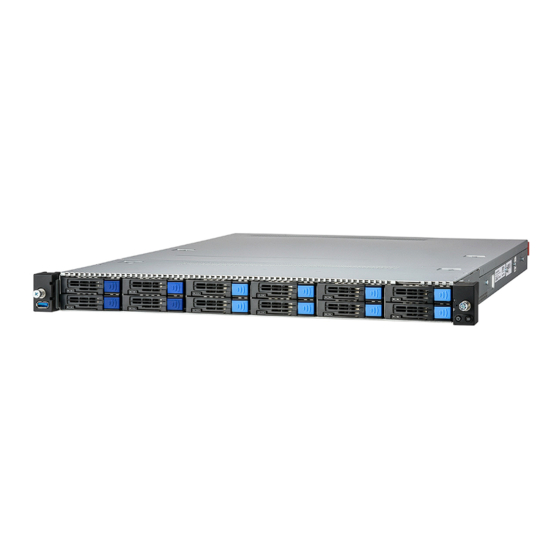
Page 30: About The Product
About the Product The following views show you the product. 1.5.1 System Front View Description Description USB3.2 Gen1 Port (M1725G68-USB Power Button with green & red LED pre-installed) Drive Trays ID Button with blue LED http://www.tyan.com... - Page 31 Front Panel Button and LED (M1724G68-FPB pre-installed) Item Color Behavior System Power On / Green Solid On Power Button Green/Red System Power Off / All Off System Warning / Red Solid On ID Button Blue ID Located / Blue Solid On HDD LED Definitions Drive Status Activity LED (Green)
-
Page 32: System Rear View
1.5.2 System Rear View B7136G68AV4E8HR-2T B7136G68AV4E8HR Description PSU1 PSU0 LAN3 (dedicated for IPMI)+ USB3.2 Gen1 Ports VGA Port Serial Port (COM1) LAN2 (N/A in B7136G68AV4E8HR) LAN1 (N/A in B7136G68AV4E8HR) PCIE Slot Area (PCIe Order #1, #2) ID LED w/ ID LED OCP 3.0 Mezz. -
Page 33: Psu And Lan Led Indications
1.5.3 PSU and LAN LED Indications PSU 1+1 Redundancy Warning LED Indications PSU Status Warning LED 2 PSUs + 2 AC cords are installed when system PS-ON. Greed Solid On 1 PSU + 1 AC cord are installed when system PS-ON. Red Solid On 1+1 PSU redundancy fail. -
Page 34: System Top View
1.5.4 System Top View Description Description M1725G68-USB PSU1 (pre-installed) M1724G68-FPB PSU0 (pre-installed) 2.5” SSD/HDD Trays* (1) 4028 + (5) 4056 fans Riser Card Bracket M1631G68-D-85A-PDB-1 (M7136-R16-1F & M7136-L16-1F (pre-installed) pre-installed) *NOTE: M1299G68A-BPE-12 Drive Backplane Board is pre-installed on B7136G68AE12HR-2T / B7136G68AE12HR SKU. http://www.tyan.com... -
Page 35: Chassis Dimensions
1.5.5 Chassis Dimensions http://www.tyan.com... - Page 36 NOTE http://www.tyan.com...
-
Page 37: Chapter 2: Setting Up
Chapter 2: Setting Up 2.0.1 Before you Begin This chapter explains how to install the CPUs, CPU heatsinks, memory modules, and hard drives. Instructions on inserting add on cards are also given. 2.0.2 Work Area Make sure you have a stable, clean working environment. Dust and dirt can get into components and cause malfunctions. -
Page 38: Precautions
2.0.4 Precautions Components and electronic circuit boards can be damaged by discharges of static electricity. Working on a system that is connected to a power supply can be extremely dangerous. Follow the guidelines below to avoid damage to GC68A-B7136 or injury to yourself. ... -
Page 39: Installing Motherboard Components
Installing Motherboard Components This section describes how to install components on to the motherboard, including CPUs, memory modules and add-on cards. 2.1.1 Removing the Chassis Cover Follow these instructions to remove the GC68A-B7136 chassis cover. 1. Use a screw driver to loosen the captive screw. 2. - Page 40 3. Slide to lift up the rear top cover. 4. Unscrew the front top cover and then slide it forwards to lift it up. http://www.tyan.com...
- Page 41 http://www.tyan.com...
-
Page 42: Replacing The Chassis Cover
2.1.2 Replacing the Chassis Cover Follow these instructions to replace the GC68A-B7136 chassis cover. 1. Place the front top cover on the chassis and slide it backwards. Secure the front top cover with two screws. http://www.tyan.com... - Page 43 2. Place the rear top cover on the chassis and slide it forwards. 3. Adjust the power clips. 4. Use a screw driver to fasten the captive screw on the rear top cover. http://www.tyan.com...
-
Page 44: Installing The Cpu, Heatsink And Air Duct
2.1.3 Installing the CPU, Heatsink and Air Duct Follow the steps below to install the CPU, heatsink and air duct. The GC68A-B7136 supports (2) Intel® Xeon® Eagle Stream (Sapphire Rapids-SP) series CPU. The following installation is based on an Intel LGA4677 socket. 1. - Page 45 3. Carefully flip over to check if the processor is secured. 4. Align the triangle edge of the carrier with the notch on the edge of the heatsink. Then install the carrier on the bottom of the heatsink and make sure the latches are snapped under the edge of the heatsink.
- Page 46 5. Remove the CPU socket cover. 6. Align the heatsink with the CPU socket by the guide pins. Make also sure that the triangle edge of the carrier is aligned correctly with the triangle mark on the CPU socket. Then place the heatsink assembly onto the top of the CPU socket. http://www.tyan.com...
- Page 47 7. Press down on the retention clips to fix the heatsink assembly to the CPU socket. 8. To secure the heatsink assembly, use a T30 Security Torx to tighten the screws in a sequential order (1234). NOTE: When dissembling the heatsink, loosen the screws in reverse order (4321).
- Page 48 9. Align the air duct with its respective slot, and then hook the tab of the air duct to the fan cage. Push the air duct down until it is fully seated. Repeat the same procedures to install another air duct. 10.
-
Page 49: Installing The Memory
2.1.4 Installing the Memory Follow these instructions to install the memory modules onto the motherboard. Unlock the clips. Insert the memory module. Lock the clips. http://www.tyan.com... - Page 50 Memory Population table http://www.tyan.com...
- Page 51 Recommended Memory Population Table Quantity of memory installed Single CPU Installed (Reference Intel Memory Population #610826) √ P0_CHA_DIM0 √ √ √ √ √ √ P0_CHB_DIM0 √ √ √ √ √ P0_CHC_DIM0 √ √ √ √ √ √ P0_CHD_DIM0 √ √ √...
- Page 52 Quantity of memory installed Dual CPU Installed (Reference Intel Memory Population #610826) √ P0_CHA_DIM0 √ √ √ √ √ √ P0_CHB_DIM0 √ √ √ √ √ P0_CHC_DIM0 √ √ √ √ √ √ P0_CHD_DIM0 √ √ √ √ √ P0_CHE_DIM0 √...
-
Page 53: Installing The Expansion Card
2.1.5 Installing the Expansion Card Follow these instructions to install the expansion card. Loosen three screws to take out the riser card bracket. Unscrew to remove the dummy bracket. http://www.tyan.com... - Page 54 Insert the expansion card into the riser card bracket and secure with a screw. Replace the Riser Card Bracket into the chassis. http://www.tyan.com...
-
Page 55: Installing The 2.5" Hard Drive
2.1.6 Installing the 2.5” Hard Drive Follow these instructions to install the 2.5” hard drives for B7136G68AV4E8HR-2T / B7136G68AV4E8HR SKU. 1. Press the locking tab to pull the lever open. 2. Slide the drive tray out. 3. Press the locking tab to pull the tray side rail open. http://www.tyan.com... - Page 56 4. Align the hard drive with the guide pins and install the hard drive into the drive tray. Close the tray side rail. http://www.tyan.com...
- Page 57 5. Insert the drive tray into the chassis and close the lever. http://www.tyan.com...
-
Page 58: Installing The M.2 Card
2.1.7 Installing the M.2 Card Follow these instructions to install the M.2 Card. 1. Take out the M.2 Latch from the AK box. 2. Insert the M.2 latch into the M.2 latch screw hole. 3. Insert the M.2 card into the slot. Close the latch to lock the M.2 card. http://www.tyan.com... - Page 59 4. Insert the second M.2 card into the slot. Pull the latch as shown to lock the M.2 card. http://www.tyan.com...
-
Page 60: Rack Mounting
Rack Mounting After installing the necessary components, GC68A-B7136 can be mounted in a rack using the supplied rack mounting kit. Rack mounting kit Rails x 2 Screw Sacks x 2 2.2.1 Installing the Server in a Rack Follow these instructions to mount the GC68A-B7136 into an industry standard 19”... -
Page 61: Installing Slide Rails To The Rack
2.2.2 Installing Slide Rails to the Rack Take out the rails from the accessory kit. Push the white tab in the direction as the arrow shows to draw out the inner rail. Attach the inner rails to both sides of the chassis. Push the inner rails backward to lock in place. - Page 62 NOTE: Use a screwdriver to slightly push the latch open and then push the inner rail forwards to unlock. Attach the outer rail to the rack. Pull the latch open and align the square stud with the square hole on the rack rail. Please note that the square stud must be fully attached inside the square hole and then close the latch to lock.
- Page 63 Front http://www.tyan.com...
-
Page 64: Rack Mounting The Server
2.2.3 Rack mounting the Server Install the chassis. Draw out the rails half way and then slide the chassis into the rails. Must be done with at least 2 people. Properly place the chassis directly on the rack and install. Slide in the chassis half way to the lock position. - Page 65 Fasten the chassis ear to the front surface of chassis. http://www.tyan.com...
-
Page 66: Removing The Server From Rack
2.2.4 Removing the Server from Rack Release the chassis ears by loosening the screws. Pull out the chassis half way to the lock position. Push the white locking tabs forward to slide the chassis all out from the rack. Caution: Remove the server from the rack carefully. -
Page 67: Chapter 3: Replacing Pre-Installed Components
Chapter 3: Replacing Pre-Installed Components Introduction This chapter explains how to replace the pre-installed components, including the S7136 Motherboard, M1724G68-FPB Front Panel Board, M1725G68-USB Front USB Board, M7136-L16-1F M7136-R16-1F Riser Cards, M1299GC68A-BPE-12 HDD Backplane Board, M1631G68-D-85A-PDB Power Distribution Board, System Fan and Power Supply etc. -
Page 68: Removing The Cover
Removing the Cover Follow Chapter 2.1.1 to remove the cover of GC68A-B7136. Replacing the Power Supply To replace the power supply follow these instructions. 1. Press the latch as shown to pull out the power supply module. 2. Replace a new single power and reinsert it into the power cage following the above steps in reverse. -
Page 69: Replacing The Front Panel Board
Replacing the Front Panel Board Follow these instructions to replace the M1724G68-FPB Front Panel Board. 1. Loosen 3 screws to release the front panel bezel from the chassis. 2. Loosen 2 screws to remove the front panel cage and bracket. 3. -
Page 70: Front Panel Board Features
3.5.1 Front Panel Board Features Front View Rear View M1724G68-FPB Front Panel Board Form Factor 33.5*21*1.6 mm (1) Signal Connector (J1) Integrated I/O (1) PWR Button (1) ID Button http://www.tyan.com... -
Page 71: Replacing The Usb Board
Replacing the USB Board Follow these instructions to replace the M1725G68-USB USB Board. 1. Loosen 3 screws to release the front USB bezel from the chassis. 2. Loosen 2 screws to remove the USB cage and bracket. 3. Disconnect the cable and unscrew the USB Board. 4. -
Page 72: Usb Board Features
3.6.1 USB Board Features Front View Rear View M1725G68-USB Front Panel Board Form Factor 31.9*19.4*1.6 mm (1) Signal Connector (J2) Integrated I/O (1) USB3.0 Connector http://www.tyan.com... -
Page 73: Replacing The Hdd Backplane Board
Replacing the HDD Backplane Board Follow these instructions to replace the M1299G68A-BPE-12 HDD Backplane Boards. 1. First pull the HDD trays out. Disconnect all cables connected to the M1299G68A-BPE-12 HDD Backplane Board. 2. Use a screwdriver to unscrew the M1299G68A-BPE-12 HDD Backplane Board. -
Page 74: Hdd Bp Board Features
3.7.1 HDD BP Board Features Front View Rear View M1299G68A-BPE-12 HDD Backplane Board Form Factor 435*38.3*2.6 mm PCI-E Gen4 12-pot NVMe U.2 BP Board (12) Hot-swap 2.5” NVMe U.2 SSD (2) ATX 2x4-pin Power Connector Integrated I/O (2) 5V connector for DOM (6) Slim-SAS connector (8) Fan connector (1) 2x15-pin Fan Control Connector (J31) -
Page 75: Replacing Power Distribution Board
Replacing Power Distribution Board Follow these instructions to replace the M1631G68-D-85A-PDB Power Distribution Board. 1. Pull the power supply modules slightly away from the chassis. Release cable ties and disconnect all cables from the Power Distribution Board. 2. Unscrew to replace the M1631G68-D-85A-PDB Power Distribution Board. -
Page 76: Power Distribution Board Features
3.8.1 Power Distribution Board Features M1631G68-D-85A-PDB Power Distribution Board Form Factor 171*108*1.6 mm (1) ATX24P (2) ATX8P (1) HDD 4P PWR Specifications (2) DOM 5V PWR (1) PMBUS (2) Micro ATX8P http://www.tyan.com... -
Page 77: Connector Definitions
3.8.2 Connector Definitions Location Definition Power supply slot Power supply slot PWR1 ATX Power 12x2 ATX Power 4x2 ATX Power 4x2 HDD Power 4x1 Micro ATX Power 4x2 Micro ATX Power 4x2 PMBUS DOM_5V_PW1 DOM Power DOM_5V_PW2 DOM Power http://www.tyan.com... -
Page 78: Replacing The Riser Card
Replacing the Riser Card Follow these instructions to replace the M7136G68-L16-1F and M7136G68-R16-1F Riser Cards. 1. Lift up the Riser Card Bracket from the chassis. Unscrew to replace with a new riser card M7136G68-L16-1F. 2. Unscrew to replace with a new riser card M7136G68-R16-1F. 3. -
Page 79: Riser Card Features
3.9.1 Riser card Features M7136G68-L16-1F Riser Card Form Factor W1.26” x D4.88”(W32mmxD124mm) PCI-E x16 Gen5 adapter card Specification (1) PCI-E x16 Gen5 slot support (1) PCI-E x16 Add-on card M7136G68-R16-1F Riser Card Form Factor W1.26” x D4.88”(W32mmxD124mm) PCI-E x16 Gen5 adapter card Specification (1) PCI-E x16 Gen5 slot support (1) PCI-E x16 Add-on card... -
Page 80: Replacing The Fan
3.10 Replacing the Fan Follow these instructions to replace the fan module. 1. Disconnect the fan PWR cable. 2. Lift up the fan module from the chassis. 3. Release the rubber screws and push pins from the fan module. Replace with a new fan and then insert the rubber screws and push pins. - Page 81 4. Place the new fan module into the chassis and reconnect the fan cable. Remember to tie cables after fan replacement. http://www.tyan.com...
-
Page 82: Replacing The Motherboard
3.11 Replacing the Motherboard After removing all of the aforementioned components, follow these instructions to remove the motherboard from the chassis. Release the cable tie and disconnect all cables connected to the mainboard. Remove ten screws securing the motherboard to the chassis. Carefully remove the motherboard from the chassis for replacement. -
Page 83: Chapter 4: Mainboard Information
Unplug the power from your computer power supply and then touch a safely grounded object to release static charge (i.e. power supply case). For the safest conditions, MITAC recommends wearing a static safety wrist strap. (2) Hold the motherboard by its edges and do not touch the bottom of the board, or flex the board in any way. -
Page 84: Board Image
Board Image S7136GMRE This picture is representative of the latest board revision available at the time of publishing. The board you receive may not look exactly like the above picture. http://www.tyan.com... - Page 85 S7136GM2NRE-2T This picture is representative of the latest board revision available at the time of publishing. The board you receive may not look exactly like the above picture. http://www.tyan.com...
-
Page 86: Block Diagram
Block Diagram S7136 Block Diagram http://www.tyan.com... -
Page 87: Mainboard Mechanical Drawing
Mainboard Mechanical Drawing http://www.tyan.com... -
Page 88: Board Parts, Jumpers And Connectors
Board Parts, Jumpers and Connectors This diagram is representative of the latest board revision available at the time of publishing. The board you receive may not look exactly like the above diagram. But for the DIMM number please refer to the above placement for memory installation. For the latest board revision, please visit our web site at http://www.tyan.com. - Page 89 Jumpers & Connectors Connectors 1 Dedicated IPMI port + USB3.2 24 Rear IO_FAN1 (SYSFA4 Gen1 x2 (J13) (SYS_FAN_4)) 25 CPU1_FAN (CPUFAN2 2 Vertical SATA Connector (SATA5) (CPU1_FAN)) 26 Rear IO_FAN2 (SYSFAN3 3 VGA + COM Port (VGA_COM1) (SYS_FAN_3)) 27 22x80mm Connector (M.2#2 4 Vertical SATA Connector (SATA4) (M2_CN2)) 28 22x80mm Connector (M.2#1...
- Page 90 (CN8)) (USB3_FPIO1) 44 36-pin Vertical Mini-SAS HD 21 Vertical MCIO Connector (MCIO7 Connector (SATA 3.0 signals) (CN7)) (SATA_0_3) 45 72-pin Vertical Mini-SAS HD 22 Vertical MCIO Connector (MCIO6 Connector (SATA 3.0 signals) (CN6)) (SATA_0_7) 23 Vertical MCIO Connector (MCIO5 (CN5)) Slots Mini PCIe Slot x24 (J47) Mini PCIe Slot x28 (J8)
- Page 91 FAN1~6 (CPU_FAN1, CPU_FAN2, SYSFAN1~4): 4-pin FAN Connector Signal P12V FAN_TACH FAN_PWM Use this header to connect the cooling fan to your motherboard to keep the system stable and reliable. FPIO_1: Front Panel Pin Header Signal Signal FP_PW_LED_PW FP_ PWER (P3V3_AUX) FP_ID_LED_PW FP_PW_LED_GND FP_ID_LED_N...
- Page 92 FAN_HD1: Fan Connector (Reserved for Barebone) Signal Signal BMC_TACH_FRONT1 BMC_BB_TACH_6 BMC_TACH_FRONT2 BMC_BB_TACH_7 BMC_TACH_FRONT3 BMC_BB_TACH_8 BMC_TACH_REAR1 BMC_BB_TACH_9 BMC_TACH_REAR2 BMC_BB_TACH_10 BMC_PWM_FRONT3 BMC_PWM_FRONT12 SMB_TEMP_SML3_STBY_LV BMC_BB_TACH_11 C3_SDA SMB_TEMP_SML3_STBY_LV BMC_BB_TACH_12 C3_SCL P3V3_AUX BMC_PWM_REAR12 P3V3_AUX BMC_BB_TACH_13 BMC_TACH_CPU1 BMC_BB_TACH_14 BMC_TACH_CPU0 BMC_PWM_BB3 BMC_PWM6 BMC_PWM_CPU0 J3: INTRUDER Header Signal INTRUDER# USB3_FPIO1: Front USB3.2 Gen1 Header...
- Page 93 SPI_TPM (J16): TPM Module Header Signal Signal SPI_PCH_CLK P3V3_AUX RST_PLTRST_TPM_DEDI_R_N FM_TPM_MOD_PRES_N SPI_PCH_MOSI_IO0 IRQ_TPM_SPI_N SPI_PCH_MISO_IO1 P3V3 SPI_PCH_TPM_CS_R_N SATA_SGPIO1: SATA SGPIO Header for SATA4~5 Signal Signal SDATA OUT SLOAD SCLOCK P3V3_AUX HD_COM2: COM Port Header Signal Signal COM2_DCD COM2_DSR COM2_RXD COM2_RTS COM2_TXD COM2_CTS COM2_DTR COM2_NRI...
- Page 94 PWR_BTN1: Power Button Signal Signal PWR_BTN1 RST_BTN1: Reset Button Signal Signal FP_RST_BTN_N CLEAR_BTN1: RTC Reset Button for Clear CMOS Pin 1, 2 Pin 3, 4 RST_N You can reset the CMOS settings by using this button, if you have forgotten your system/setup password or need to clear system BIOS setting.
- Page 95 http://www.tyan.com...
- Page 96 SATA5: 7-pin Vertical SATA Connector PIN Define SATA9_TXP_C Connects to the Serial SATA9_TXN_C ATA ready drives via the Serial ATA cable. SATA9_RXN_C SATA9_RXP_C J1: OCP Connector (Slot) Signal Signal RST_PERST2_L NIC_PWR_GOOD RST_PERST3_L MAIN_PWR_EN PE_WAKE_L SCAN_LOAD_L RBT_ARB_IN SCAN_DATA_IN RBT_ARB_OUT SCAN_DATA_OUT SLOT_ID<1> SCAN_CLK RMII_TX_EN SLOT_ID<0>...
- Page 97 CLK_100M_DP<1> CLK_100M_DP<0> PE_HOST_OCP_RX_DN<15> PE_HOST_OCP_TX_DN<15> PE_HOST_OCP_RX_DP<15> PE_HOST_OCP_TX_DP<15> PE_HOST_OCP_RX_DN<14> PE_HOST_OCP_TX_DN<14> PE_HOST_OCP_RX_DP<14> PE_HOST_OCP_TX_DP<14> PE_HOST_OCP_RX_DN<13> PE_HOST_OCP_TX_DN<13> PE_HOST_OCP_RX_DP<13> PE_HOST_OCP_TX_DP<13> PE_HOST_OCP_RX_DN<12> PE_HOST_OCP_TX_DN<12> PE_HOST_OCP_RX_DP<12> PE_HOST_OCP_TX_DP<12> PE_HOST_OCP_RX_DN<11> PE_HOST_OCP_TX_DN<11> PE_HOST_OCP_RX_DP<11> PE_HOST_OCP_TX_DP<11> PE_HOST_OCP_RX_DN<10> PE_HOST_OCP_TX_DN<10> PE_HOST_OCP_RX_DP<10> PE_HOST_OCP_TX_DP<10> PE_HOST_OCP_RX_DN<9> PE_HOST_OCP_TX_DN<9> PE_HOST_OCP_RX_DP<9> PE_HOST_OCP_TX_DP<9> PE_HOST_OCP_RX_DN<8> PE_HOST_OCP_TX_DN<8> PE_HOST_OCP_RX_DP<8> PE_HOST_OCP_TX_DP<8> PRSNTB1_L PRSNTB0_L PE_HOST_OCP_RX_DN<7> PE_HOST_OCP_TX_DN<7> PE_HOST_OCP_RX_DP<7> PE_HOST_OCP_TX_DP<7> PE_HOST_OCP_RX_DN<6>...
- Page 98 PE_HOST_OCP_RX_DP<0> PE_HOST_OCP_TX_DP<0> USB2_DN USN2_DP PWRBRK_L PRSNTB3_L M2_CN1, M2_CN2: M.2 Connector Signal Signal P3V3 P3V3 CPU0_PE3_M2_RX_R_DN<7> CPU0_PE3_M2_RX_R_DP<7> P3V3_AUX M2_LED_N CPU0_PE3_M2_TX_C_DN<7> P3V3 CPU0_PE3_M2_TX_C_DP<7> P3V3 P3V3 CPU0_PE3_M2_RX_R_DN<6> P3V3 CPU0_PE3_M2_RX_R_DP<6> CPU0_PE3_M2_TX_C_DN<6> CPU0_PE3_M2_TX_C_DP<6> CPU0_PE3_M2_RX_R_DN<5> CPU0_PE3_M2_RX_R_DP<5> CPU0_PE3_M2_TX_C_DN<5> CPU0_PE3_M2_TX_C_DP<5> M2_SMB_CLK CPU0_PE3_M2_RX_R_DN<4> M2_SMB_DAT CPU0_PE3_M2_RX_R_DP<4> M2_SMB_ALERT_N CPU0_PE3_M2_TX_C_DN<4> CPU0_PE3_M2_TX_C_DP<4> M2_PERST_N CLK_100M_M2_DN M2_WAKE_PCIE_N CLK_100M_M2_DP...
- Page 99 MCIO1~8: Vertical MCIO Connector Signal Signal CPU0_PE0_RX_DP<0> CPU0_PE0_TX_DP<0> CPU0_PE0_RX_DN<0> CPU0_PE0_TX_DN<0> CPU0_PE0_RX_DP<1> CPU0_PE0_TX_DP<1> CPU0_PE0_RX_DN<1> CPU0_PE0_TX_DN<1> BP_TYPEC CPU0_PE0_HD_SCL0 WAKE_PCIE_N CPU0_PE0_HD_SDA0 CLK_100M_CPU0_NVME_ RST_NVME1_CPU0_PERST CLK_100M_CPU0_NVME_ CPRSNTA CPU0_PE0_RX_DP<2> CPU0_PE0_TX_DP<2> CPU0_PE0_RX_DN<2> CPU0_PE0_TX_DN<2> CPU0_PE0_RX_DP<3> CPU0_PE0_TX_DP<3> CPU0_PE0_RX_DN<3> CPU0_PE0_TX_DN<3> SATA_0_3: 36-pin Vertical Mini SAS HD Connector (SATA 3.0 signals) Signal Signal PCH_SSATA_0-3_A1...
- Page 100 SATA6G_DMI_TX_C_DN<5> SATA6G_DMI_TX_C_DN<4> SATA6G_DMI_TX_C_DP<7> SATA6G_DMI_TX_C_DP<6> SATA6G_DMI_TX_C_DN<7> SATA6G_DMI_TX_C_DN<6> SATA_0_7: 72-pin Vertical Mini SAS HD Connector (SATA 3.0 signals) Signal Signal PCH_SATA_0-7_A1 SGPIO_SATA0_CLOCK_R SGPIO_SATA0_LOAD_R SATA1_RXP_C SATA0_RXP_C SATA1_RXN_C SATA0_RXN_C SATA3_RXP_C SATA2_RXP_C SATA3_RXN_C SATA2_RXN_C SGPIO_SATA0_DATOUT_R SGPIO_DI_0R SAS0_CTYPE SATA1_TXP_C SATA0_TXP_C SATA1_TXN_C SATA0_TXN_C SATA3_TXP_C SATA2_TXP_C SATA3_TXN_C SATA2_TXN_C NC_PCH_SATA_0-7_A1 SGPIO_SATA1_CLOCK_R SGPIO_SATA1_LOAD_R...
- Page 101 J118: BMC COM Port Jumper Signal Signal BMC_COM2_RXD RXD_2 BMC_COM5_RXD (Default) Pin1-2 closed: BMC COM PORT2 Pin2-3 closed: BMC CONSOLE PORT5 J119: BMC COM Port Jumper Signal Signal BMC_COM2_TXD TXD_2 BMC_COM5_TXD (Default) Pin1-2 closed: BMC COM PORT2 Pin2-3 closed: BMC CONSOLE PORT5 J1_PCH: BIOS Recovery Mode Jumper Pin1 Pin2...
- Page 102 J4_PCH: Manufacture Mode Jumper Pin1 Pin2 Pin3 1K-Pull hi FM_MFG_MODE 10K-Pull down Pin1-2 closed: MFG DISABLE (Default) Pin2-3 closed: MFG ENABLE J5_PCH: BIOS ADVANCE FUNCTIONS Jumper Pin1 Pin2 Pin3 1K-Pull down FM_BIOS_ADV_FUNCTIONS 10K-Pull hi (Default) Pin1-2 closed: Normal Operation Pin2-3 closed: BIOS CORE EXECUTION TREE J6_PCH: CLEAR CMOS Jumper Pin1 Pin2...
- Page 103 J14: System Buzzer Jumper Pin1 Pin2 Pin3 Pin4 VCC5_BZ BUZ_1 BUZ_2 (Default) Pin3-4 closed: Normal Mode Pin2-3 closed: Disable PC Beep Pin1-4 closed: Use the external speaker http://www.tyan.com...
-
Page 104: Led Definitions
LED Definitions Signal P3V3 On board HDD_LED1 HDD LED State Description Blue HDD active blinking Signal P3V3_STBY State Description BMC_LED The LED shuts off when the BMC Heartbeat (D1_BMC) controller cannot be detected or properly initiated The LED blinks per second to Blinking Green indicate that the BMC controller... - Page 105 (D33) HeartBeat P3V3_AUX State Description The LED shuts off when the CPLD controller cannot be detected or properly initiated. The LED blinks per second to Green indicate that the BMC controller is working normally. Signal P3V3_AUX PSU Alert State Description PSMI_LED1 The LED shuts off when the PSU is normal...
-
Page 106: Installing The Processor And Heat Sink
錯誤! 尚未定義書籤。. Check our website at for latest processor support. NOTE: MITAC TYAN is not liable for damage as a result of operating an unsupported configuration. Processor Installation for Intel LGA4677 Socket Follow the steps below to install the processors and heat sinks. - Page 107 1. Align the triangle edge of the carrier with the notch on the edge of the heatsink. Then install the carrier on the bottom of the heatsink and make sure the latches are snapped under the edge of the heatsink. 2.
- Page 108 4. Carefully flip the heatsink assembly. Align the heatsink with the CPU socket by the guide pins. Make also sure that the triangle edge of the carrier is aligned correctly with the triangle mark on the CPU socket. Then place the heatsink assembly onto the top of the CPU socket. 5.
- Page 109 6. To secure the heatsink assembly, use a T30 Security Torx to tighten the screws in a sequential order (1234). NOTE: When disassembling the heatsink, loosen the screws in reverse order (4321). NOTE: A new heatsink comes with pre-applied thermal grease. Once the heatsink has been removed from the processor, you need to clean the processor and heatsink using an alcohol solvent.
-
Page 110: Tips On Installing Motherboard In Chassis
Some chassis include plastic studs instead of metal. Although the plastic studs are usable, MITAC recommends using metal studs with screws that will fasten the motherboard more securely in place. Below is a chart detailing what the most common motherboard studs look like and how they should be installed. - Page 111 http://www.tyan.com...
-
Page 112: Installing The Memory
Installing the Memory Before installing memory, ensure that the memory you have is compatible with the motherboard and processor. Check the TYAN Web site at http://www.tyan.com details of the type of memory recommended for your motherboard. Supports up to 128GB of ECC UDIMM DDR4 2666/2400MHz memory. ... - Page 113 Recommended Memory Population Table Quantity of memory installed Single CPU Installed (Reference Intel Memory Population #610826) √ P0_CHA_DIM0 √ √ √ √ √ √ P0_CHB_DIM0 √ √ √ √ √ P0_CHC_DIM0 √ √ √ √ √ √ P0_CHD_DIM0 √ √ √...
- Page 114 Quantity of memory installed Dual CPU Installed (Reference Intel Memory Population #610826) √ P0_CHA_DIM0 √ √ √ √ √ √ P0_CHB_DIM0 √ √ √ √ √ P0_CHC_DIM0 √ √ √ √ √ √ P0_CHD_DIM0 √ √ √ √ √ P0_CHE_DIM0 √...
- Page 115 Memory Installation Procedure Follow these instructions to install memory modules into the S7136. Unlock the clips as shown in the illustration. Insert the memory module firmly into the socket by gently pressing down until it sits flush with the socket. Lock the clips to secure the memory module into place.
-
Page 116: Attaching Drive Cables
Attaching Drive Cables Attaching Serial ATA Cables S7136 is equipped with fourteen (14) Serial ATA (SATA) channel. Connections for the drives are very simple. There is no need to set Master/Slave jumpers on SATA drives. If you are in need of SATA/SAS cables or power adapters please contact your place of purchase. -
Page 117: Installing Add-In Cards
4.10 Installing Add-In Cards Before installing add-in cards, it’s helpful to know if they are fully compatible with your motherboard. For this reason, we’ve provided the diagrams below, showing the slots that may appear on your motherboard. Simply find the appropriate slot for your add-in card and insert the card firmly. Do not force any add-in cards into any slots if they do not seat in place. -
Page 118: Connecting External Devices
4.11 Connecting External Devices Connecting external devices to the motherboard is an easy task. The motherboard supports a number of different interfaces through connecting peripherals. See the following diagrams for the details. NOTE: Peripheral devices can be plugged straight into any of these ports but software may be required to complete the installation. - Page 119 Intel X710-AT2 10G (supports 2.5G, 5G) LAN LED Color Definition 100/1000 Mbps LAN Link/Activity LED Scheme Description Left LED (Link/Activity) Right LED (Speed) No Link Link Solid Yellow 100 Mbps Active Blinking Yellow Link Solid Green Solid Yellow 1/2.5/5 Gbps Active Blinking Green Solid Yellow...
-
Page 120: Installing The Power Supply
4.12 Installing the Power Supply There are four (4) power connectors on your S7136 motherboard. The S7136 supports EPS 12V power supply. NOTE: You must unplug the power supply before plugging the power cables to motherboard connectors. Warning: The mainboard supports up to 350W CPU TDP with the use of 16AWG... - Page 121 J55 (PWR4): 4-Pin Power Connector Signal Signal VCC12_CPU_OTHERS VCC12_CPU_OTHERS http://www.tyan.com...
-
Page 122: Installing Ocp3.0 Rail Kit
4.13 Installing OCP3.0 Rail Kit 1. Take out the OCP 3.0 Rail Kit and Screw Pack. 2. Install the OCP rail to the chassis. Then secure the rail using 1 screw. 2. Insert the server board into the chassis. 3. Use 9 screws (blue arrow) to secure the server board to the chassis. Then use another screw (red arrow) to secure the server board to OCP rail. -
Page 123: Finishing Up
NOTE 1: To avoid damage, when securing the server board, do not use torque force greater than 5~7 kgf/cm (4.35 ~ 6.09 lb/in). When securing the OCP rail screw, do not use torque force greater than 1.5~2 kgf/cm (1.30 ~ 1.73 lb/in). NOTE 2: Only OCP3.0 below 25W is supported, and the temperature overheating condition under system shutdown (S5 State) must be considered by customer. ... -
Page 124: Chapter 5: Bios Setup
Chapter 5: BIOS Setup About the BIOS The BIOS is the basic input/output system, the firmware on the motherboard that enables your hardware to interface with your software. The BIOS determines what a computer can do without accessing programs from a disk. The BIOS contains all the code required to control the keyboard, display screen, disk drives, serial communications, and a number of miscellaneous functions. -
Page 125: Getting Help
Chipset section unless you are absolutely sure of what you are doing. The Chipset defaults have been carefully chosen either by MITAC or your system manufacturer for best performance and reliability. Even a seemingly small change to the Chipset setup options may cause the system to become unstable or unusable. -
Page 126: Main Menu
Main Menu In this section, you can alter general features such as the date and time. Note that the options listed below are for options that can directly be changed within the Main Setup screen. System Language Choose the system default language. English / Simplified Chinese / Japanese System Date Set the Date. -
Page 127: Advanced Menu
Advanced Menu This section facilitates configuring advanced BIOS options for your system. NOTE: This is a sample screenshot of the Advanced Menu. The HII network drivers displayed here depend on the card(s) you installed and the functions you enabled. Network Stack Configuration Network Stack Settings. - Page 128 Super IO Configuration System Super IO Chip Parameters. Hardware Health Configuration Hardware health Configuration Parameters. PCI Subsystem Settings PCI, PCI-X and PCI Express Settings. NVMe Configuration NVMe Devices Information. Trusted Computing Trusted Computing Settings. CSM Configuration CSM Configuration: Enable/Disable, Option ROM execution settings, etc. Redfish Host Interface Settings Redfish Host Interface Parameters.
-
Page 129: Network Stack Configuration
5.3.1 Network Stack Configuration NOTE: The BIOS will automatically read the onboard LAN controller. Network Stack Enable/Disable UEFI Network Stack. Disabled / Enabled NOTE: The following items are available when Network Stack is set to [Enabled]. Ipv4 PXE Support Enable Ipv4 PXE Boot Support. If disabled IPV4 PXE boot option will not be available. - Page 130 Ipv6 HTTP Support Enable Ipv6 HTTP Boot Support. If disabled IPV6 HTTP boot option will not be available. Disabled / Enabled PXE boot wait time Wait time to press ESC key to abort the PXE boot. Media detect count Number of times the presence of media will be checked. Use either +/- or numeric keys to set the value.
-
Page 131: S5 Rtc Wake Settings
5.3.2 S5 RTC Wake Settings Wake system from S5 Enable or disable System wake on alarm event. Select FixedTime, system will wake on the hr::min::sec specified. Select DynamicTime, System will wake on the current time + Increase minute(s). Disabled / Fixed Time / Dynamic Time When Wake system from S5 is set to [Fixed Time] Wake up hour Select 0-23. -
Page 132: Serial Port Console Redirection
5.3.3 Serial Port Console Redirection Console Redirection / Console Redirection EMS Console redirection enable or disable. Disabled / Enabled Legacy Console Redirection Settings Legacy Console redirection settings. Console Redirection Settings The settings specify how the host computer (which the user is using) will exchange data. - Page 133 5.3.3.1 COM1 Console Redirection Settings Terminal Type Emulation: ANSI: Extended ASCII char set. VT100: ASCII char set. VT100+: Extends VT100 to support color, function keys, etc. VT-UTF8: Uses UTF8 encoding to map Unicode chars onto 1 or more bytes. VT100+ / VT100 / VT-UTF8 / ANSI Bits per Second Select serial port transmission speed.
- Page 134 Stop Bits Stop bits indicate the end of a serial data packet. (A start bit indicates the beginning). The standard setting is 1 stop bit. Communication with slow devices may require more than 1 stop bit. 1 / 2 Flow Control Flow Control can prevent data loss from buffer overflow.
- Page 135 5.3.3.2 COM2 Console Redirection Settings Terminal Type Emulation: ANSI: Extended ASCII char set. VT100: ASCII char set. VT100+: Extends VT100 to support color, function keys, etc. VT-UTF8: Uses UTF8 encoding to map Unicode chars onto 1 or more bytes. VT100+ / VT100 / VT-UTF8 / ANSI Bits per Second Select serial port transmission speed.
- Page 136 Stop Bits Stop bits indicate the end of a serial data packet. (A start bit indicates the beginning). The standard setting is 1 stop bit. Communication with slow devices may require more than 1 stop bit. 1 / 2 Flow Control Flow Control can prevent data loss from buffer overflow.
- Page 137 5.3.3.3 Legacy Console Redirection Settings Legacy Serial Redirection Port Select a COM port to display redirection of Legacy OS and Legacy OPROM Messages. COM1 / COM2 Resolution On Legacy OS, the Number of Rows and Columns supported redirection. 80x24 / 80x25 Redirect After POST When BootLoader is selected, then Legacy Console Redirection is disabled before booting to legacy OS, When Always Enable is selected, then Legacy Console...
- Page 138 5.3.3.4 Serial Port for Out-Of-Band Management/Windows Emergency Services (EMS) Console Redirection Settings Out-of-Band Mgmt Port Microsoft Windows Emergency Management Services (EMS) allows for remote management of a Windows Server OS through a serial port. COM1 / COM2 Terminal Type VT-UTF8 is the preferred terminal type for out-of-band management. The next best choice is VT100+ and then VT100.
- Page 139 Flow Control Flow Control can prevent data loss from buffer overflow. When sending data, if the receiving buffers are full, a ‘stop’ signal can be sent to stop the data flow. Once the buffers are empty, a ‘start’ signal can be sent to restart the flow. Hardware flow control uses two wires to send start/stop signal.
-
Page 140: Pcie Device Configuration
5.3.4 PCIe Device Configuration http://www.tyan.com... - Page 141 5.3.4.1 Option ROM Dispatch Policy LAN1 Option ROM Enable or Disable LAN1 Option ROM Enabled / Disabled LAN2 Option ROM Enable or Disable LAN2 Option ROM Enabled / Disabled PCIE#1~5 Option ROM Enable or Disable Option ROM execution for selected Slot. Enabled / Disabled OCP3.0 Option ROM Enable or Disable Option ROM execution for selected Slot.
-
Page 142: Usb Configuration
5.3.5 USB Configuration Legacy USB Support Enables USB legacy support. AUTO option disables legacy support if no USB devices are connected. DISABLE option will keep USB devices available only for EFI applications. Disabled / Enabled / Auto XHCI Hand-off This is a workaround for OSes without XHCI hand-off support. The XHCI ownership change should be claimed by XHCI driver. - Page 143 USB transfer time-out The time-out value for Control, Bulk and Interrupt transfers. 1 sec / 5 sec / 10 sec / 20 sec Device reset time-out USB mass storage device Start Unit command time-out. 10 sec / 20 sec / 30 sec / 40 sec Device power-up delay Maximum time the device will take before it properly reports itself to the Host Controller.
-
Page 144: Onboard Device Configuration
5.3.6 Onboard Device Configuration Onboard VGA Enable/Disable ASPEED VGA. Enabled / Disabled Primary Display Select active Video type. Onboard / External NMI Function Enable or Disable NMI function. Enabled / Disabled Chassis Intrusion Detection Enabled: When a chassis open event is detected, the BIOS will display the event. Enabled / Disabled http://www.tyan.com... -
Page 145: Super Io Configuration
5.3.7 Super IO Configuration Serial Port 1 Configuration Set Parameters of Serial Port 1 (COMA). http://www.tyan.com... - Page 146 5.3.7.1 Serial Port 1 Configuration Serial Port Enable or disable Serial Port (COM). Enabled / Disabled Device Settings Read only. Change Settings Select an optimal setting for Super IO Device. Auto / IO=3F8h; IRQ=4; / IO=2F8h, IRQ=4; / IO=3E8h, IRQ=4; / IO=2E8h, IRQ=4;...
-
Page 147: Hardware Health Configuration
5.3.8 Hardware Health Configuration Fan Speed Control Fan Speed Control. Automatic / Manual / Full Speed NOTE: Change the Fan Speed Control BIOS setting from [Manual] to [Full Speed] when installing the Nvidia GeForce / Quardro GPU and any VGA card. PWM Minimal Duty Cycle PWM Minimal Duty Cycle (%).This item is available when Fan Speed Control is set to [Manual]. - Page 148 Number of PSU User can select PSU number for needed. 2 / 1 http://www.tyan.com...
- Page 149 5.3.8.1 Sensor Data Register Monitoring http://www.tyan.com...
- Page 150 NOTE: SDR can not be modified. Read only. http://www.tyan.com...
-
Page 151: Pci Subsystem Settings
5.3.9 PCI Subsystem Settings Above 4G Decoding Enables or Disables 64bit capable Devices to be Decoded in Above 4G Address Space (Only if System Supports 64 bit PCI Decoding). Enabled / Disabled SR-IOV Support If system has SR-IOV capable PCIe Devices, this option Enables or Disables Single Root IO Virtualization Support. - Page 152 5.3.9.1 PCI Express Settings Max Payload Set Maximum Payload of PCI Express Device or allow System BIOS to select the value. Auto / 128 Bytes / 256 Bytes / 512 Bytes / 1024 Bytes / 2048 Bytes / 4096 Bytes http://www.tyan.com...
-
Page 153: Nvme Configuration
5.3.10 NVMe Configuration This page shows the Device Name you installed. Press Enter to read the device information. If no NVME device is installed, it shows no NVME device is found. Read only. http://www.tyan.com... -
Page 154: Trusted Computing
5.3.11 Trusted Computing Security Device Support Enables or Disables BIOS support for security device. O.S. will not show Security Device. TCG EFI protocol and INT1A interface will not be available. Enabled / Disabled http://www.tyan.com... -
Page 155: Csm Configuration
5.3.12 CSM Configuration CSM support Enable/Disable CSM Support Enabled / Disabled Option ROM Messages Set display mode for Option ROM Force BIOS / Keep Current Network Controls the execution of UEFI and Legacy PXE OpROM UEFI / Legacy Storage Controls the execution of UEFI and Legacy Storage OpROM UEFI / Legacy http://www.tyan.com... - Page 156 Video Controls the execution of UEFI and Legacy Video OpROM UEFI / Legacy Other PCI devices Determines OpRom execution policy for devices other than network, storage, or video UEFI / Legacy http://www.tyan.com...
-
Page 157: Redfish Host Interface Settings
5.3.13 Redfish Host Interface Settings Redfish Enable/Disable AMI Redfish. Enabled / Disabled BMC Redfish Version / BIOS Redfish Version Read only. IP Address Enter IP address. IP Mask Address Enter IP Mask address. IP Port Enter IP Port. http://www.tyan.com... -
Page 158: Tis Auth Configuration
5.3.14 TIs Auth Configuration Server CA Configuration Press <Enter> to configure Server CA. Client Cert Configuration Press <Enter> to configure Client Cert. http://www.tyan.com... - Page 159 5.3.14.1 Server CA Configuration Enroll Cert Press <Enter> to enroll cert. Delete Cert Press <Enter> to delete cert. http://www.tyan.com...
- Page 160 5.3.14.1.1 Enroll Cert Enroll Cert Using File Enroll Cert Using File. Cert GUID Input digit character in 11111111-2222-3333-4444-1234567890ab format. Commit Changes and Exit Commit Changes and Exit. Discard Changes and Exit Discard Changes and Exit. http://www.tyan.com...
- Page 161 5.3.14.1.2 Delete Cert FE9C6606-8B49-44A3-8B6B-DEA3A0E032 GUID for CERT. Disabled / Enabled http://www.tyan.com...
-
Page 162: Iscsi Configuration
5.3.15 iSCSI Configuration Please follow the instructions to initiate the iSCSI function. Step 1. Select Advanced CSM Configuration Network [UEFI]. Step 2. Select Advanced Network Stack Configuration Network Stack [Enabled] Step 3. Save changes and reboot. Host iSCSI Configuration Host iSCSI Configuration http://www.tyan.com... - Page 163 5.3.15.1 Host iSCSI Configuration iSCSI Initiator Name The worldwide unique name of iSCSI Initiator. Only IQN format is accepted. Enter [iqn.xxx]. xxx ranges from 4 to 223. Add an Attempt Add an Attempt. Delete Attempts Delete one or more attempts. Change Attempt Order Change the order of Attempts using +/- keys.
- Page 164 5.3.15.1.1 Add an Attempt The screen shows the network protocols installed. If no network protocols are installed, the screen displays the message “Necessary network protocols are not available to retrieve….” http://www.tyan.com...
- Page 165 5.3.15.1.2 Delete Attempts Commit Changes and Exit Commit Changes and Exit. Discard Changes and Exit Discard Changes and Exit. http://www.tyan.com...
- Page 166 5.3.15.1.3 Change Attempt Order Commit Changes and Exit Commit Changes and Exit. Discard Changes and Exit Discard Changes and Exit. http://www.tyan.com...
-
Page 167: Vlan Configuration (Mac:xxxxxxxxxxxx)
5.3.16 VLAN Configuration (MAC:xxxxxxxxxxxx) Enter Configuration Menu Press ENTER to enter configuration menu for VLAN configuration. http://www.tyan.com... - Page 168 5.3.16.1 Enter Configuration Menu VLAN ID VLAN ID of new VLAN or existing VLAN, valid value is 0~4094. Priority 802.1Q Priority, valid value is 0~7. Add VLAN Create a new VLAN or update existing VLAN. Remove VLAN Remove selected VLANs. http://www.tyan.com...
-
Page 169: Mac:xxxxxxxxxxxx - Ipv4 Network Configuration
5.3.17 MAC:xxxxxxxxxxxx - IPv4 Network Configuration Configured Indicate whether network address configured successfully or not. Disabled / Enabled Save Changes and Exit Save Changes and Exit. http://www.tyan.com... -
Page 170: Mac:xxxxxxxxxxxx - Ipv6 Network Configuration
5.3.18 MAC:xxxxxxxxxxxx - IPv6 Network Configuration Enter Configuration Menu Press ENTER to enter configuration menu for IPv6 configuration. http://www.tyan.com... - Page 171 5.3.18.1 Enter Configuration Menu Interface ID The 64 bit alternative interface ID for the device. The string is colon separated, e.g. ff:dd:88:66:cc:1:2:3 xx:xx:x:xx:xx:xx:xx:xx DAD Transmit Count The number of consecutive Neighbor Solicitation messages sent while performing Duplicate Address Detection on a tentative address. A value of zero indicates that Duplicate Address Detection is not performed.
-
Page 172: Cpu
Processor Configuration Displays and provides option to change the Processor Settings. Common RefCode Configuration Displays and provides option to change the Common RefCode Settings. Uncore Configuration Displays and provides option to change the Uncore Settings. Memory Configuration Displays and provides option to change the Memory Settings. IIO Configuration Displays and provides option to change the IIO Settings. -
Page 173: Processor Configuration
5.4.1 Processor Configuration Enabled LP (Global) Enabled Logical processor (Software Method to Enabled/Disabled Logical Processor threads) (Hyper-Threading). All LPs / Single LP Enable Intel® TXT Enable Intel® TXT. Disabled / Enabled Hardware Prefetcher =MLC Streamer Prefetcher (MSR 1A4h Bit [0]). Disabled / Enabled Adjacent Cache Prefetch =MLC Spatial Prefetcher (MSR 1A4h Bit [1]). - Page 174 Extended APIC Enabled/Disabled extended APIC support. NOTE: This will enable VT-d automatically if x2APIC is enabled. Disabled / Enabled AES-NI Enabled/Disabled AES-NI support. Disabled / Enabled http://www.tyan.com...
-
Page 175: Common Refcode Configuration
5.4.2 Common RefCode Configuration Numa Enable or Disable Non uniform Memory Access (NUMA). Disabled / Enabled http://www.tyan.com... -
Page 176: Uncore Configuration
5.4.3 Uncore Configuration Uncore General Configuration Displays and provides option to change the Uncore General Settings. http://www.tyan.com... - Page 177 5.4.3.1 Uncore General Configuration Uncore Status Uncore Status Help. Link Speed Mode Select the UPI link speed as either the POR speed (Fast) or default speed (Slow). Slow / Fast Link Frequency Select Allows for selecting the UPI Link Frequency. 9.6GT/s / 10.4GT/s / 11.2GT/s / Auto / Use Per Link Setting Link L0p Enable Enable --- Set the c_l0p_en,...
- Page 178 Link L1 Enable Enable --- Set the c_l1_en, Disable --- Reset it, Auto --- Auto decides based on Si Compatibility. Disabled / Enable / Auto SNC (Sub NUMA) SNC disable will support 1-cluster (XPT/KTI Prefetch enable) 4-IMC may interleave. SNC2 Enable supports 2-clusters SNC and 2-way IMC interleave. SNC4 Enable supports 4-clusters SNC and 1-way IMC interleave.
- Page 179 5.4.3.1.1 Uncore Status Read only http://www.tyan.com...
-
Page 180: Memory Configuration
5.4.4 Memory Configuration Memory Frequency Maximum Memory Frequency Selections in Mhz. If Enforce POR is disabled, user will be able to run at higher frequencies than the memory support (limited by processor support). Do not select Reserved. Auto / 4000 / 4400 / 4800 Memory Topology Displays memory topology with Dimm population information. - Page 181 5.4.4.1 Memory Topology Read only. http://www.tyan.com...
- Page 182 5.4.4.2 Memory RAS Configuration Dynamic ECC Mode Selection Enabled/Disabled Dynamic ECC Mode Selection. Disabled / Enabled Mirror Mode Full Mirror Mode will set entire 1LM memory in system to be mirrored, consequently reducing the memory capacity by half. Partial Mirror Mode will enable the required size of memory to be mirrored.
- Page 183 Patrol Scrub Enable/Disable Patrol Scrub. Disabled / Enabled Patrol Scrub Interval Selects the number of hours (1-24) required to complete full scrub. A value of zero means auto! http://www.tyan.com...
-
Page 184: Iio Configuration
5.4.5 IIO Configuration Intel® VT for Directed I/O (VT-d) Press <Enter> to bring up the Intel® VT for Directed I/O (VT-d) Configuration menu. Intel® VMD Technology Press <Enter> to bring up the Intel® VMD for Volume Management Device Configuration menu. PCIe Hot Plug Enable/Disable PCIe Hot Plug globally. - Page 185 5.4.5.1 Socket 0 Configuration IOU0 (IIO PCIe Port 1) Selects PCIe port Bifurcation for selected slot(s).Fort Format: xDxCxBxA The port can further be x2x2. Auto / x4x4x4x4 / x4x4_x8 / x_x8x4x4 / x_x8x_x8 / x_x_x_x_x16 IOU1 (IIO PCIe Port 2) Selects PCIe port Bifurcation for selected slot(s).Fort Format: xDxCxBxA The port can further be x2x2.
- Page 186 IOU4 (IIO PCIe Port 5) Selects PCIe port Bifurcation for selected slot(s).Fort Format: xDxCxBxA The port can further be x2x2. Auto / x4x4x4x4 / x4x4_x8 / x_x8x4x4 / x_x8x_x8 / x_x_x_x_x16 Port 1A/1C/1E/1G/2A/2E/3A/4A/4C/4E/4G/5A/5C/5E/5G Settings related to PCI Express Ports (0/1A/1B/1C/1D/2A/2B/2C/2D/3A/3B/3C/3D/4A/4B/4C/4D/5A/5B/5C/5D). http://www.tyan.com...
- Page 187 5.4.5.1.1 Port 1A/1C/1E/1G/2A/2E/3A/4A/4C/4E/4G/5A/5C/5E/5G PCI-E Port In auto mode the BIOS will remove the EXP port if there is no device or errors on that device and the device is not HP capable. Disable is used to disable the port and hide its CFG space.
- Page 188 Override Max Link Width Override the max link width that was set by bifurcation. Auto / x1 / x2 / x4 / x8 / x16 PCIE Port DeEmphasis De-Emphasis control (LNKCON2[6]) for this PCIe port. -6.0 dB / -3.5 dB PCI-E ASPM Support This option enables/disables the ASPM (L1) support for the downstream devices.
- Page 189 5.4.5.2 Socket 1 Configuration IOU0 (IIO PCIe Port 1) Selects PCIe port Bifurcation for selected slot(s).Fort Format: xDxCxBxA The port can further be x2x2. Auto / x4x4x4x4 / x4x4_x8 / x_x8x4x4 / x_x8x_x8 / x_x_x_x_x16 IOU1 (IIO PCIe Port 2) Selects PCIe port Bifurcation for selected slot(s).Fort Format: xDxCxBxA The port can further be x2x2.
- Page 190 IOU4 (IIO PCIe Port 5) Selects PCIe port Bifurcation for selected slot(s).Fort Format: xDxCxBxA The port can further be x2x2. Auto / x4x4x4x4 / x4x4_x8 / x_x8x4x4 / x_x8x_x8 / x_x_x_x_x16 Port 1A/2A/2C/2E/3A/4A/4C/4E/4G/5A/5C/5E/5G Settings related to PCI Express Ports (0/1A/1B/1C/1D/2A/2B/2C/2D/3A/3B/3C/3D/4A/4B/4C/4D/5A/5B/5C/5D). http://www.tyan.com...
- Page 191 5.4.5.2.1 Port 1A/2A/2C/2E/3A/4A/4C/4E/4G/5A/5C/5E/5G PCI-E Port In auto mode the BIOS will remove the EXP port if there is no device or errors on that device and the device is not HP capable. Disable is used to disable the port and hide its CFG space.
- Page 192 Override Max Link Width Override the max link width that was set by bifurcation. Auto / x1 / x2 / x4 / x8 / x16 PCIE Port DeEmphasis De-Emphasis control (LNKCON2[6]) for this PCIe port. -6.0 dB / -3.5 dB PCI-E ASPM Support This option enables/disables the ASPM (L1) support for the downstream devices.
- Page 193 5.4.5.3 Intel® VT for Directed I/O (VT-d) Intel® VT for Directed I/O (VT-d) Enable/Disable Intel® Virtualization Technology for Directed I/O (VT-d) by reporting the I/O device assignment to VMM through DMAR ACPI Tables. Disabled / Enabled Pre-boot DMA Protection Enabled DMA Protection in Pre-boot environment (If DMAR table is installed in DXE and If VTD_INFO_PPI is installed in PEI.) Disabled / Enabled PCIe ACSCTL...
- Page 194 Translation Blocking When set, the component blocks all upstream Memory Requests whose Address Translation (AT) field is not set to the default value. Disabled / Enabled P2P Request Redirect This bit determines when the component redirects peer-to-peer Requests upstream. Disabled / Enabled P2P Completion Redirect Determines when the component redirects peer-to-peer completions upstream, applicable only to Read completions whose Relaxed ordering Attribute is clear.
- Page 195 5.4.5.4 Intel® VMD Technology http://www.tyan.com...
- Page 196 5.4.5.4.1 Intel VMD for Volume Management for Socket 0 VMD Config for IOU0 Enable/Disable VMD Enable/Disable VMD in this Stack. Disabled / Enabled VMD Config for IOU1 Enable/Disable VMD Enable/Disable VMD in this Stack. Disabled / Enabled VMD Config for IOU2 Enable/Disable VMD Enable/Disable VMD in this Stack.
- Page 197 VMD Config for IOU4 Enable/Disable VMD Enable/Disable VMD in this Stack. Disabled / Enabled NOTE: The following items are available when Enabled/Disable VMD is set to [Enabled]. VMD Port A/B/C/D/E/F/G/H Enable/Disable Intel® Volume Management Device Technology on specific root port. Disabled / Enabled Hot Plug Capable Enable/Disable Hot Plug for PCIe Root Ports.
- Page 198 5.4.5.4.2 Intel VMD for Volume Management for Socket 1 VMD Config for IOU0 Enable/Disable VMD Enable/Disable VMD in this Stack. Disabled / Enabled VMD Config for IOU1 Enable/Disable VMD Enable/Disable VMD in this Stack. Disabled / Enabled VMD Config for IOU2 Enable/Disable VMD Enable/Disable VMD in this Stack.
- Page 199 VMD Config for IOU4 Enable/Disable VMD Enable/Disable VMD in this Stack. Disabled / Enabled NOTE: The following items are available when Enabled/Disable VMD is set to [Enabled]. VMD Port A/B/C/D/E/F/G/H Enable/Disable Intel® Volume Management Device Technology on specific root port. Disabled / Enabled Hot Plug Capable Enable/Disable Hot Plug for PCIe Root Ports.
-
Page 200: Advanced Power Management Configuration
5.4.6 Advanced Power Management Configuration CPU P State Control P State Control Configuration Sub Menu, include Turbo, XE and etc. Hardware PM State Control Hardware P-State setting. CPU C State Control CPU C State setting. Package C State Control Package C State setting. CPU Advanced PM Tuning Setting Energy Per Bias, Pwr_Ctl, PP0 Current SWLTD, SAPM etc. - Page 201 5.4.6.1 CPU P State Control SpeedStep (Pstates) Enable/Disable EIST (P-States). Disabled / Enabled Boot performance mode Select the performance state that the BIOS will set before OS hand off. Max Performance / Max Efficient / Set by Intel Node Manager Energy Efficient Turbo Energy Efficient Turbo Disable, MSR 0x1FC [19].
- Page 202 CPU Core Flex Ratio (available if CPU Flex Ratio Override is set to [Enabled]) Non-Turbo Mode Processor Core Ratio Multiplier. http://www.tyan.com...
- Page 203 5.4.6.2 Hardware PM State Control Hardware P-States Disable: Hardware chooses a P-state based on OS Request (Legacy P-States). Native Mode: Hardware chooses a P-state based on OS guidance. Out of Band Mode: Hardware autonomously chooses a P-state (no OS guidance). Disabled / Native Mode / Out of Band Mode / Native Mode with No Legacy Support http://www.tyan.com...
- Page 204 5.4.6.3 CPU C State Control CPU C1 auto demotion Allows CPU to automatically demote to C1. Takes effect after reboot. Disabled / Enabled CPU C6 report Enable/Disable CPU C6 (ACPI C3) report to OS. Disabled / Enabled / Auto Enhanced Halt State (C1E) Core C1E auto promotion Control.
- Page 205 5.4.6.4 Package C State Control Package C State Package C State limit. C0/C1 state / C2 state / C6 (non Retention) state / C6 (Retention) state / No Limit / Auto http://www.tyan.com...
- Page 206 5.4.6.5 CPU Advanced PM Tuning Power Performance Tuning Options decides who controls EPB. In OS mode: IA32_ENERGY_PERF_BIAS is used In BIOS mode: ENERGY_PERF_BIAS_CONFIG is used In PECI mode: PCS53 is used OS Controls EPB / BIOS Controls EPB / PECI Controls EPB http://www.tyan.com...
- Page 207 5.4.6.6 CPU Advanced PM Tuning Current Limit Override Disable --- Default, do nothing; Enable, override current limitation in 1/8 A increments. Disabled / Enabled Current Limitation (available if Current Limit Override is set to [Enabled]) Current limitation in 1/8 A increments. This field is locked by VR_CURRENT_CONFIG [LOCK].
- Page 208 5.4.6.7 SOCKET RAPL Config PL1 Limit PL1 Power Limit is Watts. The value may vary from 0 to Fused Value. If the value is 0, the fused value will be programmed. A value greater than fused TDP value will not be programmed.
- Page 209 PL2 Power Limit PL2 Power Limit in Watts. The value may vary from 0 to Fused value. If the value is 0, BIOS programs 120% * TDP. PL2 Time Window PL2 value in seconds. The value may vary from 0 to 0.438. Indicates the time window over which TDP value should be maintained.
-
Page 210: Chipset
Chipset PCH-IO Configuration PCH Parameters. Server ME Configuration Configure Server ME Technology Parameters. http://www.tyan.com... -
Page 211: Pch-Io Configuration
5.5.1 PCH-IO Configuration PCI Express Configuration PCI Express Configuration settings SATA And RST Configuration Device Option Settings Restore AC Power Loss Specify what state to go to when power is re-applied after a power failure (G3 state). Power On / Power Off / Last State http://www.tyan.com... - Page 212 5.5.1.1 PCI Express Configuration PCI Express Root Port 1 ~ Port 16 PCI Express Root Port 1~ Port 16. http://www.tyan.com...
- Page 213 5.5.1.1.1 PCI Express Root Port 1 ~ Port 16 PCI Express Root Port 1~16 Control the PCI Express Root Port. Disabled / Enabled ASPM PCI Express Active State Power Management settings. Disabled / L1 L1 Substates PCI Express L1 Substates settings. Disabled / L1.1 / L1.2 / L1.1 &...
- Page 214 5.5.1.2 SATA And RST Configuration Controller 1 SATA And RST Configuration SATA Controller 1 Device Options Settings. Controller 2 SATA And RST Configuration SATA Controller 2 Device Options Settings. Controller 3 SATA And RST Configuration SATA Controller 3 Device Options Settings. http://www.tyan.com...
- Page 215 5.5.1.2.1 Controller 1 SATA And RST Configuration SATA Controller Enable or Disable SATA Controller. Disabled / Enabled SATA Mode Selection Determines how SATA controller(s) operate. AHCI / RAID Support Aggressive Link Power Management Enables/Disables SALP. Disabled / Enabled Port 4/5/6/7 Enable or Disable SATA Port.
- Page 216 Spin Up Device If enabled for any of ports Staggered Spin Up will be performed and only the drives witch have this option enabled will spin up at boot. Otherwise all drives spin up at boot. Disabled / Enabled SATA Device Type Identify the SATA port is connected to Solid State Drive or Hard disk Drive.
- Page 217 5.5.1.2.2 Controller 2 SATA And RST Configuration SATA Controller Enable or Disable SATA Controller. Disabled / Enabled SATA Mode Selection Determines how SATA controller(s) operate. AHCI / RAID Support Aggressive Link Power Management Enables/Disables SALP. Disabled / Enabled Port 2/3/4/5/6/7 Enable or Disable SATA Port.
- Page 218 Spin Up Device If enabled for any of ports Staggered Spin Up will be performed and only the drives witch have this option enabled will spin up at boot. Otherwise all drives spin up at boot. Disabled / Enabled SATA Device Type Identify the SATA port is connected to Solid State Drive or Hard disk Drive.
- Page 219 5.5.1.2.3 Controller 3 SATA And RST Configuration SATA Controller Enable or Disable SATA Controller. Disabled / Enabled SATA Mode Selection Determines how SATA controller(s) operate. AHCI / RAID Support Aggressive Link Power Management Enables/Disables SALP. Disabled / Enabled Port 0/1/2/3 Enable or Disable SATA Port.
- Page 220 Spin Up Device If enabled for any of ports Staggered Spin Up will be performed and only the drives witch have this option enabled will spin up at boot. Otherwise all drives spin up at boot. Disabled / Enabled SATA Device Type Identify the SATA port is connected to Solid State Drive or Hard disk Drive.
-
Page 221: Server Me Configuration
5.5.2 Server ME Configuration Read only. http://www.tyan.com... -
Page 222: Server Management
Server Management FRB-2 Timer Enable or Disable FRB-2 timer (POST timer). Enabled / Disabled NOTE: FRB-2 Timer timeout and FRB-2 Timer Policy are available when FRB-2 Timer is set to [Enabled]. FRB-2 Timer timeout Enter value Between 3 to 6 min for FRB-2 Timer Expiration value. Not available if FRB-2 Timer is disabled. - Page 223 OS Watchdog Timer If enabled, starts a BIOS timer which can only be shut off by Management Software after the OS loads. Helps determine that the OS successfully loaded or follows the OS Boot Watchdog Timer policy. Enabled / Disabled NOTE: OS Wtd Timer timeout and OS Wtd Timer Policy are available when OS Watchdog Timer is set to [Enabled].
-
Page 224: System Event Log
5.6.1 System Event Log SEL Components Change this to enable or disable all features of System Event Logging during boot. Disabled / Enabled NOTE: When SEL Components is set to [Disabled], the following items are read only. Erase SEL Choose options for erasing SEL. No / Yes, on next reset / Yes, on every reset Log EFI Status Codes Disable the logging of EFI Status Codes or log only error code or only progress code... -
Page 225: Bmc Network Configuration
5.6.2 BMC Network Configuration Configuration Address Source Select the configure LAN channel parameters statically or dynamically (by BIOS or BMC). Unspecified option will not modify any BMC network parameters during BIOS phase. Unspecified / Static / DynamicBmcDhcp / DynamicBmcNonDhcp Management Port 2 Enable/Disable BMC Share NIC. - Page 226 Configuration Address Source Select the configure LAN channel parameters statically or dynamically (by BIOS or BMC). Unspecified option will not modify any BMC network parameters during BIOS phase. Unspecified / Static / DynamicBmcDhcp / DynamicBmcNonDhcp http://www.tyan.com...
-
Page 227: Bmc User Settings
5.6.3 BMC User Settings Add User Press <Enter> to Add a user. Delete User Press <Enter> to Delete a user. Change User Settings Press <Enter> to change User Settings. http://www.tyan.com... - Page 228 5.6.2.1 Add User User Name Enter BMC User Name. User Password Enter New Password to change. Password at least 8 characters. User Access Enable/Disable the BMC User’s Access. Enabled / Disabled Channel No Enter BMC Channel Number. N/A / 1 / 8 User Privilege Limit Enter BMC User Privilege Limit for Selected Channel.
- Page 229 5.6.2.2 Delete User User Name Enter BMC User Name. User Password Enter New Password to change. Password at least 8 characters. http://www.tyan.com...
- Page 230 5.6.2.3 Change User Settings User Name Enter BMC User Name. User Password Enter New Password to change. Password at least 8 characters. Change User Password Enter New Password to change. Password at least 8 characters. User Access Enable/Disable the BMC User’s Access. Enabled / Disabled Channel No Enter BMC Channel Number.
-
Page 231: Security
Security Administrator Password Set administrator password in the Create New Password window. After you key in the password, the Confirm New Password window will pop out to ask for confirmation. User Password Set user password in the Create New Password window. After you key in the password, the Confirm New Password window will pop out to ask for confirmation. -
Page 232: Secure Boot
5.7.1 Secure Boot Secure Boot Secure Boot feature is Active if Secure Boot is Enabled. Platform Key (PK) is enrolled and the System is in User mode. The mode change requires platform reset. Enabled / Disabled Secure Boot Mode Secure Boot mode selector: Standard/Custom. In Custom mode Secure Boot Variables can be configured without authentication. - Page 233 Key Management Enables expert users to modify Secure Boot Policy variables without full authentication. http://www.tyan.com...
- Page 234 5.7.1.1 Key Management Factory Key Provision Install factory default Secure Boot keys after the platform reset and while the System is in Setup mode. Enabled / Disabled Restore Factory Keys Force System to User Mode. Install factory default Secure Boot key databases. Press ‘Yes’...
- Page 235 Enroll Efi Image Allow the image to run in Secure Boot mode. Enroll SHA256 Hash certificate of a PE image into Authorized Signature Database (db). Restore DB defaults Restore DB variable to factory defaults. Press ‘Yes’ to proceed ‘No’ to cancel. Platform Key (PK) Enroll Factory Defaults or load certificates from a file: 1.
- Page 236 b) EFI_CERT_X509 (DER) c) EFI_CERT_RSA2048 (bin) d) EFI_CERT_SHAXXX 2. Authenticated UEFI Variable 3. EFI PE/C0FF Image (SHA256) Key source: Factory, External, Mixed Update / Append Authorized TimeStamps Enroll Factory Defaults or load certificates from a file: 1. Public Key Certificate in: a) EFI_SIGNATURE_LIST b) EFI_CERT_X509 (DER) c) EFI_CERT_RSA2048 (bin)
-
Page 237: Boot
Boot Setup Prompt Timeout Number of seconds to wait for setup activation key. 65535 (0xFFFF) means indefinite waiting. Bootup NumLock State Select the keyboard NumLock state. Off / On Quiet Boot Enable or disable Quiet Boot option. Enabled / Disabled Wait for ‘ESC’... - Page 238 Boot Option Priorities Boot Option #1~#3 Select the system boot order. Device Name / Disabled Delete Boot Option Remove an EFI boot option from the boot order. http://www.tyan.com...
-
Page 239: Delete Boot Option
5.8.1 Delete Boot Option Delete Boot Option Remove an EFI boot option from the boot order. Select one to delete / Device Name http://www.tyan.com... -
Page 240: Save & Exit
Save & Exit Save Changes and Exit Exit system setup after saving the changes. Discard Changes and Exit Exit system setup without saving any changes. Save Changes and Reset Reset the system after saving the changes. Discard Changes and Reset Reset system setup without saving any changes. - Page 241 Restore Defaults Restore/Load Default values for all the setup options. Save as User Defaults Save the changes done so far as User Defaults. Restore User Defaults Restore the User Defaults to all the setup options. Boot Override Read only. http://www.tyan.com...
-
Page 242: Chapter 6: Diagnostics
Chapter 6: Diagnostics NOTE: if you experience problems with setting up your system, always check the following things in the following order: Memory, Video, CPU By checking these items, you will most likely find out what the problem might have been when setting up your system. -
Page 243: Amibios Post Code (Aptio)
AMIBIOS Post Code (Aptio) The POST code checkpoints are the largest set of checkpoints during the BIOS pre-boot process. The following table describes the type of checkpoints that may occur during the POST portion of the BIOS: Checkpoint Ranges Status Code Range Description 0x01 –... - Page 244 Status Code Description 0x0B Cache initialization SEC Error Codes 0x0C – 0x0D Reserved for future AMI SEC error codes 0x0E Microcode not found 0x0F Microcode not found SEC Beep Codes None PEI Phase Status Code Description Progress Codes 0x10 PEI Core is started 0x11 Pre-memory CPU initialization is started 0x12...
- Page 245 Status Code Description 0x35 CPU post-memory initialization. Boot Strap Processor (BSP) selection 0x36 CPU post-memory initialization. System Management Mode(SMM) initialization 0x37 Post-Memory North Bridge initialization is started 0x38 Post-Memory North Bridge initialization (North Bridge module specific) 0x39 Post-Memory North Bridge initialization (North Bridge module specific) 0x3A Post-Memory North Bridge initialization (North Bridge module specific) 0x3B...
- Page 246 Status Code Description 0xEB S3 OS Wake Error 0xEC – 0xEF Reserved for future AMI error codes Recovery Progress Codes 0xF0 Recovery condition triggered by firmware (Auto recovery) 0xF1 Recovery condition triggered by user (Forced recovery) 0xF2 Recovery process started 0xF3 Recovery firmware image is found 0xF4...
- Page 247 Status Code Description 0x72 South Bridge devices initialization 0x73 South Bridge DXE initialization (South Bridge module specific) 0x74 South Bridge DXE initialization (South Bridge module specific) 0x75 South Bridge DXE initialization (South Bridge module specific) 0x76 South Bridge DXE initialization (South Bridge module specific) 0x77 South Bridge DXE initialization (South Bridge module specific) 0x78...
- Page 248 Status Code Description 0xAB Setup Input Wait 0xAC Reserved for ASL (see ASL Status Codes section below) 0xAD Ready To Boot event 0xAE Legacy Boot event 0xAF Exit Boot Services event 0xB0 Runtime Set Virtual Address MAP Begin 0xB1 Runtime Set Virtual Address MAP End 0xB2 Legacy Option ROM initialization 0xB3...
- Page 249 Status Code Description 0x04 System is entering S4 sleep state 0x05 System is entering S5 sleep state 0x10 System is waking up from the S1 sleep state 0x20 System is waking up from the S2 sleep state 0x30 System is waking up from the S3 sleep state 0x40 System is waking up from the S4 sleep state 0xAC...
-
Page 250: Appendix I: How To Recover Uefi Bios
Appendix I: How to recover UEFI BIOS Important Notes: The emergency UEFI BIOS Recovery process is only used to rescue a system with a failed or corrupted BIOS image that fails to boot to an OS. It is not intended to be used as a general purpose BIOS flashing procedure and should not be used as such. - Page 251 The system will boot to BIOS setup. A new menu item will appear at the far right of the screen. Scroll to the 'Recovery' tab, move the curser to “Proceed with flash update” and press the "Enter" key on the keyboard to start the BIOS recovery process.
-
Page 252: Appendix Ii: Installing Io Rail For Ocp Card
Appendix II: Installing IO Rail for OCP Card Follow these instructions to install the IO rail for OCP Card. Here is a sample showing how to install the IO rail for the dual-port LAN card M7062-I599-2T. 1. Take out the OCP rail assembly from the AK box. 2. - Page 253 3. Insert the LAN card into the OCP slot and secure the LAN card to the chassis with four screws. 4. Push forwards the OCP card into the OCP slot. http://www.tyan.com...
-
Page 254: Appendix Iii: Cable Connection Tables
Appendix III: Cable Connection Tables 1. System Fan Connector System Fan to BP M1299G68A-BPE-12 System Fan Connect to -7132 → Fan#1 FAN1 Fan#2 → FAN2 Fan#3 → FAN3 Fan#4 → FAN4 Fan#5 → FAN5 Fan#6 → FAN6 2. FP Control Cable Front Panel Board (FPB) to MB S7136GM2NRE-2T-B M1724G68-FPB... - Page 255 4. Power Cable Power Board (PDB) to MB M1631G68-D-85A- 7136GM2NRE-2T-B/ Connect to PDB-1 S7136GMRE-B 2x12P PWR PWR1 → PWR1 2x4P PWR → 2x4P PWR → → PSMI PSMI_HD1 Power Board (PDB) to BP M1631G68-D-85A- M1299G68A-BPE-12 Connect to PDB-1 -7132 PW2 (BP) 2*4P Micro-Fit Y →...
- Page 256 7. SATA Cable / Slim-SAS Cable BP to MB M1299G68A-BPE- 7136GM2NRE-2T-B/ Connect to 12-7132 S7136GMRE-B Slim-SAS 4i to → SATA 0-7 Mini-SAS HD Slim-SAS 8i to → CN5 / CN6 NVME45 (2)MCIO 4i Slim-SAS 8i to → CN7 / CN8 NVME67 (2)MCIO 4i Slim-SAS 8i to...
- Page 257 NOTE http://www.tyan.com...
-
Page 258: Appendix Iv: Fan And Temp Sensors
Appendix IV: Fan and Temp Sensors This section aims to help readers identify the locations of some specific FAN and Temp Sensors on the motherboard. A table of BIOS Temp sensor name explanation is also included for readers’ reference. Figure 1: Sensor Location NOTE: The red spot indicates the sensor. - Page 259 BIOS Temp Sensor Name Explanation: http://www.tyan.com...
- Page 260 http://www.tyan.com...
- Page 261 BIOS Temp Sensor Name Explanation CPU0_Temp CPU0 Tempterature CPU1_Temp CPU1 Tempterature SYS_Air_Inlet Sensor connected to the Front Panel MB_Air_Inet Temperature of the M/B Air Inlet Area SYS_Air_Outlet Temperature of the System Air Outlet Area PCH_Temp Temperature of the PCH P0_MOSFET Max Temperature of CPU0_MOSFET P1_MOSFET Max Temperature of CPU1_MOSFET...
- Page 262 SYS_FAN_9 Fan Speed of SYS_FAN_9 SYS_FAN_10 Fan Speed of SYS_FAN_10 SYS_FAN_11 Fan Speed of SYS_FAN_11 SYS_FAN_12 Fan Speed of SYS_FAN_12 PSU0_STATUS Current status of PSU0 PSU0_Temp Temperature of PSU0 PSU0_FAN Fan Speed of PSU0 PSU1_STATUS Current status of PSU1 PSU1_Temp Temperature of PSU1 PSU1_FAN Fan Speed of PSU1...
- Page 263 NOTE http://www.tyan.com...
-
Page 264: Appendix V: Fru Parts Table
Appendix V: FRU Parts Table GC68A-B7136 FRU Parts Item Model Number Part Number Picture Description Power Supply FRU-PS-0360 471100000414 POWER SUPPLY 850 W FRU-TS-0270 422T60300001 31000 RPM,40*40*28mm,4PIN fan FRU-TS-0260 336210000073 31000 RPM,40*40*56mm,8PIN fan Heatsink & FRU-TH-0410 343B00900002 Heatsink Cooler Rail FRU-AS-0210 452T60300002 SLIDE RAIL KIT... - Page 265 SlimSAS 8i TO 2*MCIO 4i CABLE, FRU-CS-2070 422B01000002 400 mm SlimSAS 8i TO 2*MCIO 4i CABLE, FRU-CS-2080 422B01000003 500 mm SlimSAS 4i to Mini-SAS HD CABLE, FRU-CS-1360 422T61300009 750 mm FRU-CS-0330 332810000514 A/C Power Cord, L=1800mm,US type FRU-CS-1090 332810000281 A/C Power Cord, L=1830mm,EU type http://www.tyan.com...
-
Page 266: Appendix Vi: Technical Support
With all these convenient resources just a few keystrokes away, users can easily find their latest software and operating system components to keep their systems running as powerful and productive as possible. MITAC also ranks high for its commitment to fast and friendly customer support through email. By offering plenty of options for users, MITAC serves multiple market segments with the industry’s most competitive services to support them. - Page 267 Returning Merchandise for Service During the warranty period, contact your distributor or system vendor FIRST for any product problems. This warranty only covers normal customer use and does not cover damages incurred during shipping or failure due to the alteration, misuse, abuse, or improper maintenance of products.
Need help?
Do you have a question about the TYAN GC68A-B7136 and is the answer not in the manual?
Questions and answers