Table of Contents
Advertisement
Quick Links
Advertisement
Table of Contents

Subscribe to Our Youtube Channel
Related Manuals for MiTAC TYAN TD76-B8058


Summary of Contents for MiTAC TYAN TD76-B8058
- Page 1 TD76-B8058 Tower Server Engineer’s Manual http://www.tyan.com...
- Page 2 MITAC retains the right to make changes to produce descriptions and/or specifications at any time, without notice. In no event will MITAC be held liable for any direct or indirect, incidental or consequential damage, loss of use, loss of data or other malady resulting from errors or inaccuracies of information contained in this document.
- Page 3 FCC Declaration ● Notice for the USA Compliance Information Statement (Supplier's Declaration of Conformity, SDoC) FCC Part 15: This device complies with part 15 of the FCC Rules. This device complies with Part 15 of the FCC Rules. Operation is subject to the following conditions: ‧This device may not cause harmful interference.
- Page 4 Warning This equipment is compliant with Class A of CISPR 32. In a residential environment this equipment may cause radio interference. CAUTION Lithium battery included with this board. Do not puncture, mutilate, or dispose of battery in fire. There will be danger of explosion if battery is incorrectly replaced. Replace only with the same or equivalent type recommended by manufacturer.
- Page 5 How this guide is organized This guide contains the following parts: Chapter 1: Overview This chapter provides an introduction to the TYAN TD76-B8058 barebones and standard parts list, describes the external components, gives an overview of the product from different angles.
- Page 6 Safety and Compliance Information Before installing and using TYAN TD76-B8058, take note of the following precautions: ·Read all instructions carefully. ·Do not place the unit on an unstable surface, cart, or stand. ·Do not block the slots and opening on the unit, which are provided for ventilation.
- Page 7 Safety Information Retain and follow all product safety and operating instructions provided with your equipment. In the event of a conflict between the instructions in this guide and the instructions in equipment documentation, follow the guidelines in the equipment documentation. Observe all warnings on the product and in the operating instructions.
- Page 8 General Precautions · Follow all caution and warning instructions marked on the equipment and explained in the accompanying equipment documentation. Machine Room Environment · Make sure that the area in which you install the system is properly ventilated and climate-controlled. ·...
- Page 9 · Make sure the rack is properly secured to the floor or ceiling. · Make sure the stabilizing feet are attached to the rack if it is a single-rack installation. · Make sure racks are coupled together if it is a multiple-rack installation. ·...
- Page 10 Equipment Power Cords · Use only the power cords and power supply units provided with your system. The system might have one or more power cords. · Plug the power cord into a grounded (earthed) electrical outlet that is easily accessible at all times.
- Page 11 Equipment Repairs and Servicing · The installation of internal options and routine maintenance and service of this product should be performed by individuals who are knowledgeable about the procedures, precautions, and hazards associated with equipment containing hazardous energy levels. · Retain all screws or other fasteners when removing access cover(s). Upon completion of accessing inside the product, refasten access cover with original screws or fasteners.
-
Page 12: Table Of Contents
Table of Contents Chapter 1: Overview............... 15 About the TYAN TD76-B8058 ..........15 Features .................. 16 Standard Parts List ..............19 1.3.1 Box Contents ..............19 1.3.2 Accessories ..............19 About the Product ..............20 ... - Page 13 3.4.2 Connector Definitions ............64 Replacing the Power Supply ..........65 Removing the Motherboard ............ 66 Chapter 4: Mainboard Information ..........67 Board Image ................68 Block Diagram ................ 69 Mainboard Mechanical Drawing ..........70 ...
- Page 14 5.3.18 MAC:xxxxxxxxxxxx - IPv4 Network Configuration ..153 5.3.19 MAC:xxxxxxxxxxxx - IPv6 Network Configuration ..154 5.3.20 VLAN Configuration (MAC:xxxxxxxxxxxx) ....158 5.3.21 MAC:xxxxxxxxxxxx - IPv4 Network Configuration ..160 5.3.22 MAC:xxxxxxxxxxxx - IPv6 Network Configuration ..161 ...
-
Page 15: Chapter 1: Overview
Chapter 1: Overview About the TYAN TD76-B8058 ® Congratulations on your purchase of the TYAN TD76-B8058, a highly optimized ® Server barebone system. The TD76-B8058 is designed to support single AMD EPYC 9004 Series processor and up to 2048GB RDIMM/3DS RDIMM DDR5 4800/3600 memory, providing a rich feature set and incredible performance. -
Page 16: Features
Features TYAN TD76-B8058 (B8058T76X4-270TE4HR) Form Factor 2U Rackmount Chassis Model TD76 Dimension 29.92" x 17.64" x 3.39" (760 x 448 x 86mm) System (D x W x H) Motherboard Name S8058GMNE # Motherboard # The motherboard not sold separately Notification... - Page 17 Connector type D-Sub 15-pin Graphic (per Resolution Up to 1920x1200 blade) Chipset Aspeed AST2600 (1) USB3.2 Gen.1 conn. / (2) USB2.0 Gen.1 ports (@ front) via dongle cable (1) header (COM1) I/O Ports (per blade) (1) D-Sub 15-pin port via dongle cable RJ-45 (1) GbE ports + (1) GbE dedicated for IPMI Button...
- Page 18 NOTE: 1. The specifications are subject to change without prior notice. 2. Please visit our Web site for the latest specifications. http://www.tyan.com...
-
Page 19: Standard Parts List
Standard Parts List This section describes TD76-B8058 package contents and accessories. Open the box carefully and ensure that all components are present and undamaged. The product should arrive packaged as illustrated below. 1.3.1 Box Contents TD76-B8058 Box Contents 2U barebone, (4) E1.S ... -
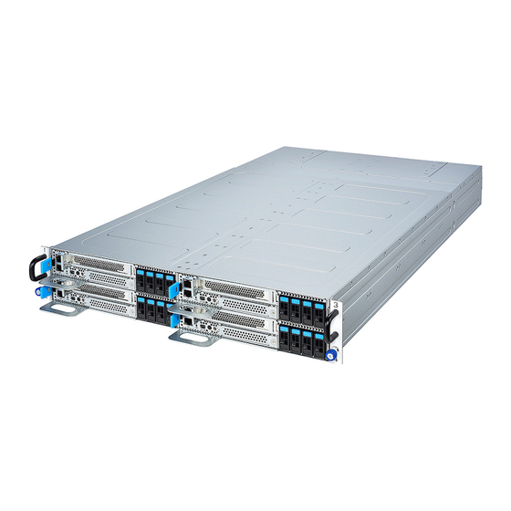
Page 20: About The Product
About the Product The following views show you the product. 1.4.1 System Front View BMC LAN (LAN2) ID LED LAN1 PCIe Slot Warning LED OCP 3.0 Slot HDD LED E1.S #0 Mini Display Port E1.S #1 Power Button w/ LED E1.S #2 ID Button E1.S #3... - Page 21 Front Control Panel (M1727T76-FPB pre-installed) M1727T76-FPB LED Definitions COLOR DESCRIPTION System Power On / Green Solid On Power LED Green System Power Off / All Off System Warning / Red Solid On ID LED Blue ID Located / Blue Solid On Warning LED System Alert Event (BMC Alert Event) HDD present / Green Solid On...
- Page 22 Board Dimension E.1S HDD LED Definitions Active LED (Green) Failure LED (Red) Drive State Drive present, no activity Green Solid On Drive present, with activity Green Blinking Drive Failed Don’t care Red Solid On Drive Identify Don’t care Red Blinking @1 Hz Drive Rebuild Don’t care Red Blinking @4 Hz...
- Page 23 Onboard LAN LED Color Definition two (2) onboard Ethernet ports have green and yellow LEDs to indicate LAN status. The chart below illustrates the different LED states. IPMI 100Mbps/1Gbps Link/activity LED Scheme Left LED Right LED Link/Activity Speed No Link Link Solid Green Linked at 10Mbps...
-
Page 24: System Rear View
1.4.2 System Rear View Power Supply LED Definitions Power Supply Condition LED State +12V output ON and OK Green No AC Power to all power supplies AC present / only +12VSB on (PS off) or PSU in Smart 1Hz Blinking Green standby mode AC cord unplugged or AC lost;... - Page 25 FAN LED Definitions State Description No Definition. FAN1,2,3,4 FAN ACTIVE Green FAN is normal. Blinking Green FAN is abnormal. http://www.tyan.com...
-
Page 26: Node Top View
1.4.3 Node Top View Front Control Panel (M1727T76-FPB pre-installed) E1.S HDD Bays PCIe Slot (M8058T76-R16-1F pre-installed) OCP 3.0 Mezzazine Card Slot http://www.tyan.com... -
Page 27: Chassis Dimensions
1.4.4 Chassis Dimensions http://www.tyan.com... - Page 28 NOTE http://www.tyan.com...
-
Page 29: Chapter 2: Setting Up
Chapter 2: Setting Up 2.0.1 Before you Begin This chapter explains how to install the CPUs, CPU heatsinks, memory modules, and SSD/HDD. Instructions on inserting add on cards are also given. 2.0.2 Work Area Make sure you have a stable, clean working environment. Dust and dirt can get into components and cause malfunctions. -
Page 30: Precautions
2.0.4 Precautions Components and electronic circuit boards can be damaged by discharges of static electricity. Working on a system that is connected to a power supply can be extremely dangerous. Follow the guidelines below to avoid damage to TD76-B8058 or injury to yourself. ... -
Page 31: Installing Motherboard Components
Installing Motherboard Components This section describes how to install components on to the motherboard, including CPUs, memory modules, SSD/HDD and PCI-E card. 2.1.1 Removing the Compute Blade Follow these instructions to pull out the TD76-B8058 single node. 1. Press and hold the locking lever inwards, and then pull the compute blade slightly to disengage it from the chassis. -
Page 32: Reinserting The Compute Blade
2.1.2 Reinserting the Compute Blade 1. Push the locking lever inwards and slide in the compute blade until it clicks. 2. Repeat the same procedures to insert other compute blades into the chassis. http://www.tyan.com... -
Page 33: Installing The Cpu And Heatsink
2.1.3 Installing the CPU and Heatsink Follow the steps below to install the processors and heat sinks. NOTE: Please save and replace the CPU protection cap when returning for service. 1. Use a T20 Torx screwdriver to loosen the screw securing the force frame. NOTE: The force frame will automatically eject after the captive screws are being released. - Page 34 NOTE: A new heatsink comes with pre-applied thermal grease. Once the heatsink has been removed from the processor, you need to clean the processor and heatsink using an alcohol solvent. Then apply new thermal grease before reinstalling the heatsink. 3. Remove the external cap from the rail frame. 4.
- Page 35 5. Carefully close the rail frame with the installed package. Then push both edges of the rail frame firmly until it locks in place. Close the force frame. Then use a T20 Torx screwdriver to tighten the screw to secure the force frame. 7.
-
Page 36: Installing The Expansion Cards
2.1.4 Installing the Expansion Cards Follow the instructions to install the expansion cards. 1. Use a screw driver to loosen the riser bracket. Then remove the riser bracket from the compute blade. 2. Remove the screw securing the PCI dummy bracket, and then remove the PCI dummy bracket. - Page 37 3. Align the add-on card with the riser connector and slide in place. Then secure it with a screw. http://www.tyan.com...
- Page 38 4. Carefully flip the riser bracket and install the riser bracket into its slot on the compute blade. Then tighten the screws to secure the riser bracket in place. http://www.tyan.com...
-
Page 39: Installing The Memory
2.1.5 Installing the Memory Follow these instructions to install the memory modules onto the motherboard. 1. Unlock the clips. 2. Insert the memory module. Follow the recommended memory population table to install the other memory modules. http://www.tyan.com... - Page 40 3. Lock the clips. DIMM Location Memory Type: (16) DIMM slots support (L) RDDR5 5200 w/ ECC (1.1V): - (16) DIMM slots per CPU - (12) memory channels per CPU - (CHA/B/C/D/G/H/I/J) DIMM channel is one DIMM per channel - (CHE/F/K/L) DIMM channel is two DIMM per channel http://www.tyan.com...
- Page 41 Genoa platforms 14L 93mil 14L 74mil 16L 93mil DIMM Type DIMM 0 DIMM 1 high-Dk low-DK high-DK PCB stackup PCB stackup PCB stackup 4800 4800 4800 4000 4400 4400 RDIMM 4400 4800 4800 3600 4000 4000 3600 4000 4000 2SxR 4400 4800 4800...
- Page 42 Recommended Population Table Quantity of memory installed CPU Installed P0_CHA_DIM1 √ √ √ √ √ √ √ √ √ (P0_UMC3_CH_A1) P0_CHB_DIM1 √ √ √ √ √ √ (P0_UMC4_CH_B1) P0_CHC_DIM1 √ √ √ √ √ √ √ (P0_UMC0_CH_C1) P0_CHD_DIM1 √ √ √...
-
Page 43: Installing The E1.S Card
2.1.6 Installing the E1.S Card The TD76-B8058 can support up to four (4) E1.S HDD tray. Follow these instructions to install the E1.S card. 1. Press the locking lever latch and pull the locking lever downwards to its OPEN position. http://www.tyan.com... - Page 44 2. Pull the locking lever to remove the drive tray from its slot. 3. Remove the screws securing the drive tray bracket. Then remove the drive tray bracket. Install an E1.S card onto the drive tray, and then secure it with the screws. http://www.tyan.com...
- Page 45 4. Use a screwdriver to fasten the E1.S HDD tray. 5. Install the drive tray into its slot and press firmly until it is fully seated. 6. Close the locking lever and press it firmly to secure the tray in place. Repeat the same procedures to install other E1.S cards into the drive trays.
-
Page 46: Installing The M.2 Card
2.1.7 Installing the M.2 Card Follow these instructions to install the M.2 Card. 1. Measure the M.2 card length. Insert the M.2 latch into the appropriate hole. 2. Insert the M.2 card into the slot. Make sure the golden finger is fully inserted. http://www.tyan.com... - Page 47 3. Press the M.2 card down and lock the M.2 latch. http://www.tyan.com...
-
Page 48: Installing The Ocp Lan Card
2.1.8 Installing the OCP LAN Card Follow these instructions to install the OCP LAN Card. 1. Unscrew the OCP dummy bracket. 2. Take out the OCP dummy bracket. http://www.tyan.com... - Page 49 3. Insert the OCP LAN card into the OCP3.0 slot. 4. Use a screw driver to fasten the thumb screw. http://www.tyan.com...
-
Page 50: Rack Mounting
2.3.1 Installing the TD76-B8058 in a Rack Follow these instructions to mount the TYAN TD76-B8058 into an industry standard 19” rack. NOTE: Before mounting the TYAN TD76-B8058 in a rack, ensure that all internal components have been installed and that the unit has been fully tested. - Page 51 http://www.tyan.com...
-
Page 52: Rack Mounting The Server
2.2.2 Rack Mounting the Server 1. Lift the unit and then insert the unit onto the outer rails. http://www.tyan.com... - Page 53 2. Push the whole system in. 3. Secure the mounting screw to the rack. http://www.tyan.com...
-
Page 54: Removing The Server From Rack
2.2.3 Removing the Server from Rack 1. Unscrew the chassis. 2. Pull out the chassis forwards to slide the chassis all out from the rack. Caution: Remove the server from the rack carefully. Must be done with at least 2 people. http://www.tyan.com... -
Page 55: Chapter 3: Replacing Pre-Installed Components
Chapter 3: Replacing Pre-Installed Components Introduction This chapter explains how to replace the pre-installed components, including the S8058 Motherboard, M1727T76-FPB Front Panel Board, M8058T76-R16-1F Riser Card, M8058T76-PDB Power Distribution Board, System Fan and Power Supply Unit etc. 3.1.1 Disassembly Flowchart The following flowchart outlines the disassembly procedures. -
Page 56: Removing The Compute Blade
3.1.2 Removing the Compute Blade Before replacing any parts you must remove the compute blade. Follow Section 2.1.1 (page 31) to remove the compute blade of the TD76-B8058. 3.1.3 Replacing Motherboard Components Follow these instructions to replace motherboard components, including the motherboard. -
Page 57: Riser Card Features
3.2.1 Riser Card Features Here shows the M8058T76-R16-1F Riser Card in details. Front view: M8058T76-R16-1F Riser Card Input: (1)PCIe x16 Golder finger Specifications Output: (1) PCIe Gen5 x16 slot Board Dimension http://www.tyan.com... -
Page 58: Replacing The System Fan
Replacing the System Fan Follow these instructions to replace the system fan. 1. Press the locking levers inwards to take out the failed fan. http://www.tyan.com... - Page 59 2. Align the cable with a fan connector with the hole to get it off the fan cage. 3. Replace with a new fan and follow the procedures described earlier in reverse order to install the fan into the fan cage. http://www.tyan.com...
-
Page 60: Replacing The Power Distribution Board
Replacing the Power Distribution Board Follow these instructions to replace the M8058T76-PDB Power Distribution Board. 1. Slightly slide the compute blade forwards. 2. Slightly pull the fan cages and power supply units out. http://www.tyan.com... - Page 61 3. Remove the screws securing the PDB cover to the chassis. 4. Release the PDB cover from the bottom latches. Then remove the cover from the chassis. http://www.tyan.com...
- Page 62 5. Use a screw driver to loosen four screws securing the PDB to the chassis. 6. Unscrew two screw on both sides. 7. Unplug the four cables connected to the PDB. http://www.tyan.com...
-
Page 63: Power Distribution Board Features
3.4.1 Power Distribution Board Features Here shows the M8058T76-PDB Power Distribution Board in details. Front view: Rear view: M8058T76-PDB Power Distribution Board Form Factor: Thickness: 3mm, Layer: 8 layers Four node connectors Four Fan connectors Specifications Four Fan LED connectors ... -
Page 64: Connector Definitions
3.4.2 Connector Definitions Node connector Location node1,node2,node3,node4 PSU connector Location J1,J2 FAN connector Location FAN_1, FAN_2, FAN_3, FAN_4 FAN status LED connector FAN1_LED_CONN, FAN2_LED_CONN, Location FAN3_LED_CONN, FAN4_LED_CONN http://www.tyan.com... -
Page 65: Replacing The Power Supply
Replacing the Power Supply The system has two hot-swap Power Supply Units. Please unplug the power cord before you follow these instructions to replace the power supply units. 1. Press and hold the locking lever inwards, and then pull the Power Supply Unit slightly to disengage it from the chassis. -
Page 66: Removing The Motherboard
Removing the Motherboard Follow these instructions to replace the S8058 Motherboard. 1. Refer to the sections described earlier to remove all cables and components on the motherboard. 2. Unscrew the motherboard. 3. Carefully lift the motherboard from the chassis. 4. Prepare a new motherboard and follow the steps described earlier in reverse order to reinstall the motherboard into the chassis. -
Page 67: Chapter 4: Mainboard Information
Unplug the power from your computer power supply and then touch a safely grounded object to release static charge (i.e. power supply case). For the safest conditions, MITAC recommends wearing a static safety wrist strap. (2) Hold the motherboard by its edges and do not touch the bottom of the board, or flex the board in any way. -
Page 68: Board Image
Board Image S8058 This picture is representative of the latest board revision available at the time of publishing. The board you receive may not look exactly like the above picture. http://www.tyan.com... -
Page 69: Block Diagram
Block Diagram S8058 Block Diagram http://www.tyan.com... -
Page 70: Mainboard Mechanical Drawing
Mainboard Mechanical Drawing http://www.tyan.com... -
Page 71: Board Parts, Jumpers And Connectors
Board Parts, Jumpers and Connectors This diagram is representative of the latest board revision available at the time of publishing. The board you receive may not look exactly like the above diagram. But for the DIMM number please refer to the above placement for memory installation. For the latest board revision, please visit our web site at http://www.tyan.com. - Page 72 Jumpers & Connectors Connectors 1. Front Panel Board Connector 11. Node Power and Signals Connector (FP_CONN) (NOTE_PWR_CONN) 12. U.2 SGPIO Header (reserved only) 2. OCP3.0 Card Connector (OCP3_1) (Hdr) 3. E1.S Connector (E1S_4) 13. TPM Connector (J56) 14. Warm Reset Button 4.
- Page 73 NOTE_PWR_CONN: Node Power and Signals Connector http://www.tyan.com...
- Page 74 Signal Signal P1_1/2/3/4/5/6/7/8 P12V_PSU P2_1/2/3/4/5/6/7/8 P12V_PSU P12V_STBY_MP P12V_PSU P12V_STBY_MP GND(Node present) PDB_FAN4_LED_N PDB_FAN1_LED_N PDB_BMC_PMBUS_C_SCL PDB_FAN2_LED_N PDB_BMC_PMBUS_C_SDA PDB_FAN3_LED_N PDB_BMC_PMBUS_A_SCL NODE_A_BMC_ETXRST_N PDB_BMC_PMBUS_A_SDA PDB_AC_DC_LOSS_N PDB_BMC_PMBUS_B_SCL IRQ_PMBUS_ALERT_N PDB_BMC_PMBUS_B_SDA PDB_PMBUS_RESET_N SMB_IO_PSU_PMBUS_SDA NODE_B_BMC_ETXRST_N SMB_IO_PSU_PMBUS_SCL NODE_C_BMC_ETXRST_N PDB_EXT_RST_N PDB_NODE_ID1 FM_BMC_PCA9538_N PDB_NODE_ID0 FW_PSU_PWR_OFF_N PDB_P12RUN_PWRGD FM_PR_NODE_PRSNT_N FM_PDB_PCA9534_N CPU0_FAN: 4-pin FAN Connector Signal +12V TACH...
- Page 75 PESLOT_PWR_CONN: GPU Card Power Connector Signal Signal P12_RUN_PESLOT P12_RUN_PESLOT P12_RUN_PESLOT P12_RUN_PESLOT HDR: U.2 SGPIO Connector Signal Signal VDD_33_DUAL HP_SCL HP_SDA HP_ALERT J62: 80-PORT Connector Signal Signal VDD_33_RUN ESPI_CS1 RESET# ALERT J56: TPM Header Signal Signal VDD_33_DUAL RESET_N PRSNT_R_N MOSI PIRQ_N MISO VDD_33_RUN CS_N...
- Page 76 PWR_BTN: Power Button Signal Signal FP_PWR_BTN_L COLD_RST_BTN1: Cold Reset Button Signal Signal COLD_RST_BTN_L WARM_RST_BTN: Warm Reset Button Signal Signal WARM_RST_BTN_L http://www.tyan.com...
-
Page 77: Led Definitions
LED Definitions Signal VDD_33_DUAL BMC Heart State Description D1_2 Beat LED The LED shuts off when the BMC cannot be detected or properly initiated. The LED blinks per second to indicate that the Blinking Green BMC is working normally. Signal VDD_33_DUAL State Description... -
Page 78: Installing The Processor And Heat Sink
Check our website at http://www.tyan.com for latest processor support. NOTE: MITAC TYAN is not liable for damage as a result of operating an unsupported configuration. Processor Installation for AMD Socket SP5 Follow the steps below to install the AMD® EPYC 9004 (Genoa) Series processors and heat sinks. - Page 79 3. Remove the external cap from the rail frame. 4. Align and install the carrier frame with package into the slot on the rail frame. Align and install the carrier frame with package into the slot on the rail frame. NOTE: During installation, observe the following: ...
- Page 80 6. Close the force frame. Then use a T20 Torx screwdriver to tighten the screw to secure the force frame. 7. Align and install the CPU heatsink onto the top of the CPU socket. 8. Use a T20 Torx screwdriver to tighten the heatsink screws in a sequential order (123456).
-
Page 81: Tips On Installing Motherboard In Chassis
Some chassis include plastic studs instead of metal. Although the plastic studs are usable, MITAC recommends using metal studs with screws that will fasten the motherboard more securely in place. Below is a chart detailing what the most common motherboard studs look like and how they should be installed. - Page 82 http://www.tyan.com...
-
Page 83: Installing The Memory
Installing the Memory Before installing memory, ensure that the memory you have is compatible with the motherboard and processor. Check the TYAN Web site at http://www.tyan.com details of the type of memory recommended for your motherboard. Supports up to 2048GB RDIMM DDR5 4800 (Follow latest Intel DDR5 Memory POR) ... - Page 84 Genoa platforms 14L 93mil 14L 74mil 16L 93mil DIMM Type DIMM 0 DIMM 1 high-Dk low-DK high-DK PCB stackup PCB stackup PCB stackup 4800 4800 4800 4000 4400 4400 RDIMM 4400 4800 4800 3600 4000 4000 3600 4000 4000 2SxR 4400 4800 4800...
- Page 85 Quantity of memory installed CPU Installed P0_CHA_DIM1 √ √ √ √ √ √ √ √ √ (P0_UMC3_CH_A1) P0_CHB_DIM1 √ √ √ √ √ √ (P0_UMC4_CH_B1) P0_CHC_DIM1 √ √ √ √ √ √ √ (P0_UMC0_CH_C1) P0_CHD_DIM1 √ √ √ √ (P0_UMC5_CH_D1) P0_CHE_DIM0 √...
- Page 86 Memory Installation Procedure Follow these instructions to install memory modules into the S8058. Unlock the clips as shown in the illustration. Insert the memory module firmly into the socket by gently pressing down until it sits flush with the socket. Lock the clips to secure the memory module into place.
-
Page 87: Attaching Drive Cables
Attaching Drive Cables Attaching Serial ATA Cables S8058 is equipped with 4 (four) Serial ATA (SATA) channel. Connections for the drives are very simple. There is no need to set Master/Slave jumpers on SATA drives. If you are in need of SATA/SAS cables or power adapters please contact your place of purchase. -
Page 88: Installing Add-In Cards
4.10 Installing Add-In Cards Before installing add-in cards, it’s helpful to know if they are fully compatible with your motherboard. For this reason, we’ve provided the diagrams below, showing the slots that may appear on your motherboard. Simply find the appropriate slot for your add-in card and insert the card firmly. Do not force any add-in cards into any slots if they do not seat in place. -
Page 89: Connecting External Devices
4.11 Connecting External Devices Connecting external devices to the motherboard is an easy task. The motherboard supports a number of different interfaces through connecting peripherals. See the following diagrams for the details. NOTE: Peripheral devices can be plugged straight into any of these ports but software may be required to complete the installation. -
Page 90: Installing The Power Supply
4.12 Installing the Power Supply There are two (2) power connectors on your S8058 motherboard. The S8058 supports EPS 12V power supply. NOTE: You must unplug the power supply before plugging the power cables to motherboard connectors. Warning: The mainboard supports up to 360W CPU TDP. - Page 91 PDB_BMC_PMBUS_B PDB_PMBUS_RESE _SDA SMB_IO_PSU_PMBUS NODE_B_BMC_ETX _SDA RST_N SMB_IO_PSU_PMBUS NODE_C_BMC_ETX _SCL RST_N PDB_EXT_RST_N PDB_NODE_ID1 FM_BMC_PCA9538_N PDB_NODE_ID0 FW_PSU_PWR_OFF_ PDB_P12RUN_PWR FM_PR_NODE_PRSN FM_PDB_PCA9534_ PESLOT_PWR_CONN: GPU Card Power Connector Signal Signal P12_RUN_PESLOT P12_RUN_PESLOT P12_RUN_PESLOT P12_RUN_PESLOT http://www.tyan.com...
-
Page 92: Finishing Up
4.13 Finishing Up Congratulations on making it this far! You have finished setting up the hardware aspect of your computer. Before closing up your chassis, make sure that all cables and wires are connected properly, especially IDE cables and most importantly, jumpers. -
Page 93: Chapter 5: Bios Setup
Chapter 5: BIOS Setup About the BIOS The BIOS is the basic input/output system, the firmware on the motherboard that enables your hardware to interface with your software. The BIOS determines what a computer can do without accessing programs from a disk. The BIOS contains all the code required to control the keyboard, display screen, disk drives, serial communications, and a number of miscellaneous functions. -
Page 94: Getting Help
Chipset section unless you are absolutely sure of what you are doing. The Chipset defaults have been carefully chosen either by MITAC or your system manufacturer for best performance and reliability. Even a seemingly small change to the Chipset setup options may cause the system to become unstable or unusable. -
Page 95: Main Menu
Main Menu In this section, you can alter general features such as the date and time. Note that the options listed below are for options that can directly be changed within the Main Setup screen. System Language Choose the system default language. English / Simplified Chinese / Japanese System Date Set the Date. -
Page 96: Advanced Menu
Advanced Menu This section facilitates configuring advanced BIOS options for your system. NOTE: This is a sample screenshot of the Advanced Menu. The HII network drivers displayed here depend on the card(s) you installed and the functions you enabled. Network Stack Configuration Network Stack Settings. - Page 97 Super IO Configuration System Super IO Chip Parameters. Hardware Health Configuration Hardware health Configuration Parameters. PCI Subsystem Settings PCI, PCI-X and PCI Express Settings. NVMe Configuration NVMe Devices Information. Trusted Computing Trusted Computing Settings. CSM Computing Enable/Disable, Option ROM execution settings, etc. Redfish Host Interface Settings Redfish Host Interface Parameters.
-
Page 98: Network Stack Configuration
5.3.1 Network Stack Configuration NOTE: The BIOS will automatically read the onboard LAN controller. Network Stack Enable/Disable UEFI Network Stack. Disabled / Enabled NOTE: The following items are available when Network Stack is set to [Enabled]. Ipv4 PXE Support Enable Ipv4 PXE Boot Support. If disabled IPv4 PXE boot support will not be available. - Page 99 Ipv6 HTTP Support Enable Ipv6 HTTP Boot Support. If disabled IPV6 HTTP boot support will not be available. Disabled / Enabled PXE boot wait time Wait time to press ESC key to abort the PXE boot. Media detect count Number of times the presence of media will be checked. Use either +/- or numeric keys to set the value.
-
Page 100: S5 Rtc Wake Settings
5.3.2 S5 RTC Wake Settings Wake system from S5 Enable or disable System wake on alarm event. Select FixedTime, system will wake on the hr::min::sec specified. Select DynamicTime, system will wake on the current time + Increase minute(s). Disabled / Fixed Time / Dynamic Time When Wake system from S5 is set to [Fixed Time] Wake up hour Select 0-23. -
Page 101: Serial Port Console Redirection
.3.3 Serial Port Console Redirection Console Redirection / Console Redirection EMS Console redirection enable or disable. Disabled / Enabled Legacy Console Redirection Settings Legacy Console redirection settings. Console Redirection Settings The settings specify how the host computer (which the user is using) will exchange data. - Page 102 5.3.3.1 COM1 Console Redirection Settings Terminal Type Emulation: ANSI: Extended ASCII char set. VT100: ASCII char set. VT100+: Extends VT100 to support color, function keys, etc. VT-UTF8: Uses UTF8 encoding to map Unicode chars onto 1 or more bytes. VT100+ / VT100 / VT-UTF8 / ANSI Bits per Second Select serial port transmission speed.
- Page 103 Stop Bits Stop bits indicate the end of a serial data packet. (A start bit indicates the beginning). The standard setting is 1 stop bit. Communication with slow devices may require more than 1 stop bit. 1 / 2 Flow Control Flow Control can prevent data loss from buffer overflow.
- Page 104 5.3.3.2 COM2 Console Redirection Settings Terminal Type Emulation: ANSI: Extended ASCII char set. VT100: ASCII char set. VT100+: Extends VT100 to support color, function keys, etc. VT-UTF8: Uses UTF8 encoding to map Unicode chars onto 1 or more bytes. VT100+ / VT100 / VT-UTF8 / ANSI Bits per Second Select serial port transmission speed.
- Page 105 Stop Bits Stop bits indicate the end of a serial data packet. (A start bit indicates the beginning). The standard setting is 1 stop bit. Communication with slow devices may require more than 1 stop bit. 1 / 2 Flow Control Flow Control can prevent data loss from buffer overflow.
- Page 106 5.3.3.3 Legacy Console Redirection Settings Legacy Serial Redirection Port Select a COM port to display redirection of Legacy OS and Legacy OPROM Messages. COM1 / COM2 Resolution On Legacy OS, the Number of Rows and Columns supported redirection. 80x24 / 80x25 Redirect After POST When BootLoader is selected, then Legacy Console Redirection is disabled before booting to legacy OS, When Always Enable is selected, then Legacy Console...
- Page 107 5.3.3.4 Serial Port for Out-Of-Band Management/Windows Emergency Services (EMS) Console Redirection Settings Out-of-Band Mgmt Port Microsoft Windows Emergency Management Services (EMS) allows for remote management of a Windows Server OS through a serial port. COM1 / COM2 Terminal Type VT-UTF8 is the preferred terminal type for out-of-band management. The next best choice is VT100+ and then VT100.
- Page 108 Flow Control Flow Control can prevent data loss from buffer overflow. When sending data, if the receiving buffers are full, a ‘stop’ signal can be sent to stop the data flow. Once the buffers are empty, a ‘start’ signal can be sent to restart the flow. Hardware flow control uses two wires to send start/stop signal.
-
Page 109: Pcie Device Configuration
.3.4 PCIe Device Configuration PCIe Slot Bifurcation PCIe Slot Bifurcation PCIe Slot Speed PCIe Slot Speed. http://www.tyan.com... - Page 110 5.3.4.1 Option ROM Dispatch Policy LAN1 (I210) Enable or Disable LAN1 Option ROM Enabled / Disabled PESLOT1x16 Option ROM Enable or Disable Option ROM execution for selected Slot. Enabled / Disabled OCP3.0 Option ROM Enable or Disable Option ROM execution for selected Slot. Enabled / Disabled http://www.tyan.com...
- Page 111 5.3.4.2 PCIe Slot Bifurcation PESLOT1x16 Selects PCIE port Bifurcation for PESLOT1x16 slot. x16 / x8x8 / x4x4x4x4 OCP3.0 Selects PCIE port Bifurcation for OCP3.0 slot. x16 / x8x8 / x4x4x4x4 http://www.tyan.com...
- Page 112 5.3.4.3 PCIe Slot Speed PESLOT1x16 Maximum Link Speed for PESLOT1x16 slot. Auto / GEN1 (2.5 GT/s) / GEN2 (5 GT/s) / GEN3 (8 GT/s) / GEN4 (16GT/s) / GEN5 (32GT/2) OCP3.0 Maximum Link Speed for OCP3.0 slot. Auto / GEN1 (2.5 GT/s) / GEN2 (5 GT/s) / GEN3 (8 GT/s) / GEN4 (16GT/s) / GEN5 (32GT/2) http://www.tyan.com...
-
Page 113: Usb Configuration
5.3.5 USB Configuration Legacy USB Support Enables USB legacy support. AUTO option disables legacy support if no USB devices are connected. DISABLE option will keep USB devices available only for EFI applications. Disabled / Enabled / Auto XHCI Hand-off This is a workaround for OSes without XHCI hand-off support. The XHCI ownership change should be claimed by XHCI driver. - Page 114 USB transfer time-out The time-out value for Control, Bulk and Interrupt transfers. 1 sec / 5 sec / 10 sec / 20 sec Device reset time-out USB mass storage device Start Unit command time-out. 10 sec / 20 sec / 30 sec / 40 sec Device power-up delay Maximum time the device will take before it properly reports itself to the Host Controller.
-
Page 115: Onboard Device Configuration
5.3.6 Onboard Device Configuration Onboard VGA Enable/Disable ASPEED VGA. Enabled / Disabled LAN1 (I210) LAN Enable/Disable control function. Enabled / Disabled Primary Display Select active Video type. Onboard / External NMI Function Enable or Disable NMI function. Enabled / Disabled Clock Spread Spectrum Enable/Disable Clock Spread Spectrum. -
Page 116: Super Io Configuration
5.3.7 Super IO Configuration Serial Port 1 Configuration Set Parameters of Serial Port 1 (COMA). Serial Port 2 Configuration Set Parameters of Serial Port 2 (COMB). http://www.tyan.com... - Page 117 5.3.7.1 Serial Port 1 Configuration Serial Port Enable or disable Serial Port (COM). Enabled / Disabled Device Settings Read only. Change Settings Select an optimal setting for Super IO Device. Auto ; / IO=3F8h; IRQ=4; / IO=2F8h, IRQ=4; / IO=3E8h, IRQ=4; / IO=2E8h, IRQ=4;...
- Page 118 5.3.7.2 Serial Port 2 Configuration Serial Port Enable or disable Serial Port (COM). Enabled / Disabled Device Settings Read only. Change Settings Select an optimal setting for Super IO Device. Auto ; / IO=3F8h; IRQ=4; / IO=2F8h, IRQ=4; / IO=3E8h, IRQ=4; / IO=2E8h, IRQ=4;...
-
Page 119: Hardware Health Configuration
5.3.8 Hardware Health Configuration Fan Speed Control Fan Speed Control. Automatic / Manual / Full Speed NOTE: When Fan Speed Control is set to [Enabled], the following item appears. PWM Minimal Duty Cycle PWM Minimal Duty Cycle (%).This item is available when Fan Speed Control is set to [Manual]. - Page 120 5.3.8.1 Sensor Data Register Monitoring http://www.tyan.com...
- Page 121 NOTE: SDR can not be modified. Read only. http://www.tyan.com...
-
Page 122: Pci Subsystem Settings
5.3.9 PCI Subsystem Settings Above 4G Decoding Enables or Disables 64bit capable Devices to be Decoded in Above 4G Address Space (Only if System Supports 64 bit PCI Decoding). Enabled / Disabled SR-IOV Support If system has SR-IOV capable PCIe Devices, this option Enables or Disables Single Root IO Virtualization Support. - Page 123 5.3.9.1 PCI Express Settings Max Payload Set Maximum Payload of PCI Express Device or allow System BIOS to select the value. Auto / 128 Bytes / 256 Bytes / 512 Bytes / 1024 Bytes / 2048 Bytes / 4096 Bytes http://www.tyan.com...
-
Page 124: Nvme Configuration
5.3.10 NVMe Configuration If no NVME device is installed, it shows no NVME Device Found. If a NVME device is installed, this page shows the Device Name you installed as shown below. http://www.tyan.com... -
Page 125: Trusted Computing
5.3.11 Trusted Computing Security Device Support Enables or Disables BIOS support for security device. O.S. will not show Security Device. TCG EFI protocol and INT1A interface will not be available. Enabled / Disabled http://www.tyan.com... -
Page 126: Csm Configuration
5.3.12 CSM Configuration CSM support Enable/Disable CSM Support Enabled / Disabled Option ROM Messages Set display mode for Option ROM Force BIOS / Keep Current Network Controls the execution of UEFI and Legacy PXE OpROM UEFI / Legacy Storage Controls the execution of UEFI and Legacy Storage OpROM UEFI / Legacy Video Controls the execution of UEFI and Legacy Video OpROM... - Page 127 Other PCI devices Determines OpRom execution policy for devices other than network, storage, or video UEFI / Legacy http://www.tyan.com...
-
Page 128: Redfish Host Interface Settings
5.3.13 Redfish Host Interface Settings Redfish Enable/Disable AMI Redfish. Enabled / Disabled BMC Redfish Version / BIOS Redfish Version Read only. IP Address Enter IP address. IP Mask Address Enter IP Mask address. IP Port Enter IP Port. http://www.tyan.com... -
Page 129: T1S Auth Configuration
5.3.14 T1s Auth Configuration Server CA Configuration Press <Enter> to configure Server CA. Client Cert Configuration Press <Enter> to configure Client Cert. http://www.tyan.com... - Page 130 5.3.14.1 Server CA Configuration Enroll Cert Press <Enter> to enroll cert. Delete Cert Press <Enter> to delete cert. http://www.tyan.com...
- Page 131 5.3.14.1.1 Enroll Cert Enroll Cert Using File Enroll Cert Using File. Cert GUID Input digit character in 11111111-2222-3333-4444-1234567890ab format. Commit Changes and Exit Commit Changes and Exit. Discard Changes and Exit Discard Changes and Exit. http://www.tyan.com...
- Page 132 5.3.14.1.2 Delete Cert XXXXX GUID for CERT. Disabled / Enabled http://www.tyan.com...
-
Page 133: Iscsi Configuration
5.3.15 iSCSI Configuration Please follow the instructions to initiate the iSCSI function. Step 1. Select Advanced CSM Configuration Network [UEFI]. Step 2. Select Advanced Network Stack Configuration Network Stack [Enabled] Step 3. Save changes and reboot. Attempt Priority Change the priority using +/- keys. - Page 134 5.3.15.1 Attempt Priority Attempt Priority Change the priority using +/- keys. Use arrow keys to select the attempt then press +/- to move the attempt up/down in the attempt order list. Host Attempt / Redfish Attempt Commit Changes and Exit Commit Changes and Exit.
- Page 135 5.3.15.2 Host iSCSI Configuration iSCSI Initiator Name The worldwide unique name of iSCSI Initiator. Only IQN format is accepted. Enter [iqn.xxx]. xxx ranges from 4 to 223. For example: http://www.tyan.com...
- Page 136 Add an Attempt Add an Attempt. Delete Attempts Delete one or more attempts. Change Attempt Order Change the order of Attempts using +/- keys. Use arrow keys to select the attempt then press +/- to move the attempt up/down in the attempt order list. http://www.tyan.com...
- Page 137 5.3.15.1.1 Add an Attempt The screen shows the network protocols installed. If no network protocols are installed, the screen displays the message “Necessary network protocols are not available to retrieve….” MAC xx:xx:xx:xx:xx:xx (Intel® I210 Gigabit Network Co…) PFA: Bus 1 / Dev 0 / Func 0. http://www.tyan.com...
- Page 138 5.3.15.1.1.1 MAC XXX Intel® I210 Gigabit Network Connection iSCSI Attempt Name The human name defined for this attempt. Maximum length is up to 12 characters. Attempt 1 / Attempt # iSCSI Mode Disabled, Enabled, Enabled for MPIO. Disabled / Enabled / Enabled for MPIO Internet Protocol Initiator IP address is system assigned in IP6 mode.
- Page 139 Connection Establishing Timeout The timeout value in milliseconds. The minimum value is 100 milliseconds and the maximum is 20 seconds. Configure ISID OUI-format ISID in 6 bytes, default value is derived from MAC address. Only last 3 bytes are configurable. Example: update 0ABBCCDDEEFF to OABBCCF07901 by input F07901.
- Page 140 5.3.15.1.2 Delete Attempts Commit Changes and Exit Commit Changes and Exit. Discard Changes and Exit Discard Changes and Exit. http://www.tyan.com...
- Page 141 5.3.15.1.3 Change Attempt Order Commit Changes and Exit Commit Changes and Exit. Discard Changes and Exit Discard Changes and Exit. http://www.tyan.com...
-
Page 142: Intel® I210 Gigabit Network Connection
5.3.16 Intel® I210 Gigabit Network Connection Firmware Image Properties View device firmware version information. NIC Configuration Click to configure the network device port. iSCSI Configuration Configure general, initiator and target parameters for iSCSI boot. Device Level Configuration View and configure global device level parameters. Blink LEDs Blink LEDs for a duration up to 15 seconds. - Page 143 5.3.16.1 Firmware Image Properties Read only. http://www.tyan.com...
- Page 144 5.3.16.2 NIC Configuration Legacy Boot Protocol Select a non-UEFI network boot protocol. None / PXE / iSCSI Primary / iSCSI Secondary Wake On LAN Enables power on of the system via LAN. Note that configuring Wake on LAN in the operating system does not change the value of this setting, but does override the behavior of Wake on LAN in OS controlled power states.
- Page 145 5.3.16.3 iSCSI Configuration iSCSI General Parameters Configure general iSCSI parameters. iSCSI Initiator Parameters Configuration of iSCSI initiator parameters (e.g., IP Address, Subnet Mask). iSCSI First Target Parameters Enable connection and configure communication parameters for the iSCSI target. http://www.tyan.com...
- Page 146 5.3.16.3.1 iSCSI General Parameters TCP/IP Parameters via DHCP This option is specific to IPv4. Controls the source of the initiator IP address, DHCP or static assignment. Disabled / Enabled iSCSI Parameters via DHCP (available when TCP/IP Parameters via DHCP is set to [Enabled] Enables the acquisition of iSCSI target parameters from DHCP.
- Page 147 IP Version Controls whether IPv4 or IPv6 network addressing will be used for iSCSI initiator and targets. Currently only IPv4 is supported. IPv4 http://www.tyan.com...
- Page 148 5.3.16.3.2 iSCSI Initiator Parameters IP Address Specifies the IP address of the iSCSI initiator. Subnet Mask Specifies the IPv4 Subnet Mask of the iSCSI initiator. Default Gateway Specifies the Default Gateway of the iSCSI initiator. iSCSI Name Specifies the initiator iSCSI Qualified Name (IQN). CHAP ID / CHAP Secret Read only.
- Page 149 5.3.16.3.3 iSCSI First Target Parameters IP Address Specifies the IP address of the iSCSI target. TCP Port Specifies the TCP Port number of the iSCSI target. Boot LUN Specifies the iSCSI storage target boot Logical Unit Number (LUN). iSCSI Name Specifies the iSCSI Qualified Name (IQN) of the iSCSI Storage target.
- Page 150 5.3.16.4 Device Level Configuration Shared Memory Features Disable usage of reserved memory regions to allow direct assignment of device to guest virtual machines. Enabled / Disabled Active Physical Functions Specify which physical functions are enabled. Disabled functions will not be exposed and their associated ports will be completely shut down.
-
Page 151: Vlan Configuration (Mac:xxxxxxxxxxxx)
5.3.17 VLAN Configuration (MAC:xxxxxxxxxxxx) Enter Configuration Menu Press ENTER to enter configuration menu for VLAN configuration. http://www.tyan.com... - Page 152 5.3.17.1 Enter Configuration Menu VLAN ID VLAN ID of new VLAN or existing VLAN, valid value is 0~4094. Priority 802.1Q Priority, valid value is 0~7. Add VLAN Create a new VLAN or update existing VLAN. Remove VLAN Remove selected VLANs. http://www.tyan.com...
-
Page 153: Mac:xxxxxxxxxxxx - Ipv4 Network Configuration
5.3.18 MAC:xxxxxxxxxxxx - IPv4 Network Configuration Configured Indicate whether network address configured successfully or not. Disabled / Enabled Save Changes and Exit Save Changes and Exit. http://www.tyan.com... -
Page 154: Mac:xxxxxxxxxxxx - Ipv6 Network Configuration
5.3.19 MAC:xxxxxxxxxxxx - IPv6 Network Configuration Enter Configuration Menu Press ENTER to enter configuration menu for IPv6 configuration. http://www.tyan.com... - Page 155 5.3.19.1 Enter Configuration Menu Interface ID The 64 bit alternative interface ID for the device. The string is colon separated, e.g. ff:dd:88:66:cc:1:2:3 xx:xx:x:xx:xx:xx:xx:xx DAD Transmit Count The number of consecutive Neighbor Solicitation messages sent while performing Duplicate Address Detection on a tentative address. A value of zero indicates that Duplicate Address Detection is not performed.
- Page 156 Save Changes and Exit Save Changes and Exit. http://www.tyan.com...
- Page 157 5.3.19.1.1 Advanced Configuration New IPv6 address Manual IP address can only be configured under manual policy. Separate the IP address with blank space to configure more than one address. e.g. 2002::1/64 2002::2/64 New Gateway addresses Gateway IP address can only be configured under manual policy. e.g. 2002::3. Separate the IP address with blank space to configure more than one address.
-
Page 158: Vlan Configuration (Mac:xxxxxxxxxxxx)
5.3.20 VLAN Configuration (MAC:xxxxxxxxxxxx) Enter Configuration Menu Press ENTER to enter configuration menu for VLAN configuration. http://www.tyan.com... - Page 159 5.3.20.1 Enter Configuration Menu VLAN ID VLAN ID of new VLAN or existing VLAN, valid value is 0~4094. Priority 802.1Q Priority, valid value is 0~7. Add VLAN Create a new VLAN or update existing VLAN. Remove VLAN Remove selected VLANs. http://www.tyan.com...
-
Page 160: Mac:xxxxxxxxxxxx - Ipv4 Network Configuration
5.3.21 MAC:xxxxxxxxxxxx - IPv4 Network Configuration Configured Indicate whether network address configured successfully or not. Disabled / Enabled Save Changes and Exit Save Changes and Exit. http://www.tyan.com... -
Page 161: Mac:xxxxxxxxxxxx - Ipv6 Network Configuration
5.3.22 MAC:xxxxxxxxxxxx - IPv6 Network Configuration Enter Configuration Menu Press ENTER to enter configuration menu for IPv6 configuration. http://www.tyan.com... - Page 162 5.3.22.1 Enter Configuration Menu Interface ID The 64 bit alternative interface ID for the device. The string is colon separated, e.g. ff:dd:88:66:cc:1:2:3 xx:xx:x:xx:xx:xx:xx:xx DAD Transmit Count The number of consecutive Neighbor Solicitation messages sent while performing Duplicate Address Detection on a tentative address. A value of zero indicates that Duplicate Address Detection is not performed.
- Page 163 Save Changes and Exit Save Changes and Exit. http://www.tyan.com...
- Page 164 5.3.22.1.1 Advanced Configuration New IPv6 address Manual IP address can only be configured under manual policy. Separate the IP address with blank space to configure more than one address. e.g. 2002::1/64 2002::2/64 New Gateway addresses Gateway IP address can only be configured under manual policy. e.g. 2002::3. Separate the IP address with blank space to configure more than one address.
-
Page 165: Cpu
CPU Configuration CPU Configuration Parameters http://www.tyan.com... -
Page 166: Cpu Configuration
5.4.1 CPU Configuration SVM Mode Enable/disable CPU Virtualization. Enabled / Disabled SVM Mode Control secure memory encryption enable. Enabling both SMEE and SME-MK is not supported. Results in #GP. Enabled / Disabled CPU0 Information View Information related to CPU 0. http://www.tyan.com... - Page 167 5.4.1.1 CPU0 Information Read only. http://www.tyan.com...
-
Page 168: Chipset
Chipset PCIe Compliance Mode PCIe Link Compliance Mode. Disabled / Enabled North Bridge North Bridge Parameters. AMD CBS AMD CBS Setup Page. AMD PBS AMD PBS Setup Page. http://www.tyan.com... -
Page 169: North Bridge Configuration
5.5.1 North Bridge Configuration Memory Information Total Memory: xxxxx MB CPU 0 Information View Memory Information related to CPU 0. http://www.tyan.com... - Page 170 5.5.1.1 CPU 0 Information Read only. http://www.tyan.com...
-
Page 171: Amd Cbs
5.5.2 AMD CBS CPU Common Options CPU Common Options. DF Common Options DF Common Options. UMC Common Options UMC Common Options. NBIO Common Options NBIO Common Options. FCH Common Options FCH Common Options. SOC Miscellaneous Control SOC Miscellaneous Control. http://www.tyan.com... - Page 172 5.5.2.1 CPU Common Options CCD/Core/Thread Enablement CCD/Core/Thread Enablement. Prefetcher settings Prefetcher settings. Platform First Error Handling Enable/Disable PFEH, cloak individual banks, and mask deferred error interrupts from each bank. Enabled / Disabled / Auto Core Performance Boost Disable CPB. Disabled / Auto Global C-state Control Controls IO based C-state generation and DF C-states.
- Page 173 SEV-ES ASID Space Limit SEV-ES ASID Space Limit must enable the SEV-ES ASID Space Limit to (SEV ASID Count +1) can only be used with SEV VMS. If this field is set to (SEV ASID Count +1), all ASIDs are forced to be SEV-ES ASIDs. Hence, the valid values for this field is 1- (SEV ASID Count +1).
- Page 174 5.5.2.1.1 CCD/Core/Thread Enablement CCD Control Sets the number of CCDs to be used. Once this option has been used to remove any CCDs, a POWER CYCLE is required in order for future selections to take effect. Auto / 2 CCDs / 4 CCDs / 6 CCDs / 8 CCDs / 10 CCDs Core Control Sets the number of cores to be used.
- Page 175 5.5.2.1.2 Prefetcher settings L1 Stream HW Prefetcher Option to Enable/Disable L1 Stream HW Prefetcher. Disabled / Enabled / Auto L2 Stream HW Prefetcher Option to Enable/Disable L2 Stream HW Prefetcher. Disabled / Enabled / Auto http://www.tyan.com...
- Page 176 5.5.2.2 DF Common Options Memory Addressing Memory Addressing ACPI ACPI PSP error injection support Enable EINJ support False / True http://www.tyan.com...
- Page 177 5.5.2.2.1 Memory Addressing NUMA nodes per socket Specifies the number of desired NUMA nodes per socket. Zero will attempt to interleave the two sockets together. NPS0 / NPS1 / NPS2 / NPS4 Memory interleaving Allows for disabling memory interleaving. Note that NUMA nodes per socket will be honored regardless of this setting.
- Page 178 5.5.2.2.2 ACPI ACPI SRAT L3 Cache As NUMA Domain Enabled: Each CCX in the system will be declared as a separate NUMA domain. Disabled: Memory Addressing \ NUMA nodes per socket will be declared. Disabled / Enabled / Auto http://www.tyan.com...
- Page 179 5.5.2.3 UMC Common Options DDR Addressing Options DDR Addressing Options. DDR Timing Configuration DDR Timing Configuration. DDR RAS DDR RAS. DDR Security DDR Security. http://www.tyan.com...
- Page 180 5.5.2.3.1 DRAM Time Configuration Chipselect Interleaving Interleave memory blocks across the DRAM chip selects for node 0. Disabled / Auto BankSwapMode BankSwapMode value: 0=Disabled, 1=SwapCPU. Auto / Disabled / Swap CPU http://www.tyan.com...
- Page 181 5.5.2.3.2 DRAM Time Configuration Active Memory Timing Settings Active Memory Timing Settings. Auto / Enabled Memory Target Speed Specifies the memory target speed in MT/s. The valid input is 3200, 3600, 4000, 4400, 4800, 5200, 5600. Value in decimal. Auto / DDR3200 / DDR3600 / DDR4000 / DDR4400 / DDR4800 / DDR5200 / DDR5600 http://www.tyan.com...
- Page 182 5.5.2.3.3 DDR RAS Data Poisoning Enable/Disable data poisoning. Disabled / Enabled / Auto DRAM Boot Time Post Package Repair Enable or Disable DRAM Boot Time Post Package Repair. Enabled / Disabled DRAM Runtime Post Package Repair Enable or Disable DRAM Run Time Post Package Repair. Enabled / Disabled RCD Parity Enable RCD command and address parity.
- Page 183 DRAM Scrubbers DRAM Scrubbers. ECC Configuration ECC Configuration. DRAM Corrected Error Counter Enable Configure DRAM Corrected Error Counter function. Only meaningful when PcdAmdCcxCfgPFEHEnable is TRUE. Disabled / NoLeakMode / LeakMode DRAM Corrected Error Counter Interrupt Enable Enable SMI when DRAM Corrected Error Counter count exceeds the threshold value.
- Page 184 5.5.2.3.3.1 DRAM Scrubbers DRAM ECS Mode 0=AutoECS Mode, 1=ManualECS Mode. AutomaticECS / ManualECS / Auto / DisableECS DRAM Redirect Scrubber Enable Enable/Disable Dram Redirect Scrubber. Disabled / Enabled / Auto DRAM Scrub Redirection Limit Dram ECC Scrub Redirection Limit: 0=8 scrubs, 1=4 scrubs, 2=2 scrubs, 3=1 scrub. 8 Scrubs / 4 Scrubs / 2 Scrubs / 1 Scrub / Auto DRAM Scrub Time Provides a value that is the number of hours to scrub memory.
- Page 185 DRAM Error Threshold Count List of Values: 0=ETC_4, 1=ETC_16, 2=ETC_64, 3=ETC_256 (default – Auto), 4=ETC_1024, 5=ETC_4096. ETC_4 / ETC_16 / ETC_64 / ETC_256 / ETC_1024 / ETC_4096 / Auto DRAM ECS Count Mode 0: RowCount Mode. 1: CodeWord Mode. 0xFF: Auto – ABL decides default as CodeWord Mode. Row Count Mode / Code Word Count Mode / Auto DRAM AutoEcs during Self Refresh 0: AutoEcs Disabled.
- Page 186 5.5.2.3.3.2 ECC Configuration DRAM ECC Symbol Size DRAM ECC Symbol Size (x4/x8/x16). x4 / x16 / Auto DRAM ECC Enable Use this option to enable/disable DRAM ECC. Auto will set ECC to enable. Disabled / Enabled / Auto DRAM UECC Retry DRAM UECC Retry.
- Page 187 5.5.2.3.4 DDR Security TSME Transparent Secure Memory Encryption. Auto / Disabled / Enabled Data Scramble Data Scrambling. Disabled / Enabled / Auto http://www.tyan.com...
- Page 188 5.5.2.4 NBIO Common Options IOMMU Enable/Disable IOMMU. Disabled / Enabled / Auto ACS Enable AER must be enabled for ACS enable to work. Enabled / Disabled / Auto PCIe ARI Support Enables Alternative Routing-ID Interpretation. Disabled / Enabled / Auto PCIe Ten Bit Tag Support Enables PCIe ten bit tags for supported devices.
- Page 189 SMU Common Options SMU Common Options. NBIO RAS Common Options NBIO RAS Common Options. Enable AER Cap Enables Advanced Error Reporting Capability. Disabled / Enabled / Auto http://www.tyan.com...
- Page 190 5.5.2.4.1 SMU Common Options TDP Control Auto=Use the fused TDP Manual=User can set customized TDP Manual / Auto TDP (available if TDP Control is set to [Manual]) TDP [W] (indecimal). PPT Control Auto=Use the fused PPT Manual=User can set customized PPT Manual / Auto PPT (available if PPT Control is set to [Manual]) PPT [W] (indecimal).
- Page 191 PPT Control Auto=Use the fused Determinism Manual=User can set customized Determinism Manual / Auto Determinism Enable (available if Determinism Control is set to [Manual]) [0=Power; 1=Performance] Power / Performance APBDIS Algorithm Performance Boost Disable 0 / 1 / Auto DfPstate DfPstate index to set when APBDIS=1 [0-2] Power Profile Selection DF Pstate selection in the profile policy is overridden by the pstate range BIOS...
- Page 192 5.5.2.4.2 NBIO RAS Common Options NBIO RAS Control (0) Disabled, (1) MCA Disabled / MCA / Auto Egress Poison Severity High Each bit set to 1 enables HIGH severity on the associated IOHC egress port. A bit of 0 indicates LOW severity. 30011 Egress Poison Severity Low Each bit set to 1 enables HIGH severity on the associated IOHC egress port.
- Page 193 NBIO SyncFlood Reporting This value may be used to enable SyncFlood will be reported to APML. When set to FALSE that reporting well be disabled. Enabled / Disabled / Auto Egress Poison Mask High These set the enable mask for masking of errors logged in EGRESS_POISON_STATUS.
- Page 194 ACS RAS Request Value No help string. Direct Request Access Enabled / Request Blocking Enabled / Request Redirect Enabled / Auto NBIO Poison Consumption NBIO Poison Consumption. Auto / Enabled / Disabled Sync Flood on PCIe Fatal Error When ‘Sync Flood on PCIe Fatal Error’ is True, PcdAmdPciesSyncFloodOnFatal should be set to True.
- Page 195 5.5.2.5 FCH Common Options Ac Power Loss Options Ac Power Loss Options. FCH RAS Options FCH RAS Options. http://www.tyan.com...
- Page 196 5.5.2.5.1 AC Power Loss Options AC Loss Control Select Restore AC Power Loss Method. Power Off / Power On / Last State http://www.tyan.com...
- Page 197 5.5.2.5.2 FCH RAS Options Reset After Sync-Flood Enable AB to forward downstream sync-flood message to system controller. Enabled / Disabled / Auto http://www.tyan.com...
- Page 198 5.5.2.6 SOC Miscellaneous Control ABL Console Out Control Enable: Enable ConsoleOut Function for ABL Disable: Disable ConsoleOut Function for ABL Auto: Keep default behavior Disabled / Enabled / Auto PSP error injection support Enable EINJ support. False / True http://www.tyan.com...
-
Page 199: Amd Pbs
5.5.3 AMD PBS AMD CPM RAS related settings. http://www.tyan.com... - Page 200 5.5.3.1 PCIe Root Port UnCorr Error Sev Re Initialize the PCIe AER Uncorrected Error Severity registers of Root Port. 7EF6030 PCIe Device UnCorr Error Sev Reg Initialize the PCIe AER Uncorrected Error Severity registers of PCIe Device. 7EF6030 DRAM Hard Post Package Repair This feature allows spare DRAM rows to replace malfunctioning rows via an in-field repair mechanism.
- Page 201 PCIe Device Corr Err Mask Reg Initialize the PCIe AER Corrected Error Mask register of PCIe Device. 1000 PCIe Device UnCorr Err Mask Reg Initialize the PCIe AER Uncorredted Error Mask register of PCIe Device. 100000 http://www.tyan.com...
-
Page 202: Server Management
Server Management FRB-2 Timer Enable or Disable FRB-2 timer (POST timer). Enabled / Disabled NOTE: FRB-2 Timer timeout and FRB-2 Timer Policy are available when FRB-2 Timer is set to [Enabled]. FRB-2 Timer timeout Enter value Between 3 to 6 min for FRB-2 Timer Expiration value. Not available if FRB-2 Timer is disabled. - Page 203 OS Watchdog Timer If enabled, starts a BIOS timer which can only be shut off by Management Software after the OS loads. Helps determine that the OS successfully loaded or follows the OS Boot Watchdog Timer policy. Enabled / Disabled NOTE: OS Wtd Timer timeout and OS Wtd Timer Policy are available when OS Watchdog Timer is set to [Enabled].
-
Page 204: System Event Log
5.6.1 System Event Log SEL Components Change this to enable or disable all features of System Event Logging during boot. Disabled / Enabled NOTE: When SEL Components is set to [Disabled], the following items are read only. Erase SEL Choose options for erasing SEL. No / Yes, on next reset / Yes, on every reset Log EFI Status Codes Disable the logging of EFI Status Codes or log only error code or only progress code... -
Page 205: Bmc Network Configuration
5.6.2 BMC Network Configuration Configure IPv4 support Management Port 1 Configuration Address Source Select the configure LAN channel parameters statically or dynamically (by BIOS or BMC). Unspecified option will not modify any BMC network parameters during BIOS phase. Unspecified / Static / DynamicBmcDhcp / DynamicBmcNonDhcp Management Port 2 Enable/Disable BMC Share NIC. - Page 206 Configuration Address Source Select the configure LAN channel parameters statically or dynamically (by BIOS or BMC). Unspecified option will not modify any BMC network parameters during BIOS phase. Unspecified / Static / DynamicBmcDhcp / DynamicBmcNonDhcp Management Port 2 IPv6 Support Enable or Disable LAN1 IPV6 Support.
-
Page 207: Bmc User Settings
5.6.3 BMC User Settings Add User Press <Enter> to Add a user. Delete User Press <Enter> to Delete a user. Change User Settings Press <Enter> to change User Settings. http://www.tyan.com... - Page 208 5.6.2.1 Add User User Name Enter BMC User Name. User Password Enter New Password to change. Password at least 8 characters. User Access Enable/Disable the BMC User’s Access. Enabled / Disabled Channel No Enter BMC Channel Number. N/A / 1 / 8 User Privilege Limit Enter BMC User Privilege Limit for Selected Channel.
- Page 209 5.6.2.2 Delete User User Name Enter BMC User Name. User Password Enter New Password to change. Password at least 8 characters. http://www.tyan.com...
- Page 210 5.6.2.3 Change User Settings User Name Enter BMC User Name. User Password Enter New Password to change. Password at least 8 characters. Change User Password Enter New Password to change. Password at least 8 characters. User Access Enable/Disable the BMC User’s Access. Enabled / Disabled Channel No Enter BMC Channel Number.
-
Page 211: Security
Security Administrator Password Set administrator password in the Create New Password window. After you key in the password, the Confirm New Password window will pop out to ask for confirmation. User Password Set user password in the Create New Password window. After you key in the password, the Confirm New Password window will pop out to ask for confirmation. -
Page 212: Secure Boot
5.7.1 Secure Boot Secure Boot Secure Boot feature is Active if Secure Boot is Enabled. Platform Key (PK) is enrolled and the System is in User mode. The mode change requires platform reset. Enabled / Disabled Secure Boot Mode Secure Boot mode options: Standard/Custom. In Custom mode, Secure Boot Policy variables can be configured by a physically present user without full authentication. - Page 213 5.7.1.1 Key Management Factory Key Provision Install factory default Secure Boot keys after the platform reset and while the System is in Setup mode. Enabled / Disabled Restore Factory Keys Force System to User Mode. Install factory default Secure Boot key databases. Press ‘Yes’...
- Page 214 Export Secure Boot variables Copy NVRAM content of Secure Boot variables to files in a root folder on a file system device. Platform Key (PK) Enroll Factory Defaults or load certificates from a file: 1. Public Key Certificate in: a) EFI_SIGNATURE_LIST b) EFI_CERT_X509 (DER) c) EFI_CERT_RSA2048 (bin) d) EFI_CERT_SHAXXX...
- Page 215 Forbidden Signatures Enroll Factory Defaults or load certificates from a file: 1. Public Key Certificate in: a) EFI_SIGNATURE_LIST b) EFI_CERT_X509 (DER) c) EFI_CERT_RSA2048 (bin) d) EFI_CERT_SHAXXX 2. Authenticated UEFI Variable 3. EFI PE/C0FF Image (SHA256) Key source: Factory, External, Mixed Update / Append Authorized TimeStamps Enroll Factory Defaults or load certificates from a file:...
-
Page 216: Boot
Boot Setup Prompt Timeout Number of seconds to wait for setup activation key. 65535 (0xFFFF) means indefinite waiting. Bootup NumLock State Select the keyboard NumLock state. Off / On Quiet Boot Enable or disable Quiet Boot option. Enabled / Disabled Endless Boot Enable or disable Endless Boot. - Page 217 Boot Option Priorities Boot Option #1~#2 Select the system boot order. Device Name / Disabled USB Device BBS Priorities Set the order of the legacy devices in this group. Delete Boot Option Remove an EFI boot option from the boot order. http://www.tyan.com...
-
Page 218: Usb Device Bbs Priorities
5.8.1 USB Device BBS Priorities Boot Option #1 Sets the system boot order. Device Name#1 / Device Name#2 / Disabled Boot Option #2 Sets the system boot order. Device Name #1 / Device Name#2 / Disabled http://www.tyan.com... -
Page 219: Delete Boot Option
5.8.2 Delete Boot Option Delete Boot Option Remove an EFI boot option from the boot order. Select one to delete / Device Name http://www.tyan.com... -
Page 220: Save & Exit
Save & Exit Save Changes and Exit Exit system setup after saving the changes. Discard Changes and Exit Exit system setup without saving any changes. Save Changes and Reset Reset the system after saving the changes. Discard Changes and Reset Reset system setup without saving any changes. - Page 221 Save as User Defaults Save the changes done so far as User Defaults. Restore User Defaults Restore the User Defaults to all the setup options. Boot Override Read only. http://www.tyan.com...
- Page 222 NOTE http://www.tyan.com...
-
Page 223: Chapter 6: Diagnostics
Chapter 6: Diagnostics NOTE: if you experience problems with setting up your system, always check the following things in the following order: Memory, Video, CPU By checking these items, you will most likely find out what the problem might have been when setting up your system. -
Page 224: Amibios Post Code (Aptio)
AMIBIOS Post Code (Aptio) The POST code checkpoints are the largest set of checkpoints during the BIOS pre-boot process. The following table describes the type of checkpoints that may occur during the POST portion of the BIOS: Checkpoint Ranges Status Code Range Description 0x01 –... - Page 225 SEC Error Codes 0x0C – 0x0D Reserved for future AMI SEC error codes 0x0E Microcode not found 0x0F Microcode not found SEC Beep Codes None PEI Phase Status Code Description Progress Codes 0x10 PEI Core is started 0x11 Pre-memory CPU initialization is started 0x12 Pre-memory CPU initialization (CPU module specific) 0x13...
- Page 226 Status Code Description 0x38 Post-Memory North Bridge initialization (North Bridge module specific) 0x39 Post-Memory North Bridge initialization (North Bridge module specific) 0x3A Post-Memory North Bridge initialization (North Bridge module specific) 0x3B Post-Memory South Bridge initialization is started 0x3C Post-Memory South Bridge initialization (South Bridge module specific) 0x3D Post-Memory South Bridge initialization (South Bridge module specific) 0x3E...
- Page 227 Recovery Progress Codes 0xF0 Recovery condition triggered by firmware (Auto recovery) 0xF1 Recovery condition triggered by user (Forced recovery) 0xF2 Recovery process started 0xF3 Recovery firmware image is found 0xF4 Recovery firmware image is loaded 0xF5 – 0xF7 Reserved for future AMI progress codes Recovery Error Codes 0xF8 Recovery PPI is not available...
- Page 228 Status Code Description 0x75 South Bridge DXE initialization (South Bridge module specific) 0x76 South Bridge DXE initialization (South Bridge module specific) 0x77 South Bridge DXE initialization (South Bridge module specific) 0x78 ACPI module initialization 0x79 CSM initialization 0x7A – 0x7F Reserved for future AMI DXE codes 0x80 –...
- Page 229 Status Code Description 0xAE Legacy Boot event 0xAF Exit Boot Services event 0xB0 Runtime Set Virtual Address MAP Begin 0xB1 Runtime Set Virtual Address MAP End 0xB2 Legacy Option ROM initialization 0xB3 System Reset 0xB4 USB hot plug 0xB5 PCI bus hot plug 0xB6 Clean-up of NVRAM 0xB7...
- Page 230 Status Code Description 0x20 System is waking up from the S2 sleep state 0x30 System is waking up from the S3 sleep state 0x40 System is waking up from the S4 sleep state 0xAC System has transitioned into ACPI mode. Interrupt controller is in PIC mode. 0xAA System has transitioned into ACPI mode.
-
Page 231: Appendix I: How To Recover Uefi Bios
Appendix I: How to recover UEFI BIOS Important Notes: The emergency UEFI BIOS Recovery process is only used to rescue a system with a failed or corrupted BIOS image that fails to boot to an OS. It is not intended to be used as a general purpose BIOS flashing procedure and should not be used as such. - Page 232 The system will boot to BIOS setup. A new menu item will appear at the far right of the screen. Scroll to the 'Recovery' tab, move the curser to “Proceed with flash update” and press the "Enter" key on the keyboard to start the BIOS recovery process.
-
Page 233: Appendix Ii: Fan And Temp Sensors
Appendix II: Fan and Temp Sensors This section aims to help readers identify the locations of some specific FAN and Temp Sensors on the motherboard. A table of BIOS Temp sensor name explanation is also included for readers’ reference. Figure 1: Sensor Location NOTE: The red spot indicates the sensor. - Page 234 BIOS Temp Sensor Name Explanation: http://www.tyan.com...
- Page 235 BIOS Temp Sensor Name Explanation MB_Air_Inlet Temperature of the M/B Air Inlet Area SYS_Air_Inlet Sensor connected to the Front Panel SYS_Air_Outlet Temperature of the System Air Outlet Area M2_Air_Inlet Temperature of M2 Air Inlet Area P0_MOSFET_1 Max Temperature of CPU0_MOSFET Area 1 P0_MOSFET_2 Max Temperature of CPU0_MOSFET Area 2 P0_MOSFET_3...
- Page 236 P0_CHH_DIM1_T Temperature of CPU0 Channel D DIMM1 P0_CHI_DIM1_T Temperature of CPU0 Channel G DIMM1 P0_CHJ_DIM1_T Temperature of CPU0 Channel H DIMM1 P0_CHK_DIM1_T Temperature of CPU0 Channel K DIMM1 P0_CHL_DIM1_T Temperature of CPU0 Channel L DIMM1 SYS_FAN_1_A Fan Speed of SYS_FAN_1_A SYS_FAN_1_B Fan Speed of SYS_FAN_1_B SYS_FAN_2_A...
-
Page 237: Appendix Iii: Cable Connection Tables
Appendix III: Cable Connection Tables LED Cable B8058T76X4-270TE4HR SKU M8058T76-PDB to LED cable Cable FAN LED cable Connect to M8058T76-PDB LED cable FAN LED 1 FAN1_LED_CONN LED cable FAN LED 2 FAN2_LED_CONN LED cable FAN LED 3 FAN3_LED_CONN LED cable FAN LED 4... - Page 238 NOTE http://www.tyan.com...
-
Page 239: Appendix Iv: Fru Parts Table
Appendix IV: FRU Parts Table TD76-B8058X4 FRU Parts Model Item Part Number Picture Description Number POWER SUPPLY;2700 W, Murata Power Supply FRU-PS-0460 471100000607 Power,D1U74T-W-2700-12-HB4C-MI CPU Heatsink FRU-TH-9620 343B02500003 HEATSINK 1U EVAC,AMD,360W Riser card FRU-RC-1520 5411B0250006 M8058T76-R16-1F,R02 rack mount FRU-AS-0270 452B02500001 L-Shelf RAIL,2U,CIS FAN,12V,R80W12BS2M9-57T09,... - Page 240 http://www.tyan.com...
-
Page 241: Appendix V: Technical Support
With all these convenient resources just a few keystrokes away, users can easily find their latest software and operating system components to keep their systems running as powerful and productive as possible. MITAC also ranks high for its commitment to fast and friendly customer support through email. By offering plenty of options for users, MITAC serves multiple market segments with the industry’s most competitive services to support them. - Page 242 Returning Merchandise for Service During the warranty period, contact your distributor or system vendor FIRST for any product problems. This warranty only covers normal customer use and does not cover damages incurred during shipping or failure due to the alteration, misuse, abuse, or improper maintenance of products.
Need help?
Do you have a question about the TYAN TD76-B8058 and is the answer not in the manual?
Questions and answers