Aprilaire E080CS, E100CS - Dehumidifier Manual
- Installation and operation manual (12 pages) ,
- Owner's manual (8 pages)
Advertisement
- 1 CRAWL SPACE DEHUMIDIFICATION
- 2 SPECIFICATIONS
- 3 OPERATING THE DEHUMIDIFIER
- 4 MAINTENANCE
- 5 PREPARING THE UNIT FOR INSTALLATION
- 6 INSTALLING THE DEHUMIDIFIER
- 7 INSTALLING DUCTWORK
- 8 WIRING
- 9 SETTING THE DESIRED HUMIDITY LEVEL
- 10 INSTALLER SET-UP
- 11 STARTING UP THE UNIT AND SEQUENCE OF OPERATION
- 12 HIGH DEW POINT/HIGH HUMIDITY ALERT
- 13 TROUBLESHOOTING
- 14 E080CS/E100CS SERVICE PARTS
- 15 SERVICE & SAFETY INSTRUCTIONS
- 16 Documents / Resources
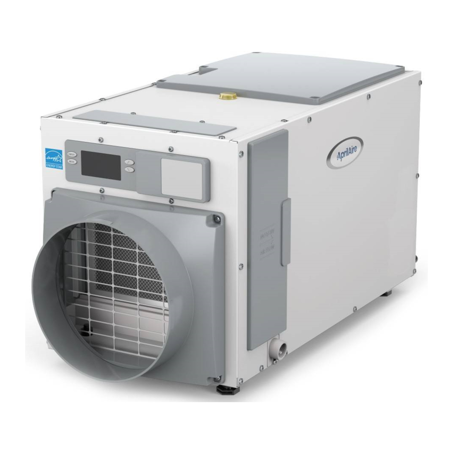
CRAWL SPACE DEHUMIDIFICATION
The AprilAire Dehumidifier controls the humidity level in your crawl space A powerful blower inside the dehumidifier draws air into the cabinet where it is filtered before having moisture removed A sealed refrigeration system removes moisture by moving the air through a series of tubes and fins that are kept colder than the dew point of the incoming air The dew point is the temperature at which moisture in the air will condense, much like what occurs on the outside of a cold glass on a hot summer day The condensed moisture drips into the dehumidifier drain pan to a drain tube routed to the nearest floor drain or condensate pump After the moisture is removed, the air moves through a second coil where it is reheated before being sent back into the crawl space. The air leaving the dehumidifier will be warmer and drier than the air entering the dehumidifier.

You can reduce the amount of humidity that enters the home by closing windows, doors and fireplace flues when outdoor humidity is high, and by drying clothes outside Direct exhaust from kitchen vents and bath fans is the best means of controlling humidity due to cooking and showers/baths. The dehumidifier is not designed to prevent window condensation in winter Use ventilation to lower indoor humidity levels in the winter
SPECIFICATIONS
| Model E080CS | Model E100CS | |||
| Unit Weight | 63 lbs | 64 lbs | ||
| Capacity 80°F, 60% RH Conditions | 80 pints per day @ 185 CFM | 100 pints per day @ 280 CFM | ||
| Current Draw 115 VAC, Single Phase, 60 Hz | 48 A operating current | 67 A operating current | ||
| Dehumidifier Inlet Air Conditions | Dehumidification: 50°F–104°F, 40°F dew point minimum Ventilation: 40°F–140°F, 0% RH–99% RH (non-condensing) | |||
| Filter | MERV 8, washable | |||
| Airflow | External Static Pressure ("w.c.) | Airflow (CFM) | External Static Pressure ("w.c.) | Airflow (CFM) |
| 00 | 185 | 00 | 280 | |
| 02 | 135 | 02 | 245 | |
| 04 | 85 | 04 | 210 | |
| Installation not advised | 06 | 175 | ||
 NOTE: Rated capacity and current draw measured at 80°F/60% RH inlet conditions at 00 external static pressure
OPERATING THE DEHUMIDIFIER
- If equipped, use the ON/OFF power switch, located by the power cord, to apply power to the dehumidifier.
![warning]() NOTE: The unit can remain plugged in with an ON/OFF power switch on, unless the unit will not be used for an extended period. Use the ON/OFF button on the user interface to turn the unit off for short durations When the unit is idle (neither the fan nor the compressor running) the unit will use less than 3W of power.
NOTE: The unit can remain plugged in with an ON/OFF power switch on, unless the unit will not be used for an extended period. Use the ON/OFF button on the user interface to turn the unit off for short durations When the unit is idle (neither the fan nor the compressor running) the unit will use less than 3W of power.

- USER INTERFACE
- ON/OFF POWER SWITCH (SELECT MODELS)
- FILTER ACCESS DOOR
- Use the ON/OFF button (see FIGURE 2) on the user interface to turn the dehumidifier ON.

The first press of a button will turn on the display light, so if the display was dark, you might need to press it again. Once ON, the display will show the current dehumidifier setting. - The dehumidifier blower will turn on, SETTING disappears from the display, and AIR SAMPLING appears (see FIGURE 3)

This indicates that the dehumidifier is sampling the air to determine if dehumidification is needed and shows the measured humidity level If the control is already ON, increasing the dryness setting will initiate air sampling. - After sampling the air for 3 minutes, if the dew point is above the setting, the compressor turns on to dehumidify the space DEHUMIDIFYING appears when the compressor is turned on (see FIGURE 4)


ENERGY SAVINGS TIPS
 ENERGY SAVINGS TIP #1:
Adjust the dew point setting to be as low as is comfortable to reduce dehumidifier run time. If it feels clammy or "smells musty," raise the dew point setting. To save energy, turn the dehumidifier to OFF when you open your windows, just as you would with air conditioning.
ENERGY SAVINGS TIP #2:
If vacating your home for an extended period in the summer, set the dew point setting to 3 and set your thermostat as high as you are comfortable setting it to in the cooling mode. This will keep the humidity at a controlled level while minimizing the amount of cooling energy used.
MAINTENANCE
CLEANING THE FILTER
After initial installation, the air filter and drain should be checked and cleaned every 6 months.
- Press the ON/OFF button on the user interface to turn the unit OFF.
- Remove the snap-on filter access door (see FIGURE 1) from the drain side of the dehumidifier by pulling on the handle until it releases. Then remove the filter door.
- Slide the filter out of the dehumidifier.
- Rinse the filter with water to remove dust and collected particles from the filter.
- Shake off excess water from the filter.
- Clean the drain as described in CLEANING THE DRAIN.
- Reinstall the filter. An arrow on the filter frame shows the direction of airflow and it should point into the dehumidifier.
- If the filter does not slide back in, make sure the drain insert has been properly installed. See INSTALLING THE DRAIN.
- Replace the filter access door by inserting the two alignment tabs then snapping the door onto the side panel. Ensure both filter doors are securely installed.
- Press the ON/OFF button to turn the dehumidifier back ON.
The CLEAN FILTER service reminder (see FIGURE 5) will display on the control every 6 months. To clear the service message, press the![]() and
and ![]() buttons simultaneously for 3 seconds.
buttons simultaneously for 3 seconds.

 and
and  buttons simultaneously for 3 seconds.
CLEANING THE DRAIN
- With the filter door on the drain side of the dehumidifier removed, reach in and pull out the drain insert using the finger loop (see FIGURE 6).

![warning]() NOTE: Drain insert must be installed before operating.
NOTE: Drain insert must be installed before operating. - Clean the accessible portion of the drain pan and the drain insert using a mild detergent.
- If the drain has a capped tee or elbow to allow cleaner to be poured directly in the drain, remove the cap and pour approximately one cup of white vinegar into the tube (see FIGURE 7).

- CAP
- CONDENSATE DRAIN LINE
If there is no visible access to the drain line from outside of the dehumidifier, pour approximately one cup of vinegar into the drain pan of the dehumidifier where the drain insert was located.
- Reinstall the drain insert by gently placing the tip into the drain opening and rocking the insert downwards into place (see FIGURE 6) When inserted properly, the top of the drain insert will be at the same height as the filter guide channel.
- If the dehumidifier has clear flexible drain tubing, look for excess buildup in the drain line that might prevent water flow, and replace as needed. Clear, smooth, flexible 3/4" Inside Diameter (ID) drain tubing is available in most hardware stores or Do-It-Yourself (DIY) retail stores.


NOTICE
Running the dehumidifier without the drain insert can lead to condensate leaks.
PREPARING THE UNIT FOR INSTALLATION

Cut the straps securing the compressor shipping support bracket and remove the straps and shipping bracket (see FIGURE 8)

- PLASTIC STRAPS
- SCREWS
- SHIPPING BRACKET
- ON/OFF POWER SWITCH (SELECT MODELS)
- Clip off and remove the plastic straps securing the compressor to the shipping bracket.
- Remove the two screws securing the shipping bracket to the housing. Remove and discard the shipping bracket, and reinstall the two screws in the dehumidifier.
FLOAT SWITCH AND ALERT LIGHT WIRING
Remove the ALERT LIGHT and FLOAT Switch cables from around the duct collar.
Remove the wire access cover. Plug the 2-terminal block connected to the FLOAT Switch cable into the pins labeled FLOAT Switch on the circuit board. Plug the 4-terminal block connected to the cable into the pins labeled + – A B and the remaining 2-terminal block from the cable into the pins labeled ALERT (see FIGURE 9).

REPOSITIONING THE USER INTERFACE FOR THE APPLICATION
Locate the onboard user interface (see FIGURE 10) on the top of the dehumidifier or at the front of the dehumidifier.

- USER INTERFACE DOOR
- USER INTERFACE
- FILTER ACCESS DOOR
If the user interface cannot be seen/accessed in the top orientation It may also be rotated 180 degrees in either orientation. (see FIGURE 11)

MOVING THE CONTROL
- Remove the front user interface door.
- Remove the filter access door and filter.
- Detach the onboard user interface by removing the four (4) screws around the user interface.
![warning]() NOTE: Use one hand to support the bottom of the onboard user interface when removing.
NOTE: Use one hand to support the bottom of the onboard user interface when removing. - Keep the user interface in the unit and relocate to the front access hole.
- Secure the user interface with the same four screws used to attach the user interface to the top of the unit.
- Secure the user interface door to the top of the unit.
INSTALLING THE DUCT COLLARS
- Use the screws in the parts bag to attach the duct collars to the inlet and outlet of the dehumidifier. The outlet collar has a backflow damper.
- The outlet duct collar may be attached to the top or end of the unit Move the outlet cover to the location not being used (see FIGURE 12).


- INLET DUCT COLLAR
- OUTLET COVER
- OUTLET DUCT COLLAR WITH BACKFLOW DAMPER
- Make sure there are no bends in the ductwork coming off the outlet for a minimum of 4" This precaution will ensure that the ductwork will not interfere with the backflow damper function.
INSTALLING THE DEHUMIDIFIER
DEHUMIDIFIER LOCATION
- Electrical service access and drain cleaning will require the removal of the electrical service side panel (see FIGURE 13) Allow sufficient space for service on this side of the unit.


- ELECTRICAL SERVICE AND DRAIN ACCESS THIS SIDE
- FILTER
- 8 FOOT POWER CORD
- The filter can be removed from either side of the dehumidifier. Allow sufficient space for the filter to be removed and reinstalled
- If locating the unit where it is not readily accessible (such as a crawl space, an attic or even a basement for some individuals), consider controls such as the Model 76 Dehumidifier Control, which can be mounted in the living space and wired to the dehumidifier.
- For attic installations, suspending the dehumidifier is recommended to reduce noise transference
- Always install the dehumidifier in or above a condensate pan when locating in or above a finished space.
LEVELING AND RAISING THE DEHUMIDIFIER
The feet can be adjusted to level the unit and accommodate drain fittings and condensate pans as required. Use the top-mounted bubble level to adjust the feet until the bubble is within the outer circle (see FIGURE 14) The unit must be level from front to back and side to side to ensure proper drainage from the dehumidifier.

- BUBBLE LEVEL
- CONNECTS TO 3/4" I.D. DRAIN TUBE
If installing a condensate pump to the side of the unit more elevation than can be provided by the adjustable feet may be needed. Risers (Part #5879) or hanging kits (Part #5822) are available to lift the dehumidifier higher off the floor.
INSTALLING A CONDENSATE PAN UNDER THE DEHUMIDIFIER
Always install the dehumidifier in or above a condensate pan when locating it above a finished space. Adhere to local codes regarding draining of the condensate pan If a condensate pump is needed, make sure it is in the condensate pan as well. Install a float switch in the condensate pan and/or use the overflow wires/terminals on the condensate pump to stop the dehumidifier should overflow occur. See WIRING TO A FLOAT SWITCH.
INSTALLING THE DRAIN
USING HARD PIPE
- Install a 3/4" PVC slip x 3/4" MNPT PVC fitting to the dehumidifier and use 3/4" nominal PVC Schedule 40 pipe to run the condensate line to the nearest floor drain or to an outside location that slopes away from the building.
- Always maintain a constant downward slope in drain piping. Ensure that drain tubing does not interfere with removal of the side panel or filter door.
- Do not use metal fittings and only hand-tighten threaded fittings. PTFE thread seal tape is recommended for threaded connections.
- Install a tee or three-way elbow at the dehumidifier outlet with a small, capped vertical tube (do not cement cap in place) to allow for cleaner to be poured into the drain line (see FIGURE 15).


- CAP
- SMALL SECTION OF DRAIN TUBE
- 3/4" 3-WAY ELBOW OR TEE AND ELBOW
- CONDENSATE DRAIN LINE
- PVC primer and cement is recommended for slip-fit connections (do not cement threaded connections)
USING FLEXIBLE TUBING
- Install the provided 3/4" NPT x 3/4" hose barb fitting and use 3/4" I.D. flexible drain tubing. Hand-tighten the fitting to the dehumidifier. PTFE thread seal tape is recommended for threaded connections
- Always maintain a constant downward slope from the dehumidifier to the nearest floor drain or condensate pump, and do not allow soft tubing to curl up, which may result in air lock.
INSTALLING THE CONDENSATE PUMP
- The AprilAire Model 4856 condensate pump is capable of lifting water up to 22 feet (see FIGURE 16)


- FLOAT SWITCH WIRE
- 3/4" MNPT X 3/4" BARB FITTING (INCLUDED)
- 3/4" CLEAR PVC TUBING (INCLUDED)
- CONDENSATE PUMP (PART #4856)
- 10" DIAMETER INSULATED FLEX DUCT
- The dehumidifier can be elevated (while remaining level) to increase downward slope for proper draining
- Wire the float switch terminals to the normally closed contacts on the condensate pump (see FIGURE 19)


INSTALLING DUCTWORK
Add ductwork to the inlet and outlet of the dehumidifier to ensure dehumidifed air is circulated throughout the crawl space and reduce the noise level of the dehumidifier. Point the inlet and outlet ducts in opposite directions to minimize recirculation of dehumidified air.
- Maximum recommended total duct length is 100 feet
- To avoid pulling in dirt and other particles, do not lay intake duct on the floor of the crawl space.
NOTE: Maximum allowable static pressure is 04" wc for the E080CS and 06" wc for the E100CS
WIRING
No additional wiring is needed unless:
- a separate, remote control such as a dehumidistat is to be used
- a float switch, either integral to a condensate pump or mounted to the condensate pan, is used
Use 18-22 AWG wire for any needed wiring. Access the dehumidifier wiring terminals by pulling off the wiring access cover near the user interface display (see FIGURE 17) Snap the wiring access cover back into place after completing all wiring.

- USER INTERFACE
- WIRING ACCESS COVER
WIRING TO REMOTE CONTROL
The Model 76, when used as a remote control, allows the user to see the humidity sensed by the dehumidifier and adjust the dehumidifier setting from a remote location. This is most often used when the dehumidifier serves a hard-to-reach location such as a crawl space or basement Wire the remote control as shown in FIGURE 18 (see setup).

WIRING TO A FLOAT SWITCH
Use only if the installation includes a float switch or a condensate pump. The dehumidifier leaves the factory with a jumper wire installed in the float switch terminals. Remove the jumper and wire the float switch terminals to the float switch or condensate pump overflow switch as shown in FIGURE 19.
ALERT LIGHT MOUNTING
- Locate the alert light mounting bracket where it will be readily visible
- Run the ALERT LIGHT to the mounting bracket and clip it in the bracket (see FIGURE 20) Use the provided plastic wire staples to secure the wire in place


- AMBER LIGHT MOUNTING BRACKET
- ALERT LIGHT LOCATED WHERE IT CAN BE EASILY SEEN
- PLASTIC WIRE STAPLE
NOTE: The alert light does not need to be installed for the unit to function.
SETTING THE DESIRED HUMIDITY LEVEL
The dehumidifier can be set up to control based on dew point or relative humidity (%RH).
DEW POINT CONTROL
The dehumidifier on-board control will display the dryness setting when not running, and displays the measured humidity when running
The  and
and  buttons allow the dryness setting to be set from 1 to 7. Use the ON/OFF button to turn the dehumidifier ON or OFF.
Set the control at 3 for initial operation This setting and corresponding dew point is recommended for preservation and preventing condensation on floor joists. Allow the dehumidifier to run until it reaches the setting before deciding if you want to change the setting
- If you prefer the air to be more dry, increase the dryness level
- If you prefer the air to be less dry, decrease the dryness level
- See TABLE 1 for dryness settings and corresponding dew point (DP)
EXAMPLE: At a crawl space temperature of 70°F and a dryness level setting of 3 (57°F DP), the dehumidifier will work to achieve a 63% relative humidity level
- The %RH values are +/- 5% and are to be used as a GUIDE ONLY.
- The crawl space temperature is measured at the dehumidifier inlet.
RELATIVE HUMIDITY (%RH) CONTROL
The dehumidifier on-board control will display the relative humidity setting when not running, and displays the measured relative humidity when running
The and buttons allow the humidity level to be set from 40% to 80% relative humidity. Use the ON/OFF button to turn the dehumidifier ON or OFF.
Set the control at 55% RH when first installed. Allow the dehumidifier to run until it reaches the setting before deciding if you want to change the setting.
- If you prefer the air to be more dry, decrease the humidity setting.
- If you prefer the air to be less dry, increase the humidity setting.
When first installed, your dehumidifier has to remove all the moisture that is initially in your home. The home acts like a sponge so the moisture in the materials of your home is at the same level as the air After drying the air, the materials of the home will release moisture back into the air until they are again at the same level. As a result, it is not uncommon for the dehumidifier to operate for an extended period when first installed.
TABLE 1: %/RH (+/-5%) BASED ON DRYNESS SETTING AND CRAWL SPACE TEMPERATURE
| Dryness Setting & Dew Point | Crawl Space Temperature | ||
| 60°F | 65°F | 70°F | |
| 1 – Less, 65°F DP | 84% | ||
| 2 – 61°F DP | 86% | 73% | |
| 3 – Normal, 57°F DP | 88% | 74% | 63% |
| 4 – Normal, 53°F DP | 76% | 64% | 54% |
| 5 – Normal, 49°F DP | 65% | 55% | 46% |
| 6 – 46°F DP | 55% | 47% | 39% |
| 7 – Most Dry, 42°F DP | 47% | 40% | 34% |
INSTALLER SET-UP
Enter the Set-Up menu if:
- a remote control will be used
- you wish to control the dehumidifier by setting the Relative Humidity (%RH) limit (the default control setting is dewpoint level)
- Plug unit in and turn power switch ON (if equipped).
- The onboard control screen should display OFF. If not OFF, press the ON/OFF button to turn the unit OFF.
![]()
![warning]() NOTE: If the display backlight is not on, the first button press (any button) will only turn on the backlight. Press the button a second time to achieve function
NOTE: If the display backlight is not on, the first button press (any button) will only turn on the backlight. Press the button a second time to achieve function - Hold the MODE button on the onboard control for 3 seconds to enter the Installer Set-Up menu
- Press MODE to navigate through the screens to set up the dehumidifier for the installed application. Press the
![]() or
or ![]() button to select items To exit installer set-up, navigate through all options using the MODE button. Navigate through the following screens to set up the dehumidifier for the installed application
button to select items To exit installer set-up, navigate through all options using the MODE button. Navigate through the following screens to set up the dehumidifier for the installed application - After the Installer Set-Up options have been completed, DONE will blink for 3 seconds and the control will return to the OFF screen.
![]()
- Not all system set-up options will be covered in these instructions The default settings are recommended for those options in most applications


SETTING UP REMOTE CONTROL – CRAWL SPACE/SEALED ATTIC
If wiring to a Model 76 for remote control press the ![]() or
or ![]() button to select ENABLED. Then press the MODE button to advance screen.
button to select ENABLED. Then press the MODE button to advance screen.

%RH CONTROL
By default, this control is based on dew point and uses a dryness setting of 1 to 7 (see TABLE 1) If the preferred setting and control method is relative humidity (%RH), press the ![]() or
or ![]() button to select ENABLED.
button to select ENABLED.

STARTING UP THE UNIT AND SEQUENCE OF OPERATION
Ensure unit is plugged in and, if equipped, use ON/OFF power switch near the power cord to apply power to the dehumidifier.
USING THE DEHUMIDIFIER CONTROL ONLY
- Press the ON/OFF button to turn the dehumidifier control ON. The display will show the current dew point or humidity setting, and the blower will turn on to start sampling. The setting will be replaced by the measured humidity and AIR SAMPLING appears on the display.
- Use the
![]() or
or ![]() button to adjust the humidity setting as desired The recommended initial setting is 3 using dew point control or between 55% and 59% RH.
button to adjust the humidity setting as desired The recommended initial setting is 3 using dew point control or between 55% and 59% RH. - After three (3) minutes of sampling, the measured dew point or humidity will be compared to the setting:
- If the dew point or humidity is above the setting, the dehumidifier compressor turns on and AIR SAMPLING will be replaced by DEHUMIDIFYING The compressor remains on until the measured dew point falls below the setting or the measured humidity falls 3% RH below the setting.
- If the measured dew point or the humidity is below the setting, the blowers turn off and the display returns to showing the setting.
- The dehumidifier will sample again every 60 minutes, or at any time if the humidity setting is lowered.
USING A MODEL 76 AS A REMOTE CONTROL
- Press the ON/OFF button to turn the dehumidifier control ON. The display will show REMOTE to indicate that a remote control is to be used to control the dehumidifier.
- At the Model 76, press the ON button; the Model 76 will display the RH measured at the dehumidifier, and the dehumidifier blower will turn on to start sampling the air.
- Use the
![]() or
or ![]() button on the Model 76 to adjust the dryness level as desired The dryness levels range from 1 to 7, with 1 being least dry and 7 being most dry; the recommended initial setting is 3.
button on the Model 76 to adjust the dryness level as desired The dryness levels range from 1 to 7, with 1 being least dry and 7 being most dry; the recommended initial setting is 3. - After three (3) minutes of sampling, the measured humidity will be compared to the setting:
- If the humidity is above the setting, the dehumidifier compressor turns on and ON flashes on the Model 76 display.
- If the measured humidity is below the setting, the dehumidifier blower turns off.
- The dehumidifier will sample again every 60 minutes, or at any time if the dryness level is increased.
HIGH DEW POINT/HIGH HUMIDITY ALERT
When the alert light is installed, if the dehumidifier measures the dew point of the air to be 4°F or more or 6% RH or more above the setting for 72 consecutive hours, the ALERT LIGHT will turn on and the display will show "HI". The dehumidifier will continue to operate as normal when the ALERT LIGHT is on If the dew point falls within 4°F of the setting or relative humidity falls within 6% RH of the setting, the ALERT LIGHT will turn off.
The dehumidifier measures the conditions of the incoming air every five (5) minutes even if the dehumidifier is turned off (using the ON/OFF button) to determine if there is a high dew or humidity condition. Should the dehumidifier be turned off, the alert setting defaults to 57°F or 60% RH.
TROUBLESHOOTING
NOTICE
Troubleshooting and repairs shall be performed by a qualified HVAC service technician, and all safety procedures shall be followed.
Technical support is available Monday through Friday 7:00 am to 5:00 pm CST at 8003346011. Use the guides obelow to identify and correct system faults Contact Technical Support before replacing the unit or any components and for additional troubleshooting.
DIAGNOSTIC CODES
When an error occurs, the Diagnostic Code along with SERVICE REQUIRED will be displayed on the user interface screen.

TABLE 2: DIAGNOSTIC CODES
| Diagnostic Code | Failure Mode | Action | Reset |
| E1 | Internal Humidity or Temperature Sensor Open or Shorted |
| Cycle Power |
| E2 | High Refrigeration Pressure |
| Cycle Power |
| E3 | Model 76 Remote Control Communication Loss |
| Self-Correcting |
| E4 | Insufficient Capacity |
| Cycle Power |
| E5 | High Temperature Thermistor Failure |
| Cycle Power |
 button and MODE button for 3 seconds. The LCD will display:
  or
or  button
TABLE 2: DIAGNOSTIC CODES
| Diagnostic Code | Failure Mode | Action | Reset | ||
| E6 | Low Temperature Thermistor Failure |
| Cycle Power | ||
| E7 | Float Switch Open |
| Self-Correcting | ||
| E8 | Inlet Air Temperature Out of 50°F–104°F Range, or Dew Point Below 40°F |
| Self-Correcting | ||
| HI (E0) | High Dew Point (High Dew Point on Model 76) |
| Self-Correcting | ||
TABLE 3: TROUBLESHOOTING GUIDE
| Symptom | Failure Mode | Action | |||
| Dehumidifier does not turn on/run. | No power to unit. |
| |||
| Dehumidifier blower is running but with little or no airflow. | Pressure drop across dehumidifier is higher than 04" wc for Model E080CS or 06" wc for Model E100CS |
| |||
| Dehumidifier blower is running but compressor is not. | Float Switch open (E7 appears on display) |
| |||
| Unit is defrosting |
| ||||
| Inlet air temperature is outside of the 50°F–104°F range or the dew point is below 40°F and there is a demand for dehumidification. |
| ||||
| Dehumidifier is not draining properly. | Drain line blocked or unit not level |
| |||
| Dehumidifier is producing hot air. | Normal function. |
|
E080CS/E100CS SERVICE PARTS


Register Your AprilAire® Product
Register your product at aprilaire.com/warranty to receive important updates and notifications, and to streamline the process in the unlikely event you file a claim.
SERVICE & SAFETY INSTRUCTIONS
SYMBOLS
 |  |  |
| Symbol ISO 7010-W021 (2011-05) | Symbol ISO 7000-1659 (2004-01) | Symbol ISO 7000-1659 (2004-01) |
 flammable materials | Service indicator: read technical manual | Operator's manual: operating instructions |
SAFETY INSTRUCTIONS
- Sealed Refrigeration System is not field serviceable!
- This appliance contains a mildly flammable A2L refrigerant.
- Do not use means to accelerate the defrosting process or to clean, other than those recommended by the manufacturer.
- The appliance shall be stored (when not in use) in a room without continuously operating ignition sources (for example: open flames, an operating gas appliance or operating electric heater).
- Do not pierce or burn sealed system.
- Be aware that refrigerants may not contain odor.

When connected via air ducts to one or more rooms the appliance shall be directly ducted to the space. Open areas such as false ceilings shall not be used as a return air duct.
SERVICE
Approved auxiliary devices: Only approved auxiliary devices approved by the appliance manufacturer shall be installed in the ductwork.
- Fresh Air Ventilator, Stock # 8190FF
The following checks shall be applied to installations using
FLAMMABLE REFRIGERANTS:
- The ventilation machinery and outlets are operating adequately and are not obstructed
- Marking on the equipment shall be visible and legible. Markings and signs that are illegible shall be corrected
- When opening the ventilated enclosure for repair of electrical components, be sure to check for refrigerant leaks with a certified flammable refrigerant leak detector
Repair Initial safety checks shall include:
- Servicing the electrical system on the unit should be carried out by a qualified and licensed electrician.
- Disconnect power from the unit (unplug) before attempting service or repair.
- The capacitors are discharged: this shall be done in a safe manner to avoid possibility of sparking; that no live electrical components and wiring are exposed in case of a leak.
- There is continuity of earth bonding.
- Sealed electrical components shall be replaced, not repaired.
- Do not apply any permanent inductive or capacitance loads to the circuit without ensuring that this will not exceed the permissible voltage and current permitted for the equipment in use.
- Intrinsically safe components must be replaced if tripped.
- Replace components only with parts specified by the manufacturer. Other parts may result in the ignition of refrigerant in the atmosphere from a leak.
- Prior to beginning work on systems containing FLAMMABLE REFRIGERANTS, safety checks are necessary to ensure that the risk of ignition is minimized.
- Ensure that the area is in the open or that it is adequately ventilated before removal of the dehumidifier panels for servicing or conducting any hot work in the vicinity of the unit. A degree of ventilation shall continue during the period that the work is carried out. The ventilation should safely disperse any released refrigerant and preferably expel it externally into the atmosphere.
- The refrigeration system is considered factory sealed and puncturing the refrigerant tubing in any way is prohibited.
- Repairing the refrigeration system shall not be performed in the field and must be done at the manufacturing facility by trained personnel.
- Check that cabling will not be subject to wear, corrosion, excessive pressure, vibration, sharp edges, or any other adverse environmental effects. The check shall also consider the effects of aging or continual vibration from sources such as compressors or fans.
- If a leak is suspected, all naked flames shall be removed/extinguished.
The following leak detection methods are deemed acceptable for all refrigerant systems:
- Under no circumstances shall potential sources of ignition be used in the searching for or detection of refrigerant leaks. A halide torch (or any other detector using a naked flame) shall not be used.
- Electronic leak detectors may be used to detect refrigerant leaks but must be calibrated correctly for Flammable Refrigerants. (Detection equipment shall be calibrated in a refrigerant-free area. )
- Ensure that the detector is not a potential source of ignition and is suitable for the refrigerant used.
- Leak detection equipment shall be set at a percentage of the Lower Flammability Limit (LFL) of the refrigerant and shall be calibrated to the refrigerant employed, and the appropriate percentage of gas (25% maximum) is confirmed.
- Leak detection fluids are also suitable for use with most refrigerants but the use of detergents containing chlorine shall be avoided as the chlorine may react with the refrigerant and corrode the copper pipework. Examples of leak detection fluids are:
- bubble method,
- fluorescent method agents.
![warning]() NOTE: The use of silicon sealant can inhibit the effectiveness of some types of leak detection equipment.
NOTE: The use of silicon sealant can inhibit the effectiveness of some types of leak detection equipment.
FOR ADDITIONAL ASSISTANCE:
Technical Support is available Monday through Friday (see TROUBLESHOOTING).
ATTENTION INSTALLER:
- Read this manual before installing. Improper installation or maintenance may cause property damage or injury. It is recommended that installation, service, and maintenance be performed by a trained service technician. This product must be installed in compliance with all local, state, and federal codes.
- All safety precautions must be followed.
- Dispose of properly in accordance with federal or local regulations.

- 120 volts may cause serious injury from electric shock. Disconnect electrical power to the dehumidifier before starting installation or servicing. Leave power disconnected until installation/service is completed.
- To reduce the risk of electrical shock, this equipment has a grounding-type (three prong) plug. This plug will fit only into a grounding-type power outlet. If the plug does not fit into the outlet, contact qualified personnel to install the proper outlet. Do not alter this plug in any way.
- To reduce the risk of electrical shock, position the product so that the power cord can be plugged into an electrical outlet without the use of an extension cord.
RISK OF FIRE OR EXPLOSION:
- Flammable refrigerant used. Do not puncture refrigerant tubing.
- Store in well ventilated room without continuously operating flames or other potential ignition sources.
- Auxiliary devices which may be ignition sources shall not be installed in duct work.
- SHARP EDGES MAY CAUSE INJURY FROM CUTS. Use care when cutting plenum openings and handling ductwork. Always wear glasses/goggles and gloves when installing the unit.
- TWO-PERSON LIFT REQUIRED. Dropping may cause personal injury or equipment damage. Handle with care and follow installation instructions.
- This unit is not intended for use by persons (including children) with reduced physical, sensory, or mental capabilities, or lack of experience and knowledge, unless they have been given supervision or instruction concerning use of the unit by a person responsible for their safety.
- Be sure to supervise children to ensure that they do not play with the unit.
- Be sure to replace a damaged supply cord. It must be replaced by a special cord or assembly available from the manufacturer or its service agent.
- Never operate electrical equipment in standing water.
- Do not stick your fingers or other objects through the safety grills.
- Do not sit or stand on the unit, or use the unit as a table or shelf.
- The unit is designed to be installed indoors only.
- Always place in well ventilated area to prevent the accumulation of refrigerant in the case of a refrigerant system leak or failure.
NOTICE
EQUIPMENT DAMAGE MAY OCCUR IF INSTALLATION INSTRUCTIONS ARE NOT FOLLOWED.
- Do not use in pool applications. Pool chemicals can damage the dehumidifier.
- Do not use solvents or cleaners on or near the display and circuit board. Chemicals can damage components.
- Wait 24 hours before running the unit if it was not shipped or stored in the upright position.
- Do not use dehumidification to prevent window condensation in the winter. To address window condensation, use ventilation to lower indoor humidity in the winter.
- Running the dehumidifier without the drain insert can lead to condensate leaks.
 ELECTRICAL INTERFERENCE CAN CAUSE OUTDOOR TEMPERATURE SENSOR INACCURACY.
- Do not run Outdoor Temperature Sensor alongside wires carrying high voltage (120 VAC or higher).
- Do not run Outdoor Temperature Sensor wire lengths greater than 300 feet.
Documents / Resources
References
Download manual
Here you can download full pdf version of manual, it may contain additional safety instructions, warranty information, FCC rules, etc.
Advertisement


Need help?
Do you have a question about the E080CS and is the answer not in the manual?
Questions and answers