Advertisement
Quick Links
Advertisement

Related Manuals for Garmin GCU475


Summary of Contents for Garmin GCU475
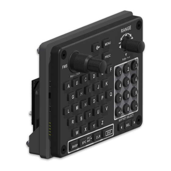
- Page 1 Garmin GCU475 Instructions...
-
Page 2: Important Notes
For Parts list and Mobiflight configuration information: Please refer to the Project resource page at FlightSimDIY.com Important Notes: The part numbers listed on the website are the parts that these PCB’s as well as the 3D print files are designed to use. -
Page 3: Pcb Information
Mobiflight control (MOSFET) or External (Direct) control The GCU475 Control Board is used to connect the Faceplate PCB components to an Arduino mega2560 pro mini (embed) Below you will find the Pin assignments you will need to use when programming your Arduino. - Page 4 Arduino Pin Assignments Arduino Pin Function Arduino Pin Function PROC DECIMAL POINT . NUMBER 0 MENU DIRECT_TO NUMBER 9 RANGE PAN DOWN SPACE RANGE PAN PUSH RANGE PAN ENCODER A NUMBER 1 NUMBER 2 RANGE PAN LEFT NUMBER 3 RANGE PAN UP RANGE PAN ENCODER B FMS OUTER A RANGE PAN RIGHT...
-
Page 5: Parts Needed
Assembly Instructions Parts Needed: (6) M2x13mm screws (4) M2x25mm screws (3) M4x22mm bolts (1) M4x32mm bolt (4) 4mm lock nuts Begin by installing the PCB bracket into the rear of the faceplate. This can be glued onto place (although the PCB mounting screws will hold it in place). - Page 6 Assemble and solder all of the components onto both the faceplate and Mobiflight control board. Place the button onto the key switches. The buttons will sit loosely on to of the switches but will stay in place once the faceplate is in place.
- Page 7 Place the faceplate assembly onto the assembled PCB. Carefully make sure all the buttons slide into the holes in the faceplate Attach the PCB to the faceplate using (6) M2 x 13mm screws. Make sure to leave the holes circled in red empty.
- Page 8 Now we can install the Mobiflight control board with the bracket and (4) M2 x 25mm screws. Install the Arduino card onto the back of the Mobiflight control board.
- Page 9 Attach the dual encoder knobs and the range pan knob. N Install the unit into the cutout in your instrument panel and insert (3) M4 x 22mm and (1) M4 x 32mm bolts. (Note that these are minimum lengths. If your panel is thicker than 1/8 inch then you’ll need longer bolts).
- Page 10 Install the rear panel mount bracket and (4) M4 lock nuts. Complete… Now you can plug the Arduino into your pc via usb and plug you 12v power supply into the backlight power connector. Follow the Mobiflight instructions on the website for installation of the Mobiflight configuration.
Need help?
Do you have a question about the GCU475 and is the answer not in the manual?
Questions and answers