
Related Manuals for Huawei SUN2000 MAP0 Series


Summary of Contents for Huawei SUN2000 MAP0 Series
- Page 1 SUN2000-(5K-12K)-MAP0 Series User Manual Issue Date 2024-05-13 HUAWEI DIGITAL POWER TECHNOLOGIES CO., LTD.
- Page 2 Notice The purchased products, services and features are stipulated by the contract made between Huawei Digital Power Technologies Co., Ltd. and the customer. All or part of the products, services and features described in this document may not be within the purchase scope or the usage scope. Unless otherwise specified in the contract, all statements, information, and recommendations in this document are provided "AS IS"...
-
Page 3: About This Document
● Technical support engineers ● Hardware installation engineers ● Commissioning engineers ● Maintenance engineers Symbol Conventions The symbols that may be found in this document are defined as follows. Issue 01 (2024-05-13) Copyright © Huawei Digital Power Technologies Co., Ltd. - Page 4 Change History Changes between document issues are cumulative. The latest document issue contains all the changes made in earlier issues. Issue 01 (2024-05-13) This issue is the first official release. Issue 01 (2024-05-13) Copyright © Huawei Digital Power Technologies Co., Ltd.
-
Page 5: Table Of Contents
5.2 Preparing Cables................................... 40 5.3 Connecting a PE Cable................................ 44 5.4 Connecting an AC Output Power Cable........................46 5.5 Connecting DC Input Power Cables..........................50 5.6 (Optional) Connecting Battery Cables.......................... 54 Issue 01 (2024-05-13) Copyright © Huawei Digital Power Technologies Co., Ltd. - Page 6 9 Technical Specifications.....................117 9.1 SUN2000-(5K-12K)-MAP0-ZH Technical Specifications..................117 9.2 SUN2000-(5K-12K)-MAP0 Technical Specifications....................123 A Grid Codes..........................131 B Connecting the Inverter on the App................136 C Connecting the EMMA on the App.................140 Issue 01 (2024-05-13) Copyright © Huawei Digital Power Technologies Co., Ltd.
- Page 7 H Digital Power Customer Service..................152 I Certificate Management and Maintenance..............153 I.1 Preconfigured Certificate Risk Disclaimer........................153 I.2 Application Scenarios of Preconfigured Certificates....................154 J Acronyms and Abbreviations.................... 155 Issue 01 (2024-05-13) Copyright © Huawei Digital Power Technologies Co., Ltd.
-
Page 8: Safety Information
● The equipment is operated beyond the conditions specified in this document. Issue 01 (2024-05-13) Copyright © Huawei Digital Power Technologies Co., Ltd. -
Page 9: Personal Safety
D ANGER During operations, use dedicated insulated tools to prevent electric shocks or short circuits. The dielectric withstanding voltage level must comply with local laws, regulations, standards, and specifications. Issue 01 (2024-05-13) Copyright © Huawei Digital Power Technologies Co., Ltd. - Page 10 Professionals: personnel who are familiar with the working principles and structure of the equipment, trained or experienced in equipment operations and are clear of the sources and degree of various potential hazards in equipment installation, operation, maintenance Issue 01 (2024-05-13) Copyright © Huawei Digital Power Technologies Co., Ltd.
-
Page 11: Electrical Safety
WARNING For the equipment that needs to be grounded, install the ground cable first when installing the equipment and remove the ground cable last when removing the equipment. Issue 01 (2024-05-13) Copyright © Huawei Digital Power Technologies Co., Ltd. - Page 12 If the equipment has multiple inputs, disconnect all the inputs before operating the equipment. ● Before maintaining a downstream electrical or power distribution device, turn off the output switch on the power supply equipment. Issue 01 (2024-05-13) Copyright © Huawei Digital Power Technologies Co., Ltd.
- Page 13 ● When routing cables, reserve at least 30 mm clearance between the cables and heat-generating components or areas. This prevents deterioration or damage to the cable insulation layer. Issue 01 (2024-05-13) Copyright © Huawei Digital Power Technologies Co., Ltd.
-
Page 14: Environment Requirements
Otherwise, its performance and safety will be compromised. ● The operating temperature range provided in the equipment's technical specifications refers to the ambient temperatures in equipment's installation environment. Issue 01 (2024-05-13) Copyright © Huawei Digital Power Technologies Co., Ltd. -
Page 15: Mechanical Safety
Do not use tools that have signs of scratches or fail to pass the inspection or whose inspection validity period has expired. Ensure that the tools are secure and not overloaded. Issue 01 (2024-05-13) Copyright © Huawei Digital Power Technologies Co., Ltd. - Page 16 Move a heavy object stably with balanced force at an even and low speed. Put down the object stably and slowly to prevent any collision or drop from scratching the surface of the equipment or damaging the components and cables. Issue 01 (2024-05-13) Copyright © Huawei Digital Power Technologies Co., Ltd.
- Page 17 If a single ladder is used, the recommended angle for the ladder against the floor is 75 degrees, as shown in the following figure. A square can be used to measure the angle. Issue 01 (2024-05-13) Copyright © Huawei Digital Power Technologies Co., Ltd.
- Page 18 Do not drag steel ropes and hoisting tools or bump the hoisted objects against hard objects during hoisting. ● Ensure that the angle between two hoisting ropes is no more than 90 degrees, as shown in the following figure. Issue 01 (2024-05-13) Copyright © Huawei Digital Power Technologies Co., Ltd.
- Page 19 To avoid short circuits or other risks, do not drill holes into buried pipes or cables. ● When drilling holes, protect the equipment from shavings. After drilling, clean up any shavings. Issue 01 (2024-05-13) Copyright © Huawei Digital Power Technologies Co., Ltd.
-
Page 20: Overview
● SUN2000-6K-MAP0 ● SUN2000-8K-MAP0 ● SUN2000-10K-MAP0 ● SUN2000-10K-MAP0-BE ● SUN2000-12K-MAP0 ● SUN2000-5K-MAP0-ZH ● SUN2000-6K-MAP0-ZH ● SUN2000-8K-MAP0-ZH ● SUN2000-10K-MAP0-ZH ● SUN2000-12K-MAP0-ZH Figure 2-1 Model number (using SUN2000-12K-MAP0-ZH as an example) Issue 01 (2024-05-13) Copyright © Huawei Digital Power Technologies Co., Ltd. -
Page 21: Networking Application
The SUN2000 applies to grid-tied PV systems for residential rooftop projects and small-sized utility plants. The system consists of PV strings, grid-tied inverters, AC switches, and power distribution units (PDUs). Issue 01 (2024-05-13) Copyright © Huawei Digital Power Technologies Co., Ltd. - Page 22 (SmartPVMS) (M) Optimizer (N) Battery NO TE For details about the Smart Dongle networking, see the Residential Smart PV Solution Quick Guide (Three-Phase PV+ESS Scenario + Smart Dongle Networking). Issue 01 (2024-05-13) Copyright © Huawei Digital Power Technologies Co., Ltd.
- Page 23 (L) Load SmartPVMS NO TE For details about EMMA networking, see Residential Smart PV Solution Quick Guide (Three-Phase PV+ESS Scenario + EMMA Networking) Residential Smart PV Solution User Manual (EMMA). Issue 01 (2024-05-13) Copyright © Huawei Digital Power Technologies Co., Ltd.
- Page 24 Figure 2-4 Networking with all loads connected to the SmartGuard (dashed boxes indicate optional components) Figure 2-5 Networking with some of loads connected to the SmartGuard (dashed boxes indicate optional components) Issue 01 (2024-05-13) Copyright © Huawei Digital Power Technologies Co., Ltd.
- Page 25 Otherwise, the inverter will be derated, causing the system yield loss. Earthing Systems The SUN2000 supports the TN-S, TN-C, TN-C-S, TT, and IT earthing systems. Figure 2-6 Supported earthing systems Issue 01 (2024-05-13) Copyright © Huawei Digital Power Technologies Co., Ltd.
-
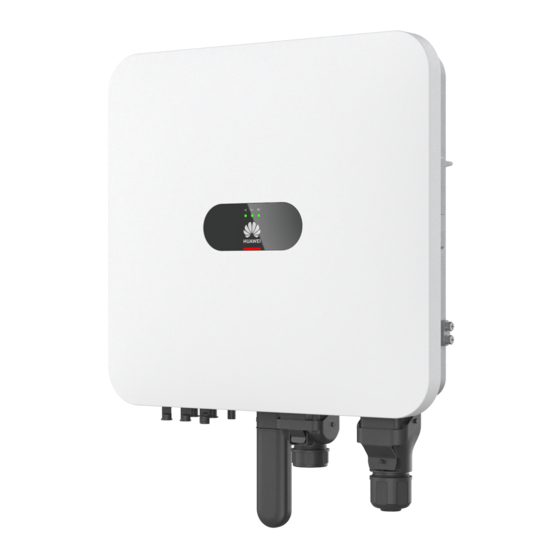
Page 26: Appearance
(3) Mounting bracket (4) Hole for the DC switch padlock (5) DC switch (DC SWITCH) (6) AC output port (AC) (7) Communications port (COM) (8) Smart Dongle port (4G/FE) Issue 01 (2024-05-13) Copyright © Huawei Digital Power Technologies Co., Ltd. - Page 27 Blinking Blinking yellow slowly The inverter is yellow overloaded in off-grid slowly state. Both the DC and AC are off. Issue 01 (2024-05-13) Copyright © Huawei Digital Power Technologies Co., Ltd.
-
Page 28: Working Modes
Steady red Steady red Steady The inverter hardware is indication faulty and needs to be replaced. 2.4 Working Modes The inverter has three working modes: standby, operating, and shutdown. Issue 01 (2024-05-13) Copyright © Huawei Digital Power Technologies Co., Ltd. - Page 29 ● If the PV modules receive no sunlight, the inverter enters shutdown mode after the batteries discharge to the lower SOC threshold. Issue 01 (2024-05-13) Copyright © Huawei Digital Power Technologies Co., Ltd.
-
Page 30: Label Description
Do not touch the warning inverter when it is running because its enclosure is hot. Refer to Reminds operators to documentati refer to the documents delivered with the inverter. Issue 01 (2024-05-13) Copyright © Huawei Digital Power Technologies Co., Ltd. - Page 31 WiFi connect to the connection Huawei inverter WiFi. Product Nameplate The nameplate contains the trademark, product model, important technical specifications, compliance symbols, company name, and place of origin. Issue 01 (2024-05-13) Copyright © Huawei Digital Power Technologies Co., Ltd.
- Page 32 SUN2000-(5K-12K)-MAP0 Series User Manual 2 Overview Figure 2-9 Position of the nameplate (1) Position of the nameplate Issue 01 (2024-05-13) Copyright © Huawei Digital Power Technologies Co., Ltd.
-
Page 33: Storage Requirements
● If inverters have been stored for two years or longer, they must be checked and tested by professionals before being put into use. Issue 01 (2024-05-13) Copyright © Huawei Digital Power Technologies Co., Ltd. -
Page 34: Installation
A salt-affected area refers to a region within 500 m of the coast or prone to sea breeze. Regions prone to sea breeze Issue 01 (2024-05-13) Copyright © Huawei Digital Power Technologies Co., Ltd. -
Page 35: Clearance Requirements
Dimensions of the inverter and mounting holes Figure 4-1 Dimensions of the inverter and mounting brackets ● Reserve enough clearances around the inverter to ensure sufficient space for installation and heat dissipation. Issue 01 (2024-05-13) Copyright © Huawei Digital Power Technologies Co., Ltd. - Page 36 When installing multiple inverters, install them in horizontal mode if sufficient space is available and install them in triangle mode if no sufficient space is available. Stacked installation is not recommended. Figure 4-3 Horizontal installation mode (recommended) Issue 01 (2024-05-13) Copyright © Huawei Digital Power Technologies Co., Ltd.
-
Page 37: Angle Requirements
Install the inverter vertically or at a maximum back tilt of 15 degrees to facilitate heat dissipation. ● Do not install the inverter at forward tilted, excessive backward tilted, side tilted, horizontal, or upside down positions. Issue 01 (2024-05-13) Copyright © Huawei Digital Power Technologies Co., Ltd. -
Page 38: Tools
Hammer drill Flat-head Phillips Hex insulated insulated torque insulated torque torque Drill bit: Ф8 screwdriver screwdriver screwdriver mm, Ф6 mm Hydraulic pliers Insulated Diagonal pliers Wire stripper torque socket wrench Issue 01 (2024-05-13) Copyright © Huawei Digital Power Technologies Co., Ltd. - Page 39 Digital or Cord end terminal tape bubble level crimping tool Heat shrink Heat gun tubing Perso prote ctive equip ment (PPE) Safety shoes Insulated Protective gloves Dust mask gloves Issue 01 (2024-05-13) Copyright © Huawei Digital Power Technologies Co., Ltd.
-
Page 40: Checking Before The Installation
Step 1 To move the inverter, two individuals are required, with one positioned on each side. Carefully lift the inverter out of its packaging case and move it to the designated installation area. Issue 01 (2024-05-13) Copyright © Huawei Digital Power Technologies Co., Ltd. -
Page 41: Installing The Inverter On A Wall
Step 1 Install the mounting brackets. Determine the positions for drilling holes using the marking-off template, level the holes using a level, and mark the positions using a marker. Issue 01 (2024-05-13) Copyright © Huawei Digital Power Technologies Co., Ltd. - Page 42 ● The DC switch padlock needs to be prepared by the customer. Select a padlock based on the lock hole diameter (Ф6 mm) to ensure that the padlock can be installed smoothly. ● An outdoor waterproof padlock is recommended. ● Keep the padlock key properly. Issue 01 (2024-05-13) Copyright © Huawei Digital Power Technologies Co., Ltd.
-
Page 43: Installing The Inverter On A Support
Procedure Step 1 Install the mounting brackets. Determine the positions for drilling holes using the marking-off template, and then mark the positions with a marker. Issue 01 (2024-05-13) Copyright © Huawei Digital Power Technologies Co., Ltd. - Page 44 Step 3 Install the inverter on the mounting brackets. NO TE The M6x16 hexagonal bolts delivered with the inverter are used to secure the mounting bracket and hanging kit in the upper part. Issue 01 (2024-05-13) Copyright © Huawei Digital Power Technologies Co., Ltd.
- Page 45 SUN2000-(5K-12K)-MAP0 Series User Manual 4 Installation Figure 4-13 Installing the inverter ----End Issue 01 (2024-05-13) Copyright © Huawei Digital Power Technologies Co., Ltd.
-
Page 46: Electrical Connections
● Operation personnel must wear PPE when connecting cables. ● Before connecting cables to ports, leave enough slack to reduce the tension on the cables and prevent poor cable connections. Issue 01 (2024-05-13) Copyright © Huawei Digital Power Technologies Co., Ltd. -
Page 47: Preparing Cables
Select cables in accordance with local cable specifications (green-and-yellow cables are only used for protective earthing). 5.2 Preparing Cables Figure 5-1 Inverter cable connections (the components in dashed boxes are optional) Issue 01 (2024-05-13) Copyright © Huawei Digital Power Technologies Co., Ltd. - Page 48 The recommended power meter Purchased from Power meter models are DTSU666-H (250 Huawei A/100 A), DTSU666-HW, YDS60-80, DTSU71, DHSU1079- CT, and YDS60-C24 Supported models: EMMA-A01 Purchased from EMMA and EMMA-A02 Huawei Issue 01 (2024-05-13) Copyright © Huawei Digital Power Technologies Co., Ltd.
- Page 49 Table 5-2 Cable description Name Type Conductor Cross- Outer Sourc Sectional Area Diameter DC input Common 5.5–9 mm Prepar 4–6 mm power cable outdoor PV ed by cable in the industry custo Issue 01 (2024-05-13) Copyright © Huawei Digital Power Technologies Co., Ltd.
- Page 50 ● The minimum cable diameter must meet local standards. ● The factors that affect cable selection include the rated current, cable type, routing mode, ambient temperature, and maximum expected line loss. Issue 01 (2024-05-13) Copyright © Huawei Digital Power Technologies Co., Ltd.
-
Page 51: Connecting A Pe Cable
PE terminal on the AC connector and the ground screws on the enclosure. ● In some countries and regions, the inverter must have additional ground cables. In this case, use cables with the same diameter as the AC output Issue 01 (2024-05-13) Copyright © Huawei Digital Power Technologies Co., Ltd. - Page 52 ● Use a heat gun carefully to avoid heat damage to the equipment. Figure 5-2 Crimping an OT terminal (1) Cable (2) Core wire (3) Heat shrink tubing (4) OT terminal (5) Hydraulic pliers (6) Heat gun Issue 01 (2024-05-13) Copyright © Huawei Digital Power Technologies Co., Ltd.
-
Page 53: Connecting An Ac Output Power Cable
The inverter is installed with an integrated residual current monitoring unit. When the inverter detects that residual current exceeds the permitted value, it disconnects from the power grid quickly. Issue 01 (2024-05-13) Copyright © Huawei Digital Power Technologies Co., Ltd. - Page 54 Tighten the cable conductors to a torque of 2.8–3.2 N·m. Otherwise, the device may fail to run properly or be damaged during operation. Issue 01 (2024-05-13) Copyright © Huawei Digital Power Technologies Co., Ltd.
- Page 55 Step 2 Connect the AC connector together with the AC output power cable to the AC output port. NO TICE Ensure that the AC connector is connected securely. Issue 01 (2024-05-13) Copyright © Huawei Digital Power Technologies Co., Ltd.
- Page 56 Figure 5-5 Securing the AC connector Step 3 Check the route of the AC output power cable. Figure 5-6 Cabling requirements ----End Disconnection Perform the steps in reverse order to disconnect the cable. Issue 01 (2024-05-13) Copyright © Huawei Digital Power Technologies Co., Ltd.
-
Page 57: Connecting Dc Input Power Cables
In this case, an AC or DC short circuit may occur and damage the inverter. The resulting device damage is not covered under any warranty. Issue 01 (2024-05-13) Copyright © Huawei Digital Power Technologies Co., Ltd. - Page 58 Use the positive and negative metal terminals and DC connectors delivered with the inverter. Using incompatible positive and negative metal terminals and DC connectors may result in serious consequences. The resulting device damage is not covered by the product warranty. Issue 01 (2024-05-13) Copyright © Huawei Digital Power Technologies Co., Ltd.
- Page 59 WARNING Before inserting the positive and negative connectors into the positive and negative DC input terminals of the inverter, ensure that the DC SWITCH is set to OFF. Issue 01 (2024-05-13) Copyright © Huawei Digital Power Technologies Co., Ltd.
- Page 60 DC input power cable. Figure 5-10 Connecting DC input power cables ----End Removing DC Connectors WARNING Before removing the positive and negative connectors, ensure that the DC SWITCH is set to OFF. Issue 01 (2024-05-13) Copyright © Huawei Digital Power Technologies Co., Ltd.
-
Page 61: Optional) Connecting Battery Cables
Otherwise, the ingress protection (IP) rating of the inverter will be affected. If a battery connects to the inverter, keep the waterproof covers properly and reinstall them immediately after removing the connectors. Issue 01 (2024-05-13) Copyright © Huawei Digital Power Technologies Co., Ltd. - Page 62 Step 2 Insert the positive and negative connectors into corresponding battery terminals on the inverter. NO TICE After the positive and negative connectors snap into place, pull the battery cables back to ensure that they are connected securely. Issue 01 (2024-05-13) Copyright © Huawei Digital Power Technologies Co., Ltd.
-
Page 63: Connecting Signal Cables
● Use rubber plugs to fill the cable holes where no cables are routed through the waterproof rubber rings, and tighten the locking caps to the recommended torque. Issue 01 (2024-05-13) Copyright © Huawei Digital Power Technologies Co., Ltd. - Page 64 EMMA or al signal– signal, SmartGuar d. When cascaded inverters and the EMMA coexist, they share the 485A1 and 485B1 ports. Shield Shield layer layer groundin groundi Issue 01 (2024-05-13) Copyright © Huawei Digital Power Technologies Co., Ltd.
- Page 65 DIN5 12V_OU 12 V Reserved DIN5 Rapid Used for power port shutdow the rapid output+ shutdown DI signal connectin g to the signal cable of an NS protection device Issue 01 (2024-05-13) Copyright © Huawei Digital Power Technologies Co., Ltd.
- Page 66 ● If a battery is connected to the system, a maximum of three inverters can be cascaded, any of which can be connected to the battery (the inverter connected to the Smart Dongle must be connected to the battery). ● EMMA networking Issue 01 (2024-05-13) Copyright © Huawei Digital Power Technologies Co., Ltd.
- Page 67 ● Ensure that the cables are not twisted. ● If multiple signal cables need to be connected to a single connector, ensure that the outer diameters of the signal cables are the same. Issue 01 (2024-05-13) Copyright © Huawei Digital Power Technologies Co., Ltd.
-
Page 68: Connecting Rs485 Communications Cables (Inverter Cascading)
User Manual 5 Electrical Connections Figure 5-18 Crimping two signal cables 5.7.1 Connecting RS485 Communications Cables (Inverter Cascading) Procedure Step 1 Connect the signal cable to the signal cable terminal. Issue 01 (2024-05-13) Copyright © Huawei Digital Power Technologies Co., Ltd. - Page 69 SUN2000-(5K-12K)-MAP0 Series User Manual 5 Electrical Connections Figure 5-19 Installing the cable Step 2 Connect the signal cable connector to the COM port. Issue 01 (2024-05-13) Copyright © Huawei Digital Power Technologies Co., Ltd.
-
Page 70: Connecting Rs485 Communications Cables (Power Meter)
NO TE The cable connections between the DTSU71 or DHSU1079-CT power meter and the inverter are the same as those between the DTSU666-H (250 A/100 A) and the inverter. Issue 01 (2024-05-13) Copyright © Huawei Digital Power Technologies Co., Ltd. - Page 71 SUN2000-(5K-12K)-MAP0 Series User Manual 5 Electrical Connections Figure 5-21 DTSU666-H (250 A/100 A) three-phase, three-wire cable connection (Smart Dongle networking) Issue 01 (2024-05-13) Copyright © Huawei Digital Power Technologies Co., Ltd.
- Page 72 SUN2000-(5K-12K)-MAP0 Series User Manual 5 Electrical Connections Figure 5-22 YDS60-C24 three-phase, three-wire cable connection (Smart Dongle networking) Issue 01 (2024-05-13) Copyright © Huawei Digital Power Technologies Co., Ltd.
- Page 73 User Manual 5 Electrical Connections Figure 5-23 Three-phase, four-wire connection (Smart Dongle networking) ● The following figures show the cable connections between the inverter and DTSU666-HW and YDS60-80 power meters. Issue 01 (2024-05-13) Copyright © Huawei Digital Power Technologies Co., Ltd.
- Page 74 SUN2000-(5K-12K)-MAP0 Series User Manual 5 Electrical Connections Figure 5-24 Three-phase, three-wire direct connection (Smart Dongle networking) Issue 01 (2024-05-13) Copyright © Huawei Digital Power Technologies Co., Ltd.
- Page 75 Table 5-3 Setting the cable connection mode Parameter Description Set the cable connection mode. 0: n.34 indicates three-phase, four-wire (factory default). 1: n.33 indicates three-phase, three-wire. Issue 01 (2024-05-13) Copyright © Huawei Digital Power Technologies Co., Ltd.
- Page 76 5 Electrical Connections Procedure Step 1 Connect the signal cable to the signal cable terminal. Figure 5-26 Installing the cable Step 2 Connect the signal cable connector to the COM port. Issue 01 (2024-05-13) Copyright © Huawei Digital Power Technologies Co., Ltd.
-
Page 77: Connecting Rs485 Communications Cables (Emma)
5 Electrical Connections Figure 5-27 Securing the signal cable connector ----End 5.7.3 Connecting RS485 Communications Cables (EMMA) Procedure Step 1 Connect the signal cable to the signal cable terminal. Issue 01 (2024-05-13) Copyright © Huawei Digital Power Technologies Co., Ltd. - Page 78 SUN2000-(5K-12K)-MAP0 Series User Manual 5 Electrical Connections Figure 5-28 Installing the cable Step 2 Connect the signal cable connector to the COM port. Issue 01 (2024-05-13) Copyright © Huawei Digital Power Technologies Co., Ltd.
-
Page 79: Connecting Rs485 Communications Cables (Smartguard)
5 Electrical Connections Figure 5-29 Securing the signal cable connector ----End 5.7.4 Connecting RS485 Communications Cables (SmartGuard) Procedure Step 1 Connect the signal cable to the signal cable terminal. Issue 01 (2024-05-13) Copyright © Huawei Digital Power Technologies Co., Ltd. - Page 80 SUN2000-(5K-12K)-MAP0 Series User Manual 5 Electrical Connections Figure 5-30 Installing the cable Step 2 Connect the signal cable connector to the COM port. Issue 01 (2024-05-13) Copyright © Huawei Digital Power Technologies Co., Ltd.
-
Page 81: Connecting The Rapid Shutdown Signal Cable
5.7.5 Connecting the Rapid Shutdown Signal Cable Cable Connection Figure 5-32 Connecting cascaded inverters to the rapid shutdown switch Procedure Step 1 Connect the signal cable to the signal cable connector. Issue 01 (2024-05-13) Copyright © Huawei Digital Power Technologies Co., Ltd. - Page 82 The switch is turned on by default. When the switch is turned off, a rapid shutdown is triggered. Figure 5-33 Installing the cable Step 2 Connect the signal cable connector to the COM port. Issue 01 (2024-05-13) Copyright © Huawei Digital Power Technologies Co., Ltd.
-
Page 83: Connecting The Grid Scheduling Signal Cable
Figure 5-34 Securing the signal cable connector ----End 5.7.6 Connecting the Grid Scheduling Signal Cable Cable Connection The following figure shows the cable connection between the inverter and the ripple control device. Issue 01 (2024-05-13) Copyright © Huawei Digital Power Technologies Co., Ltd. - Page 84 Settings > Power adjustment > Dry contact scheduling on the home screen of the app to disable Dry contact scheduling. Procedure Step 1 Connect the signal cable to the signal cable connector. Issue 01 (2024-05-13) Copyright © Huawei Digital Power Technologies Co., Ltd.
- Page 85 SUN2000-(5K-12K)-MAP0 Series User Manual 5 Electrical Connections Figure 5-36 Installing the cable Step 2 Connect the signal cable connector to the COM port. Issue 01 (2024-05-13) Copyright © Huawei Digital Power Technologies Co., Ltd.
-
Page 86: Connecting Ns Protection Signal Cables
WLAN hotspot of the inverter. Log in to the local commissioning system as an installer, choose Settings > Feature parameters > Dry contact function, and set Dry contact function to NS protection. Issue 01 (2024-05-13) Copyright © Huawei Digital Power Technologies Co., Ltd. - Page 87 Procedure Step 1 Connect signal cables to the signal cable connector (for inverter cascading). Figure 5-39 Installing cables Step 2 Connect the signal cable connector to the COM port. Issue 01 (2024-05-13) Copyright © Huawei Digital Power Technologies Co., Ltd.
-
Page 88: Connecting The Battery Signal Cable
Figure 5-40 Securing the signal cable connector ----End 5.7.8 Connecting the Battery Signal Cable Cable Connection The following figure shows the cable connection between the inverter and the battery. Figure 5-41 Cable connection Issue 01 (2024-05-13) Copyright © Huawei Digital Power Technologies Co., Ltd. -
Page 89: Optional) Installing The Smart Dongle And Anti-Theft Components
For details, see SDongleA-05 Smart Dongle Quick Guide (WLAN-FE). ● If 4G communication is used, install the 4G Smart Dongle (SDongleB-06). For details, SDongleB-06 Smart Dongle Quick Guide (4G). Issue 01 (2024-05-13) Copyright © Huawei Digital Power Technologies Co., Ltd. - Page 90 ● When removing the SIM card, push it inwards to eject it. ● When reinstalling the cover of the Smart Dongle, ensure that the buckles spring back in place with a click sound. Issue 01 (2024-05-13) Copyright © Huawei Digital Power Technologies Co., Ltd.
- Page 91 SUN2000-(5K-12K)-MAP0 Series User Manual 5 Electrical Connections Figure 5-45 Installing the 4G Smart Dongle (SDongleB-06) Figure 5-46 Installing anti-theft components for the Smart Dongle Issue 01 (2024-05-13) Copyright © Huawei Digital Power Technologies Co., Ltd.
-
Page 92: Check Before Power-On
Unused terminals and ports Unused terminals and ports are locked by waterproof glands. Installation environment The installation space is proper, and the installation environment is clean and tidy. Issue 01 (2024-05-13) Copyright © Huawei Digital Power Technologies Co., Ltd. -
Page 93: Power-On And Commissioning
Step 3 Turn on the AC switch between the inverter and the power grid. Step 4 Turn on the DC switch (if any) between the PV strings and the inverter. Step 5 (Optional) Remove the DC switch padlock from the inverter. Issue 01 (2024-05-13) Copyright © Huawei Digital Power Technologies Co., Ltd. - Page 94 Blinking There is a DC red fast environmental alarm, (on for such as High String 0.2s and Input Voltage, String off for Reverse Connection, or 0.2s) Low Insulation Resistance. Issue 01 (2024-05-13) Copyright © Huawei Digital Power Technologies Co., Ltd.
- Page 95 Step 8 (Optional) Observe the Smart Dongle LED indicator to check the status of the Smart Dongle. ● WLAN-FE Smart Dongle Figure 7-1 WLAN-FE Smart Dongle Issue 01 (2024-05-13) Copyright © Huawei Digital Power Technologies Co., Ltd.
- Page 96 The management system is successfully connected. Green Blinking fast (on The inverter is for 0.2s and off communicating with the for 0.2s) management system through the Smart Dongle. ● 4G Smart Dongle Issue 01 (2024-05-13) Copyright © Huawei Digital Power Technologies Co., Ltd.
- Page 97 Check whether the SIM card has been installed or is in good contact. If not, install a SIM card or remove and re- insert the SIM card. Issue 01 (2024-05-13) Copyright © Huawei Digital Power Technologies Co., Ltd.
-
Page 98: Creating A Plant
7.2 Creating a Plant 7.2.1 Downloading the FusionSolar App Method 1: Download and install the app from the app store. ● Huawei mobile phone users: Search for FusionSolar in Huawei AppGallery. ● iPhone users: Search for FusionSolar in the App Store. ●... -
Page 99: Installer Registration
Users who select method 2 can select the download method based on the mobile phone type. ● Huawei mobile phone users: Download from Huawei AppGallery. ● Non-Huawei phone users: Download on a browser. When you select Download via the Browser, if a security warning message is displayed indicating that the app is from an external source, tap ALLOW. - Page 100 If the company requires multiple installer accounts, log in to the FusionSolar app and tap Add user to create another installer account. Figure 7-3 Creating multiple installer accounts for the same company Issue 01 (2024-05-13) Copyright © Huawei Digital Power Technologies Co., Ltd.
-
Page 101: Creating A Plant And An Owner Account
7.2.3 Creating a Plant and an Owner Account Smart Dongle Networking NO TE For details about new plant deployment, see the FusionSolar App Quick Guide or scan the QR code. Issue 01 (2024-05-13) Copyright © Huawei Digital Power Technologies Co., Ltd. - Page 102 If the charger connects to the router through WLAN, you need to log in to the charger to set the WLAN information before deploying the EMMA. 1. Connect to the local commissioning screen of the charger. 2. Tap O&M > Route Management and select WLAN. Issue 01 (2024-05-13) Copyright © Huawei Digital Power Technologies Co., Ltd.
-
Page 103: Commissioning Functions And Features
For details about the commissioning portal when the EMMA networking is used, see C Connecting the EMMA on the App. 7.3.1 Setting Common Parameters Set common parameters based on the devices connected to the plant. Issue 01 (2024-05-13) Copyright © Huawei Digital Power Technologies Co., Ltd. -
Page 104: Optional) Setting The Energy Measurement Mode
This function is used to configure different energy measurement modes for different areas. After power meters are installed, you can configure the measurement modes to implement balanced and unbalanced measurement of energy. Issue 01 (2024-05-13) Copyright © Huawei Digital Power Technologies Co., Ltd. - Page 105 In the Smart Dongle networking scenario, choose Maintenance > Subdevice management > PowerMeter and set Energy Measurement Mode. – In the EMMA networking scenario, choose Settings > Set Installation Parameters and set Energy Measurement Mode. Issue 01 (2024-05-13) Copyright © Huawei Digital Power Technologies Co., Ltd.
-
Page 106: Optional) Three-Phase Imbalance Control
ESS energy is fed to the grid while the PV power can be fed to the grid. The preceding two scenarios are supported concurrently. Issue 01 (2024-05-13) Copyright © Huawei Digital Power Technologies Co., Ltd. - Page 107 Maximum self-consumption or TOU. Procedure Log in to the local commissioning screen. Choose Power adjustment > Active power control and set Three-phase imbalance control to Enable. Issue 01 (2024-05-13) Copyright © Huawei Digital Power Technologies Co., Ltd.
-
Page 108: Optional) Three-Phase Imbalance Control (Emma Networking)
ESS discharge power is fed to the grid while the PV power can be fed to the grid. The preceding two scenarios are supported concurrently. Issue 01 (2024-05-13) Copyright © Huawei Digital Power Technologies Co., Ltd. -
Page 109: Optional) Setting The Physical Layout Of The Smart Pv Optimizers
If a PV module is faulty, you can quickly locate the faulty PV module based on the physical layout to rectify the Issue 01 (2024-05-13) Copyright © Huawei Digital Power Technologies Co., Ltd. -
Page 110: Afci
Function If PV modules or cables are not properly connected or damaged, electric arcs may occur, which may cause fire. Huawei inverters provide unique arc detection in compliance with UL 1699B-2018 to ensure the safety of users' lives and property. - Page 111 To disable this function, log in to the FusionSolar App, enter the Device Commissioning screen, choose Settings > Feature parameters, and disable AFCI. NO TE The AFCI function works only with Huawei optimizers or ordinary PV modules, but does not support third-party optimizers or intelligent PV modules. Clearing Alarms The AFCI function involves the DC arc fault alarm.
-
Page 112: Ips Check (For Italy Cei0-21 Grid Code Only)
Step 2 Tap Starting to start an IPS test. The inverter detects maximum voltage over 10 min (59.S1), maximum overvoltage (59.S2), minimum undervoltage (27.S1), minimum undervoltage (27.S2), maximum overfrequency (81.S1), maximum overfrequency (81.S2), and minimum underfrequency (81.S1), and minimum underfrequency (81.S2). Issue 01 (2024-05-13) Copyright © Huawei Digital Power Technologies Co., Ltd. - Page 113 (0.15 Vn), and the default protection time threshold is 0.2s. (27.S2) Maximum The default overfrequency protection threshold is 50.2 Hz, overfrequency and the default protection time threshold is 0.1s. (81.S1) Issue 01 (2024-05-13) Copyright © Huawei Digital Power Technologies Co., Ltd.
-
Page 114: Drm (Australia As 4777)
Function According to Australia AS 4777.2-2015, inverters need to support the function of demand response modes (DRM), and DRM0 is a mandatory requirement. This function is disabled by default. Issue 01 (2024-05-13) Copyright © Huawei Digital Power Technologies Co., Ltd. - Page 115 Procedure Step 1 Log in to the EMMA on the local app and choose Power adjustment > AS4777 > DRM on the home screen. Step 2 Set DRM to Issue 01 (2024-05-13) Copyright © Huawei Digital Power Technologies Co., Ltd.
-
Page 116: Viewing The Plant Creation Status
Log in to the app, tap Home, and tap Plants. This screen displays the real-time running status and basic information of all plants managed by the user by default. Issue 01 (2024-05-13) Copyright © Huawei Digital Power Technologies Co., Ltd. - Page 117 SUN2000-(5K-12K)-MAP0 Series User Manual 7 Power-On and Commissioning Figure 7-11 Viewing the plant creation status Issue 01 (2024-05-13) Copyright © Huawei Digital Power Technologies Co., Ltd.
-
Page 118: System Maintenance
Table 8-1 Maintenance checklist Check Item Check Method Maintenance Interval System Check periodically whether the heat Once every 6 to 12 cleanliness sinks are blocked or dirty. months Issue 01 (2024-05-13) Copyright © Huawei Digital Power Technologies Co., Ltd. -
Page 119: System Power-Off
6 to 12 months after that Sealing Check whether all terminals and ports Once a year are properly sealed. 8.2 System Power-Off Issue 01 (2024-05-13) Copyright © Huawei Digital Power Technologies Co., Ltd. -
Page 120: Troubleshooting
Step 3 Dispose of the inverter. If the inverter reaches the end of its service life, dispose of it according to local regulations for the disposal of electrical equipment. Issue 01 (2024-05-13) Copyright © Huawei Digital Power Technologies Co., Ltd. -
Page 121: Locating Insulation Resistance Faults
If the insulation resistance is greater than 0.001 MΩ, the fault is not related to short circuit. Check all PV modules in the faulty PV string one by one to locate and rectify the fault. Issue 01 (2024-05-13) Copyright © Huawei Digital Power Technologies Co., Ltd. - Page 122 Maintenance > Inverter ON/OFF, and send a startup command. View alarm information. – If no Low insulation resistance alarm is reported 1 minute after the DC side is powered on, troubleshoot the insulation resistance fault of the PV Issue 01 (2024-05-13) Copyright © Huawei Digital Power Technologies Co., Ltd.
- Page 123 PV strings one by one. Then, go to Step Step 8 Set DC SWITCH to ON. If the inverter status is Shutdown: Command, choose Maintenance > Inverter ON/OFF, and send a startup command. ----End Issue 01 (2024-05-13) Copyright © Huawei Digital Power Technologies Co., Ltd.
-
Page 124: Technical Specifications
SUN2000- SUN2000- 5K-MAP0- 6K-MAP0- 8K-MAP0- 10K- 12K- MAP0-ZH MAP0-ZH Recommen 9000 W 11000 W 14600 W 18000 W 22000 W maximum input DC power Maximum 1100 V input voltage Issue 01 (2024-05-13) Copyright © Huawei Digital Power Technologies Co., Ltd. - Page 125 Maximum number of inputs Number of MPPTs Rated 600 V DC battery voltage Battery 600–980 V DC voltage range Maximum 20 A battery current Battery Li-ion type Issue 01 (2024-05-13) Copyright © Huawei Digital Power Technologies Co., Ltd.
- Page 126 13.3 A/380 16.7 A/380 20.2 A/380 output 9.6 A/400 current 8 A/400 V 12.8 A/400 15.9 A/400 19.1 A/400 7.7 A/415 9.2 A/415 12.2 A/415 15.3 A/415 18.5 A/415 Issue 01 (2024-05-13) Copyright © Huawei Digital Power Technologies Co., Ltd.
- Page 127 150% load (three-phase): 5 minutes 150% load (three- 150% load (single-phase): 5 minutes phase): 1 minute 200% load (three-phase): 10 seconds 150% load (single- phase): 5 minutes 200% load (three- phase): 10 seconds Issue 01 (2024-05-13) Copyright © Huawei Digital Power Technologies Co., Ltd.
- Page 128 (RCMU) Display and Communication Item SUN2000- SUN2000- SUN2000- SUN2000- SUN2000- 5K-MAP0- 6K-MAP0- 8K-MAP0- 10K- 12K- MAP0-ZH MAP0-ZH Display LED indicators; WLAN+app WLAN-FE Supported Dongle 4G Smart Supported Dongle Issue 01 (2024-05-13) Copyright © Huawei Digital Power Technologies Co., Ltd.
- Page 129 –25°C to +60°C temperatur Relative 0–100% RH humidity Cooling Natural cooling mode Maximum 4000 m (derated when the altitude is greater than 2000 m) operating altitude Storage –40°C to +70°C temperatur Issue 01 (2024-05-13) Copyright © Huawei Digital Power Technologies Co., Ltd.
-
Page 130: Sun2000-(5K-12K)-Map0 Technical Specifications
MAP0 MAP0- MAP0 Maximu 98.40% 98.60% 98.60% 98.60% 98.60% 98.60% efficiency European 97.50% 97.70% 98.00% 98.10% 98.10% 98.20% efficiency Note a: The efficiency test condition is three-phase three-wire mode. Issue 01 (2024-05-13) Copyright © Huawei Digital Power Technologies Co., Ltd. - Page 131 MPPT Minimu 160 V startup voltage MPPT 160–1000 V voltage range Full-load 400–850 V MPPT voltage range Rated 600 V input voltage Maximu number of inputs Number of MPPTs Issue 01 (2024-05-13) Copyright © Huawei Digital Power Technologies Co., Ltd.
- Page 132 6600 W 8800 W 11000 W 10000 W 13200 W m active power (cosφ = Rated 220 V/380 V, 3W/N+PE output 230 V/400 V, 3W/N+PE voltage 240 V/415 V, 3W/N+PE Issue 01 (2024-05-13) Copyright © Huawei Digital Power Technologies Co., Ltd.
- Page 133 Power 0.8 leading ... 0.8 lagging factor Output < 0.25% of the rated output compone nt (DCI) Maximu < 3% (rated conditions) m total harmonic distortion THDi) Issue 01 (2024-05-13) Copyright © Huawei Digital Power Technologies Co., Ltd.
- Page 134 Protection Item SUN200 SUN200 SUN200 SUN200 SUN200 SUN200 0-5K- 0-6K- 0-8K- 0-10K- 0-10K- 0-12K- MAP0 MAP0 MAP0 MAP0 MAP0- MAP0- Overvolt PV II/AC III category Input DC Supported switch Issue 01 (2024-05-13) Copyright © Huawei Digital Power Technologies Co., Ltd.
- Page 135 (RCMU) Display and Communication Item SUN200 SUN200 SUN200 SUN200 SUN200 SUN200 0-5K- 0-6K- 0-8K- 0-10K- 0-10K- 0-12K- MAP0 MAP0 MAP0 MAP0 MAP0- MAP0 Display LED indicators; WLAN+app Issue 01 (2024-05-13) Copyright © Huawei Digital Power Technologies Co., Ltd.
- Page 136 490 mm x 460 mm x 130 mm ns (W x H x D) ≤ 21 kg weight Noise ≤ 29 dB (typical working condition) Operatin –25°C to +60°C temperat Relative 0–100% RH humidity Issue 01 (2024-05-13) Copyright © Huawei Digital Power Technologies Co., Ltd.
- Page 137 IP66 Topology Transformerless Wireless Communication Parameters Item Inverter Built-in WiFi Frequency 2400–2483.5 MHz Protocols and standards WLAN 802.11b/g/n Bandwidth ≤ 20 MHz Maximum transmit power ≤ 20 dBm EIRP Issue 01 (2024-05-13) Copyright © Huawei Digital Power Technologies Co., Ltd.
-
Page 138: A Grid Codes
(50 Hz) Island- Grid code Support Support Support Support Support Grid for off-grid operation Table A-2 SUN2000-10K-MAP0-BE grid code Grid Code Description SUN2000-10K- MAP0-BE C10/11 Belgium power grid Supported Issue 01 (2024-05-13) Copyright © Huawei Digital Power Technologies Co., Ltd. - Page 139 Suppo Suppo Suppo power grid rted rted rted rted rted standard IEC61727-60H IEC 61727 Suppo Suppo Suppo Suppo Suppo low-voltage rted rted rted rted rted grid- connection (60 Hz) Issue 01 (2024-05-13) Copyright © Huawei Digital Power Technologies Co., Ltd.
- Page 140 Hong Kong Suppo Suppo Suppo Suppo Suppo low-voltage rted rted rted rted rted power grid EN50549-SE Sweden Suppo Suppo Suppo Suppo Suppo power grid rted rted rted rted rted Issue 01 (2024-05-13) Copyright © Huawei Digital Power Technologies Co., Ltd.
- Page 141 Israel power Suppo Suppo Suppo Suppo Suppo grid rted rted rted rted rted FINLAND- Finland Suppo Suppo Suppo Suppo Suppo EN50549- power grid rted rted rted rted rted LV230 Issue 01 (2024-05-13) Copyright © Huawei Digital Power Technologies Co., Ltd.
- Page 142 Custom (50 Reserved Suppo Suppo Suppo Suppo Suppo rted rted rted rted rted Custom (60 Reserved Suppo Suppo Suppo Suppo Suppo rted rted rted rted rted Issue 01 (2024-05-13) Copyright © Huawei Digital Power Technologies Co., Ltd.
- Page 143 B Connecting the Inverter on the App Connecting the Inverter on the App Step 1 Access the Commission Device screen. Figure B-1 Method 1: before login (not connected to the Internet) Issue 01 (2024-05-13) Copyright © Huawei Digital Power Technologies Co., Ltd.
- Page 144 B Connecting the Inverter on the App Figure B-2 Method 2: after login (connected to the Internet) Step 2 Connect to the inverter WLAN, log in as Installer, and access the device commissioning screen. Issue 01 (2024-05-13) Copyright © Huawei Digital Power Technologies Co., Ltd.
- Page 145 If the access fails in WEP mode, log in to the router and change the encryption mode of the router to WPA2 or WPA/WPA2. Issue 01 (2024-05-13) Copyright © Huawei Digital Power Technologies Co., Ltd.
-
Page 146: B Connecting The Inverter On The App
WLAN, tap CONNECT. Otherwise, you cannot log in to the system. The actual UI and messages may vary with mobile phones. ----End Issue 01 (2024-05-13) Copyright © Huawei Digital Power Technologies Co., Ltd. - Page 147 C Connecting the EMMA on the App Connecting the EMMA on the App Step 1 Access the Commission Device screen. Figure C-1 Method 1: before login (not connected to the Internet) Issue 01 (2024-05-13) Copyright © Huawei Digital Power Technologies Co., Ltd.
- Page 148 C Connecting the EMMA on the App Figure C-2 Method 2: after login (connected to the Internet) Step 2 Connect to the EMMA WLAN, log in as Installer, and access the device commissioning screen. Issue 01 (2024-05-13) Copyright © Huawei Digital Power Technologies Co., Ltd.
- Page 149 If the access fails in WEP mode, log in to the router and change the encryption mode of the router to WPA2 or WPA/WPA2. Issue 01 (2024-05-13) Copyright © Huawei Digital Power Technologies Co., Ltd.
-
Page 150: C Connecting The Emma On The App
WLAN, tap CONNECT. Otherwise, you cannot log in to the system. The actual UI and messages may vary with mobile phones. ----End Issue 01 (2024-05-13) Copyright © Huawei Digital Power Technologies Co., Ltd. -
Page 151: D Resetting A Password
Step 6 Set router and management system parameters to implement remote management. ----End NO TICE You are advised to reset the password in the morning or at night when the solar irradiance is low. Issue 01 (2024-05-13) Copyright © Huawei Digital Power Technologies Co., Ltd. -
Page 152: E Rapid Shutdown
10 ● Method 4: If AFCI is enabled, the inverter automatically performs arc fault detection and triggers a rapid shutdown when AFCI lock protection is implemented. Issue 01 (2024-05-13) Copyright © Huawei Digital Power Technologies Co., Ltd. -
Page 153: F Baud Rate Negotiation
QR code to connect to the EMMA. 2. Access the Communication settings screen, choose RS485 Settings > Baud Rate Negotiation, and tap 9600 and Negotiate a higher rate. Issue 01 (2024-05-13) Copyright © Huawei Digital Power Technologies Co., Ltd. - Page 154 QR code to connect to the networking inverter. 2. Access the Communication configuration screen, choose RS485 > Baud Rate Negotiation > RS485_1 > Baud Rate Negotiation, and tap 9600 and Negotiate a higher rate. Issue 01 (2024-05-13) Copyright © Huawei Digital Power Technologies Co., Ltd.
- Page 155 > Baud Rate Negotiation > RS485_2 > Baud Rate Negotiation, and tap 9600 and Negotiate a higher rate. Troubleshooting If manual baud rate negotiation fails, refer to the following troubleshooting measures. Issue 01 (2024-05-13) Copyright © Huawei Digital Power Technologies Co., Ltd.
- Page 156 In this case, you only need to tap 9600. 6. If the fault persists, contact your vendor. Issue 01 (2024-05-13) Copyright © Huawei Digital Power Technologies Co., Ltd.
-
Page 157: G Contact Information
To ensure faster and better services, we kindly request your assistance in providing the following information: ● Model ● Serial number (SN) ● Software version ● Alarm ID or name ● Brief description of the fault symptom Issue 01 (2024-05-13) Copyright © Huawei Digital Power Technologies Co., Ltd. - Page 158 SUN2000-(5K-12K)-MAP0 Series User Manual G Contact Information NO TE EU Representative Information: Huawei Technologies Hungary Kft. Add.: HU-1133 Budapest, Váci út 116-118., 1. Building, 6. floor. Email: hungary.reception@huawei.com Issue 01 (2024-05-13) Copyright © Huawei Digital Power Technologies Co., Ltd.
-
Page 159: H Digital Power Customer Service
SUN2000-(5K-12K)-MAP0 Series User Manual H Digital Power Customer Service Digital Power Customer Service https://digitalpower.huawei.com/robotchat/ Issue 01 (2024-05-13) Copyright © Huawei Digital Power Technologies Co., Ltd. -
Page 160: I Certificate Management And Maintenance
Preconfigured Huawei-issued certificates are used only in the deployment phase, for establishing initial security channels between devices and the customer's network. Huawei does not promise or guarantee the security of preconfigured certificates. The customer shall bear consequences of all security risks and security incidents arising from using preconfigured Huawei-issued certificates as service certificates. -
Page 161: Application Scenarios Of Preconfigured Certificates
Modbus TCP. corresponding security maintenance manual. Certificates for communication between the Company's products can be replaced. Issue 01 (2024-05-13) Copyright © Huawei Digital Power Technologies Co., Ltd. -
Page 162: J Acronyms And Abbreviations
Acronyms and Abbreviations AFCI Arc-fault Circuit Interrupter Light Emitting Diode Maximum Power Point MPPT Maximum Power Point Tracking Protective Earthing Potential Induced Degradation Photovoltaic Relative Humidity State of Charge Issue 01 (2024-05-13) Copyright © Huawei Digital Power Technologies Co., Ltd.
Need help?
Do you have a question about the SUN2000 MAP0 Series and is the answer not in the manual?
Questions and answers