Table of Contents
Advertisement
Quick Links
Advertisement
Table of Contents

Related Manuals for pico Technology P1053


Summary of Contents for pico Technology P1053
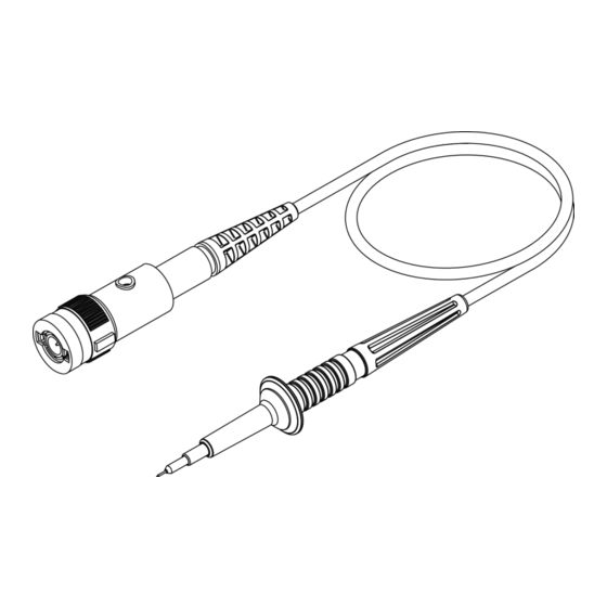
- Page 1 P1053 500 MHz 10:1 oscilloscope probe User's Guide...
-
Page 2: Ec Declaration Of Conformity
(including damages for loss of profits, loss of business, loss of use or data, interruption of business and the like), even if Pico Technology has been advised of the possibility of such damages arising from any defect or error in this manual or product. -
Page 3: Maximum Input Voltage
P1053 500 MHz 10:1 oscilloscope probe User's Guide Safety To prevent possible electrical shock, fire, personal injury, or damage to the product, carefully read this safety information before attempting to install or use the product. In addition, follow all generally accepted safety practices and procedures for working with and near electricity. - Page 4 User's Guide P1053 500 MHz 10:1 oscilloscope probe WARNING To avoid overloading the probe, note that its maximum input voltage rating decreases as the frequency of the applied signal increases. Typical voltage derating P1053 No Measurement Category WARNING To prevent electric shock, take all necessary safety precautions when working on equipment where hazardous live voltages may be present.
-
Page 5: External Connections
The probe contains no user-serviceable parts. Repair, servicing and calibration require specialized test equipment and must only be performed by Pico Technology or an approved service provider. There may be a charge for these services unless covered by the Pico two-year warranty. - Page 6 Spring-loaded tips Ensures secure connection to test points. • Variety of accessories Includes various probing attachments for adaptability. Overall, the P1053 probe from Pico Technology offers a compelling combination of performance, size, and versatility for oscilloscope users working on demanding applications. DO381-1...
-
Page 7: Electrical Specifications
P1053 500 MHz 10:1 oscilloscope probe User's Guide Specifications This User's Guide supersedes all previously published material. Specifications that are not marked as guaranteed are published as general information to the user. The instrument should have warmed up for at least 20 minutes and the environmental conditions must not exceed the specified limits of the probe. -
Page 8: Frequency Compensation
User's Guide P1053 500 MHz 10:1 oscilloscope probe Frequency compensation Before taking any measurements using the probe, first check its compensation and adjust it to match the channel inputs. Connect the probe to a 2 V pk-pk, 1 kHz square wave source. Most PicoScope oscilloscopes have a signal generator output marked GEN or AWG, or a probe CAL pin, which you can configure to generate such a signal. -
Page 9: Probe Accessories
P1053 500 MHz 10:1 oscilloscope probe User's Guide Probe accessories connector Set coding rings Trimmer Ground lead 4x2 colors tool 17 cm Spring tips 0.5 mm Rigid ground spring 3.5 mm Rigid tips 0.4 mm Protection cap 3.5 mm Sprung hook BNC Adaptor 3.5 mm... - Page 10 User's Guide P1053 500 MHz 10:1 oscilloscope probe Probe accessories You can buy a range of kits containing accessories and spare parts for the P1053 probe. Contents of the standard product packs and optional kits are listed below. Probe 500 MHz...
- Page 11 P1053 500 MHz 10:1 oscilloscope probe User's Guide Maintenance Changing the probe tip To change the probe tip use pliers to grip and pull it carefully straight out of its contact socket, along the axis of the probe. Do not grip the white plastic insulator or the housing with pliers, because the tip could be squeezed and made impossible to remove and the probe could be damaged.
- Page 12 +49 (0) 5131 907 62 90 info.de@picotech.com Information in this publication supersedes that in all previously published material. Pico Technology is a registered trade mark of Pico Technology Ltd. Copyright © 2024 Pico Technology Ltd. All rights reserved.
Need help?
Do you have a question about the P1053 and is the answer not in the manual?
Questions and answers