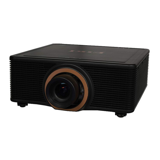
Eiki EK-623U Service Manual
Hide thumbs
Also See for EK-623U:
- Owner's manual (83 pages) ,
- Quick start manual (2 pages) ,
- Owner's manual (83 pages)

Related Manuals for Eiki EK-623U


Summary of Contents for Eiki EK-623U
- Page 1 SERVICE MANUAL EK-623U/EK-623U(W) Date Revise Version Description 2018.12.03 V1.0 Initial Issue Copyright December 2018 All Rights Reserved (C) 2018 EIKI Industrial Inc,...
- Page 2 Preface This manual is applied to EK-623U/EK-6231U projection system.The manual gives you a brief description of basic technical information to help in service and maintain the product. Your customers will appreciate the quick response time when you immediately identify problems that occur with our products.We expect your customers will appreciate the service that you offer them.
- Page 3 EK-623U and EK-623U(W) Comparison List Parts EK-623U EK-623U(W) Main Board 80.7BA01G001 80.7BA01G021 LD Driver 75.7A7P2G001 75.7A7P3G001 Light Engine 70.7BA10GR01 70.7BA19GR01 Color Wheel 70.7AJ36GR01 70.7DK16GR01 Combiner 70.7BA16GR01 70.7BA20GR01 Top Cover 75.74K07G011 75.7BA11G001 Left Cover 75.74K05G001 75.7DK01G001 Right Cover 51.70M04G001 51.70M04G011 Front Cover 75.70M05G041...
-
Page 4: Table Of Contents
Disassemble Combiner 2-16 Disassemble Driver Board 2-21 Disassemble Power Supply 2-23 Disassemble Right Cover 2-24 Disassemble Bottom Cover Module 2-25 Repair action 2-26 Chapter 3 Troubleshooting LED Lighting Message Main Procedure No Power Troubleshooting Power Troubleshooting Image Troubleshooting Remote Troubleshooting EK-623U/EK-6231U... - Page 5 Network Troubleshooting Chapter 4 Test & Inspection Test Equipment Needed Service Mode Factory Reset Calibration Adjustment Chapter 5 Firmware Upgrade Scalar/MCU/DDP/MST9813/LPC1113 FW upgrade Re-write Serial Number Appendix A Exploded Image Appendix B Error Log Appendix C Wiring Diagram EK-623U/EK-6231U...
-
Page 6: Chapter 1 Introduction
0.75 ~ 0.95 AH-A22020 (A01) 0.95 ~ 1.22 AH-A22050 (A02) 1.22 ~ 1.53 AH-A22040 (A05) 1.22 ~ 1.53 AH-A21010 (A03) 1.52 ~ 2.92 AH-A23010 (A13) 2.90 ~ 5.50 AH-A25010 (A13) 0.361(120”) Lens Shift Horizontal: +/- 15%,Vertical: +/-50% Uniformity Typical 90%,Minimum85%(JBMA) EK-623U/EK-6231U... - Page 7 Timing for frame sequential 3D 1024x768 @ 120Hz 1280x720 @ 120Hz 3D Function ii. Timing for HDMI 1.4a mandatory 3D B. Support 3D display types DLP Link™ 3D VESA 3D 0~2500 ft: 5~40°C Operating 2500~5000 ft: 5~35°C Temperature 5000~10000 ft: 5~30°C EK-623U/EK-6231U...
-
Page 8: Compatible Mode
EK-623U/EK-6231U - 19 -... - Page 9 - 20 - EK-623U/EK-6231U...
- Page 10 EK-623U/EK-6231U - 22 -...
-
Page 11: Lan Function
Down Digital 5152 Enter Digital 5156 Exit Digital 5155 Firmware Version Serial 5056 Freeze Off Digital 5106 Freeze On Digital 5105 IP Address Serial 5040 Lamp Hours Serial 5004 Lamp Mode Serial 5003 Left Digital 5153 Location Serial 5052 EK-623U/EK-6231U... - Page 12 Source Select 6 Digital 5075 Status Message Serial 5001 Subnet Mask Serial 5041 Digital 5151 User New Password Serial 5061 User Password Disable Digital 5213 User Password Enable Digital 5212 Warm Up Digital 5160 Warm Up Progress Analog 5010 EK-623U/EK-6231U...
- Page 13 Mute status query AVMT? Error status query ERST? Lamp number/lighting hour query LAMP? Input toggling list query INST? Projector name query NAME? Manufacture name information query INF1? Production name information query INF2? Other information query INFO? Class information query CLSS? EK-623U/EK-6231U...
-
Page 14: Disassembly Process
4. Hex Sleeves 5 mm 5. Tweezers 6. Knife 7. Projector * Before you start: - This process is protective level II. Operators should wear electrostatic chains. - When disassemble Engine module , please notice that it require specific environmental conditions (clean room). EK-623U/EK-6231U... -
Page 15: Disassemble Projector Lens
Projector lens Note: - Please hold lens module in the right way. - Be careful not to dirty the glass of the lens module. - Be careful not to touch the motor of the lens module Right Wrong EK-623U/EK-6231U... -
Page 16: Disassemble Top Cover
2-3 Disassemble Top Cover 1. Loosen 4 black screws (as red circle). 2. Loosen 8 screws (as green circle). 3.Take the top cover module out. 4.Remove the 2 sponges from the top cover. Top cover EK-623U/EK-6231U... -
Page 17: Disassemble Main Board Module
Module 1. Take out the top IR sensor board from the hook. 2. Loosen 18 screws to disassemble top shielding (as green circle). 3. Loosen 2 screws to disassemble LED board (as red circle). LED board IR sensor board EK-623U/EK-6231U... - Page 18 4. Remove 3 screws and 10 hex screws (as red circle). 5.Remove 10 screws to disassemble main board module (as red circle). 6.On the main board, disconnect the 16 connectors, indicated by the labels in the image below. EK-623U/EK-6231U...
- Page 19 Composed of white, black, and red wires, a NEOR red connector (3 pin) J21 F/W SEN- Composed of white, black, and red wires, a red connector (3 pin) Composed of a white connector, and a black J48 DRIVER BD wire tube (30 pin) EK-623U/EK-6231U...
- Page 20 (4 pin) Composed of black, white, and red J14 RSE32 wires, a white connector, and a red wire tube (4 pin) 7.Remove 2 screws and 1 connector on the bottom side to disassemble IO board (as red circle). IO board EK-623U/EK-6231U...
- Page 21 8. Remove 2 hex screws to take out RS232 connector. RS232 connector 9.Loosen 4 screws to disassemble main board bottom shielding (as green circle). EK-623U/EK-6231U...
-
Page 22: Disassemble
2-5 Disassemble Front Cover 1.Remove 2pcs of 3M tape and remove 8 screws to disassemble front cover (as red circle). 2. Take out the front IR sensor board (as red rectangle). IR sensor board Front Cover EK-623U/EK-6231U... -
Page 23: Disassemble Io Cover
3.Remove 4 screws to disassemble front shielding (as blue circle). 2-6 Disassemble IO Cover 1.Loosen 4 screws on the rear cover (as red circle). EK-623U/EK-6231U 2-10... - Page 24 2.Loosen 2 screws (as green circle). 3.Loosen 6 screws to separate IO cover and keypad board (as red circle). IO Cover Keypad board Rubber EK-623U/EK-6231U 2-11...
-
Page 25: Disassemble Left Cover
2-7 Disassemble Left Cover 1.Remove 5 screws to disassemble left cover (as blue circle). 2.Remove 2 screws to take out the interlock switch (as red circle). Left Cover EK-623U/EK-6231U 2-12... -
Page 26: Disassemble Engine Module
2-8 Disassemble Engine Module 1.Loosen 4 screws to disassemble fan4 & fan5 module (as green circle). Fan 5 Fan 4 2.Separate the affected fan holder and fan. Fan4&Fan5 EK-623U/EK-6231U 2-13... - Page 27 3.Unplug 2 connectors (as green circle). 4.Remove 9 screws and unplug the connector for the thermal switch cable (as green circle) to disassemble the engine module (as red circle). 5.Loosen 1 screws to disassemble the thermal switch (as red circle). Thermal Switch EK-623U/EK-6231U 2-14...
-
Page 28: Disassemble Engine Board
White connector, and a black wire tube (30 pin) Composed of two white wires, a white con- nector, and a black wire tube (2 pin) Composed of black, yellow, and red wires, LIGHT SEN- a white connector, and a black wire tube (6 pin) EK-623U/EK-6231U 2-15... -
Page 29: Disassemble Combiner
Composed of yellow, white, red, and blue H-motor wires, a white connector, and a black wire tube (4 pin) 2-10 Disassemble Combiner 1.Remove the write slicone and rubber, then loosen 5 screws to disassemble the filter sealing cover (as green circle). EK-623U/EK-6231U 2-16... - Page 30 2.Loosen 3 screws to disassemble filter wheel module (as red circle). Filter wheel module 3. Remove the 4 M3 screws with a Phillips #1 screwdriver securing the combiner module Combiner Module EK-623U/EK-6231U 2-17...
- Page 31 4.Remove the mylar which is phased on the heatsink. 5.Remove 4 screws securing the DMD heat sink (as green circle). 6 .Loosen 3 screws to disassemble DMD board (as red circle). EK-623U/EK-6231U 2-18...
- Page 32 Note: When replacing the DMD module ensure that the new thermal pad is applied evenly. DMD Chip 8. Release the bracket and mylar from the DMD board. DMD board 9. Remove the sealing sponge from the light engine. Light engine mod- EK-623U/EK-6231U 2-19...
- Page 33 11. Unscrew 2 screws M3*6 (as green circles) to disassemble optical engine board module. Motor Optical engine board 12. Unscrew 2 screws M2.6*4 (as red circles) and unplug 1 connector to disassemble optical engine board. EK-623U/EK-6231U 2-20...
-
Page 34: Disassemble Driver Board
1. Cut off the cable tie and remove the mylar (as green square). 2. Remove 3 screws securing the power supply shielding (as red circle). 3. Lift up the power supply shielding and disconnected the laser driver to power supply harnesses (as green square). EK-623U/EK-6231U 2-21... - Page 35 4.Remove 6 screws securing the laser driver board (as red circle). 5.On the laser driver board, disconnected the To mian board 4 harnesses. To power supply Driver board EK-623U/EK-6231U 2-22...
-
Page 36: Disassemble Power Supply
2-12 Disassemble Power Supply To main board To interlock switch 1.Unplug the four connectors (as arrow). To AC inlet To thermal Switch Interlock switch 2.Remove the 7 ground screws to disassemble the power supply (as green circle). Power supply EK-623U/EK-6231U 2-23... -
Page 37: Disassemble Right Cover
2-13 Disassemble Right Cover Module 1.Loosen 4 screws to disassemble right cover (as red circle). 2.Loosen 4 screws to disassemble fan2 & fan1 (as green circle). Fan 1 Fan 2 Fan1&Fan2 Right Cover EK-623U/EK-6231U 2-24... -
Page 38: Disassemble Bottom Cover Module
2.Loosen 3 nuts to disassemble adjusting foot (as green circle). 3. Remove 1 ground screw to disassemble the AC inlet (as yellow circle). Foot Fan3 4.Loosen 17 screws to disassemble the bottom cover (as red circle). AC inlet Bottom Cover EK-623U/EK-6231U 2-25... -
Page 39: Repair Action
2-15 Repair Action Repair action Change parts Software Main Optical Filter Combiner DMD Board Firmware Board Engine Wheel Firmware Version Update Filter Wheel Index Phosphor Wheel Index Factory Reset LS Calibration Lens Calibration Focus Adjustment Adjustment Re-write Serial Number EK-623U/EK-6231U 2-26... -
Page 40: Chapter 3 Troubleshooting
AV mute is on (Image is Steady Steady Steady black) Projector communication Steady Flashing Steady Firmware upgrade Flashing Flashing Laser diode time has Steady Flashing expired Unit loses over 60% initial luminance Error (Over temperature) Steady Error (Fan failure) Flashing EK-623U/EK-6231U... -
Page 41: Main Procedure
Refer to power Do the lasers ignite? troubleshooting Refer to image Is the image quality good? troubleshooting Refer to IR remote Is the IR remote keypad troubleshooting working? Refer to network Is the network connection troubleshooting functioning? No fault found EK-623U/EK-6231U... -
Page 42: No Power Troubleshooting
Ensure the interlock switch is in Is the interlock switch closed? the closed position Replace the power supply Measure the voltage of J7, pins 1,12~14 is the output 5V? Replace the main board and the keypad board. No fault found EK-623U/EK-6231U... -
Page 43: Power Troubleshooting
3-4-1 Power Troubleshooting EK-623U/EK-6231U... - Page 44 3-4-2 Power Troubleshooting EK-623U/EK-6231U...
-
Page 45: Image Troubleshooting
3-5-1 Image Troubleshooting EK-623U/EK-6231U... - Page 46 3-5-2 Image Troubleshooting EK-623U/EK-6231U...
-
Page 47: Remote Troubleshooting
3-6 IR Remote Troubleshooting EK-623U/EK-6231U... -
Page 48: Network Troubleshooting
3-7 Network Troubleshooting EK-623U/EK-6231U... -
Page 49: Test&Inspection
- Press “Menu” button on remote controller or Keypad,choose “Settings” - Choose “Service” - Enter the code “1,5,9,0” by remote controller or press the button “LEFT +DOWN+RIGHT+UP” by keypad to access service mode. - Press “Enter” to get into service mode. EK-623U/EK-6231U... -
Page 50: Factory Reset
After final QC step, we have to erase all saved change again and restore the OSD default setting. The following actions will allow you to erase all end-users’ settings and restore the default setting: - Please get into service mode - Select "Factory Reset" - Press "Enter" EK-623U/EK-6231U... -
Page 51: Calibration
- On the remote, press Menu >Options>Lens Function. - Select “Lens Calibration”. - Press Enter key to excuit. 2. LS Calibration Note: Always perform LS Calibration after repairing the light engine, combiner or main board. - Please Exit+Left+Down+Right key to get into factory mode. EK-623U/EK-6231U... -
Page 52: Adjustment
64 Gray RGBW test pattern appears blurred and fuzzy. Criteria - Blue colors in 64 Gray RGBW test pattern appear sharp and clear. - No noise is visible on the screen. Procedure - Project the 64 Gray RGBW pattern. - Enter Service mode. EK-623U/EK-6231U... - Page 53 Gray RGBW and 256 Gray test pattern appears blurred and fuzzy. Criteria - Colors in 64 Gray RGBW test pattern appear sharp and clear. - No noise is visible on the screen. Procedure - Project the 64 Gray RGBW pattern. - Enter Service mode. EK-623U/EK-6231U...
- Page 54 - Project the 256 Gray pattern. - To ensure normal and sufficient color levels, set up the color index value by pressing the Left or Right button Note: When finished the wheel index please set the color wheel speed back to 2X. EK-623U/EK-6231U...
- Page 55 - Once position 3 is in focus, check position1 If position 1 is not in focus, use focus up or down key to adjust focus till it is in focus. - If pressing focus up key can focus position1, EK-623U/EK-6231U...
- Page 56 - To adjust the ROD assembly on the engine module, tighten or loosen the two M3 screws. - Adjust the ROD until the yellow or blue image artifacts disappear. - To fix the screws, use green glue (BONBOND LOCK BB-2100). EK-623U/EK-6231U...
-
Page 57: Firmware Upgrade
Chapter 5 Firmware Upgrade Section 1 : Scalar/MCU/DDP/MST9813/LPC1113 FW upgrade 5-1-1 Equipment Needed Software : - EK-623U(B35LB)_Upgrade Firmware Wizard.zip Hardware : - Projector - Power Cord - RJ45 cable(CAT-5e) - PC or Laptop with Windows EK-623U/EK-6231U... - Page 58 5-1-2 Firmware Upgrade Procedure 1.Windows Setting - Close Windows firewall. - Set HDD sleep timer larger than two hours. - Run as administrator in case of Windows 7 system. 2.Network Setting - Double click the “Local area connection”, choose “Properties”. EK-623U/EK-6231U...
- Page 59 - Modify the IP address to 192.168.0.101, and modify Subnet mask to 255.255.255.0. Note: The HOST ID (192.168.0.XXX) of PC IP address must be different from the projector IP address written down. - Click "OK". - Click "Close" to quit the setting screen. EK-623U/EK-6231U...
- Page 60 3. Download the latest firmware program file from the website, Unzip the file to the desktop and open the folder created. 4. Execute the Upgrade_Wizard.exe. 5. Select “please check firewall has been cloesd”. - Click “next”. EK-623U/EK-6231U...
- Page 61 6.Connect projector to computer by RJ-45, turn on projector. - Click "next". 7.Prepare to update projector. - Select "B35LF". - Cleck "next". - Cleck "next". EK-623U/EK-6231U...
- Page 62 - Do not connect or disconnect any cables or power cords. 9. At last "Update successful" shows on the screen,click"exit",then turn off the projector. 10. Re-power on the projector - press "Menu" - Select"OPTION" - Select"Information" - Press "Enter" to check the FW Version. EK-623U/EK-6231U...
-
Page 63: Re-Write Serial Number
Section 2: Re-write Serial Number 5-2-1 Equipment Needed Software: - SN re-write for EK623U.zip Hardware: - Projector - Power Cord - “Cross over” female-female RS232 cable: 42.86603G001 - PC or Laptop EK-623U/EK-6231U... - Page 64 - Connect projector and PC by RS232 cable. - Download the "SN re-write for EK623U.zip" from website, then double click the file. - Execute the “HPBU_Tester” to write serial number. Note:Please ensure that the projector and PC baud rate is”19200”. 2. Procedure - Select “Load define”. EK-623U/EK-6231U...
- Page 65 - Select the COM port for RS232. - Select “Finish Setting”. - Press “Run” to begin write serial number. - After show the result, the serial number is written successfully. EK-623U/EK-6231U...
-
Page 66: Exploded Image
Appendix A (Exploded Image) Note: This chapter is only designed to show the exploded image of the projector.For updated part numbers,please refer to RSPL report.Here we take EK-623U for example. D.C. EK-623U/EK-6231U... - Page 67 Item Description EK-623U EK-623U(W) 51.70M06G011 COVER BOTTOM BLACK 51.70M06G021 COVER BOTTOM WHITE 75.7A7P1G001 POWER SUPPLY AD-748W 75.74K05G001 COVER LEFT BLACK 75.7DK01G001 COVER LEFT WHITE See The Page “IX” Assy Engine Module 49.79202G002 FAN SUNON 120X25mm/ FAN4 49.79103G001 AXIAL FAN 105X32mm/ FAN5 51.70M04G001...
- Page 68 Front Cover Item Description EK-623U 623U 75.70M05G041 COVER FRONT BLACK 75.7BA12G002 COVER FRONT WHITE 80.8NZ05G001 PCBA IR SENSOR BD EK-623U/EK-6231U...
- Page 69 Top Cover ITEM PART NO. REV DESCRIPTION 75.74K07G011 ASSY COVER TOP PLASTIC EIKI B35LB 52.74K04G001 SPONGE LED BD B35LH 52.74K09G001 SPONGE TOP COVER EIKI 40*40*30 B35LH 52.7BA01G001 SPONGE TOP COVER EIKI 40*40*24 B35LB 52.7BA03G001 SPONGE TOP COVER EIKI 40*40*26_5 B35...
- Page 70 Left Cover Item Description EK-623U EK-623U 75.74K05G001 COVER LEFT BLACK 75.7DK01G001 COVER LEFT WHITE SWITCH HOLDER SCREW M3*6 NI EK-623U/EK-6231U...
- Page 71 Right Cover EK-623U EK-623U Item Description COVER RIGHT BLACK 51.70M04G001 COVER RIGHT WHITE 51.70M04G011 VENT COVER TIGHT BLACK 49.79202G002 AXIAL FAN 120*25/FAN1/ FAN2 SCREW M3*6 NI EK-623U/EK-6231U...
- Page 72 Rear Cover EK-623U EK-623U Item Description 70.7BA17GR01 COVER REAR BLACK 70.7BA18GR01 COVER REAR WHITE 52.70M01G001 RUBBER KEYPAD 80.792B3G001 KEYPAD BD FOR A35LB 80.7A707G001 PCBA LED BD IR HOLDER 80.71B05G001 PCBA IR BD FOR C35LD LABEL IO BLACK EK-623U/EK-6231U...
- Page 73 Main Board EK-623 EK-623U(W) Item Description HEX SPACER M3-3.0 W5 L20.0 PCBA MAIN BOARD FOR 80.7BA01G001 EIKI EK-623U PROJECT PCBA MAIN BOARD FOR 80.7BA01G021 EIKI EK-623U MCL PROJECT PCBA IO BOARD 80.7A706G011 VIII EK-623U/EK-6231U...
- Page 74 Assy Engine Module Fan 4 Fan 5 EK-623U EK-623U Item Description ASSY LIGHT ENGINE MODULE 70.7BA10GR01 FOR 7BA ASSY LIGHT ENGINE MODULE 70.7BA19GR01 FOR 7BA MCL (SERVICE) DMD 0.67” WUXGA 2xLVDS 48.72301G002 SERIES 600 HB 1912-7037E PCBA WUXGA DMD BOARD 80.792B2G001...
- Page 75 Bottom Cover EK-623U/EK-6231U...
- Page 76 EK-623U Item Description EK-623U 51.70M06G011 COVER BOTTOM BLACK 51.70M06G021 COVER BOTTOM WHITE ASSY SHILDING BASE 75.8HP11G011 ASSY FOOT FRONT HEX NUT M6.0 43.8LB01G022 SWITCH AC INLET SCREW M3*8 NI SPONGE FAN BOTTOM SPONGE FAN 10532 BOTTOM POWER SUPPLY 75.7A7P1G001 HEX SCREW M3...
- Page 77 DMD Over Temperature Detect DMD Over Temperature TEC Current Abnormal Detect Current Abnormal Format Board Power On Fail Detect Format Board Power On Fail Other problems Over Temperature Detect Thermal Sensor Overheat Color Wheel Unexpected Stop Detect Color Wheel Unexpected Stop EK-623U/EK-6231U...
- Page 78 Appendix C (Wiring Diagram) EK-623U/EK-6231U...
- Page 79 RECOMMENDED SPARE PARTS LIST (RSPL) for EK-623U/623U(W) Ver.2.10 26-03-19 Q'ty/ EK-623U(W) Item Category Short Description Description 42.004GXG011 CABLE OTHERS CABLE W.A. MB TO RS232 5PIN (standard) SWITCH W.A. #16 170mm AC INLET & #18 95mm 43.8LB01G022 ELECTRIC SWITCH GROUND ORION K.J.
- Page 80 RECOMMENDED SPARE PARTS LIST (RSPL) for EK-623U/623U(W) Ver.2.10 26-03-19 Q'ty/ EK-623U(W) Item Category Short Description Description 18 80.792B2G001 PCBA DMD BD PCBA WUXGA DMD BOARD FOR A35LB PROJECT SSI LD DRIVER DD-622W(CT- 19 75.7A7P3G001 PCBA DRIVER BD HD622A),CONN,185*85,DL, 3.5A 20 80.792B3G001...
- Page 81 RECOMMENDED SPARE PARTS LIST (RSPL) for EK-623U/623U(W) Ver.2.10 26-03-19 Q'ty/ EK-623U(W) Item Category Short Description Description 33 52.70M01G001 Chassis OTHERS Rubber Keypad BLACK B35LD 34 75.7BA12G002 Chassis FRONT COVER ASSY COVER FRONT EIKI WHITE B35LB REMOTE REMOTE CONTROLLER 35 45.78901G001...
Need help?
Do you have a question about the EK-623U and is the answer not in the manual?
Questions and answers