Panasonic LUMIX H-X012 Service Training Manual
Hide thumbs
Also See for LUMIX H-X012:
- Operating instructions manual (64 pages) ,
- Operating instructions manual (64 pages)
Table of Contents
Advertisement
Quick Links
Service Training Manual
Specifications
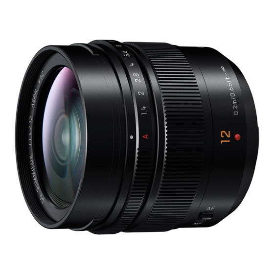
INTERCHANGEABLE LENS FOR DIGITAL CAMERA
"LUMIX DG SUMMILUX 12 mm/F1.4 ASPH."
Focal length
Aperture type
Maximum aperture
Minimum aperture value
Lens construction
In focus distance
Maximum image magnification
Optical image stabiliser
[AF/MF] switch
Mount
Angle of view
Filter diameter
Max. diameter
Overall length
Mass (Weight)
Dust-proof and splash-proof
H-X012
Component Repair
f=12 mm
(35 mm film camera equivalent: 24 mm)
9 diaphragm blades/circular aperture diaphragm
F1.4
F16
15 elements in 12 groups
(2 aspherical lenses, 1 ED lens, 2 UED lenses)
0.2 m (0.66 feet) to ∞ [from the focus distance reference line]
0.1× (35 mm film camera equivalent: 0.2×)
Not available
Available (Switching AF/MF)
"Micro Four Thirds Mount"
84°
62 mm
Approx. 70.0 mm (2.8 inch)
Approx. 70.0 mm (2.8 inch)
(from the tip of the lens to the base side of the lens mount)
Approx. 335 g (0.74 lb)
Available
ⓒ Panasonic Corporation 2017 Unauthorized copying and distribution is a violation of law.
Ver.1.0
Internal use only
Advertisement
Table of Contents

Subscribe to Our Youtube Channel
Related Manuals for Panasonic LUMIX H-X012


Summary of Contents for Panasonic LUMIX H-X012
- Page 1 Approx. 70.0 mm (2.8 inch) (from the tip of the lens to the base side of the lens mount) Approx. 335 g (0.74 lb) Mass (Weight) Dust-proof and splash-proof Available ⓒ Panasonic Corporation 2017 Unauthorized copying and distribution is a violation of law.
-
Page 2: Table Of Contents
TABLE OF CONTENTS PAGE 1 Service Navigation ・ ・ ・ ・ ・ ・ ・ ・ ・ ・ ・ ・ ・ ・ ・ ・ ・ ・ ・ ・ 1.1. Introduction ・ ・ ・ ・ ・ ・ ・ ・ ・ ・ 1.2. Important Notice 2 Exploded View ・ ・ ・ ・ ・ ・ ・ ・ ・ ・ ・ ・ ・ ・ ・ ・ ・ ・ ・ ・ 2.1. Lens Unit ・ ・ ・ ・ ・ ・ ・ ・ ・ ・ 2.2. Lens Body Unit 3 Replacement Parts List ・ ・ ・ ・ ・ ・ ・ ・ ・ ・ 4 Service Fixture & Tools ・ ・ ・ ・ ・ ・ ・ ・ ・ ・ ・ ・ ・ ・ ・ ・ ・ ・ ・ ・ 4.1. -
Page 3: Service Navigation
1 Service Navigation 1.1. Introduction This manual contains technical information, which allow service personnel's to understand and service this model. Please place orders using the parts list and not the drawing reference numbers. 1.2. Important Notice This manual is written for Micro Four Thirds Lens H-X012. As you may know, lens hates dust, soil, sand, fingerprint. -
Page 4: Exploded View
2 Exploded View 2.1. LENS UNIT 220: LENS BODY UNIT B213 B212 B211 201 (Kit) B202 B201 B203 B204 B205 201-1 B206 B207 B210 B208 B209... -
Page 5: Lens Body Unit
2.2. LENS BODY UNIT B227 B228 B226 B224 B225 B221 B222 221: LENS MAIN B229 B223 B230 B231 B232 B233 B234... -
Page 6: Replacement Parts List
3 Replacement Parts List Definition of Parts Supplier ・All parts are supplied from AVC-IMAGING. Ref.No. Part No. Part Name & Description Remarks SXW0298KIT LENS UNIT DVXE1008ZKIT DECORATION RING KIT 201-1 DVXE1008Z DECORATION RING UNIT DVXE1010Z 1ST LENS FRAME UNIT DVXE1011Z FRONT FRAME UNIT DVXE1017Z MOUNT CONTACT UNIT... -
Page 7: Service Fixture & Tools
4 Service Fixture & Tools 4.1. Fixture and Tools The following Fixture and Tools are used for checking and servicing this unit. Lens Cleaning Kit (BK) Torque Driver Ring Remover VFK1900BK RFKZ0542 DVKW1002ZA Spec:2-30N・cm *Only supplied 10 set/box. (Equiv.0,1-3kgf/cm) 1st Lens Frame Remover Collimeter Reference Camera DVKW1003ZA... -
Page 8: Maintenance
5 Maintenance 5.1. Dust / Dirt on the outer casing part(s) 1. Blow off the dust first, then sweep out the dust from narrower spaces with soft cleaning brush. 2. Wipe up the outer casing part with the dry fuzz-free cloth. 5.2. -
Page 9: Disassembly And Assembly Instructions
6 Disassembly and Assembly Instructions 6.1. Disassembly Instructions 6.1.1 Disassembly Flow Chart DISASSEMBLY DECORATION RING SHADING FRAME (with FRONT RING) L MOUNT UNIT 1ST LENS FRAME UNIT DUST PROOF RING FRONT FRAME UNIT LENS MOUNT SPACER Implementation of 1 to 3 of the Disassembly Procedure EARTH PLATE REAR FRAME UNIT... -
Page 10: Disassembly Procedure
6.1.2. Disassembly Procedure 1st Lens Frame Remover Important: (DVKW1003ZA) It must be performed inside of satisfied clean level. (Satisfied clean level: Less than class 10,000 (Federal Standard 209D)) 6.1.2.1. Removal of the Decoration Ring (with the Front Ring) The Decoration Ring (with Front Ring) has been fixed by screwing. - Page 11 6.1.2.4. Removal of the Shading Frame 3. Remove the Dust Proof Ring. 1. Remove 3 screws (A) and the Shading Frame. Dust Proof Ring 6.1.2.6. Removal of the Lens Mount Spacer 1. Remove the Lens Mount Spacer. Screw (A) Screw (A) x 3 6.1.2.5.
- Page 12 2. Remove 1 screws (E) and disconnect 1 connector. 3. Remove the Lens P.C.B. and the Mount Connect Unit. 3. Remove the Rear Frame Unit. Connector Screw (E) 6.1.2.9. Removal of the Focus Motor Unit Screw (E) 1. Remove 6 screws (G) and the Focus Motor Unit. Connector Screw (G) SILVER...
- Page 13 6.1.2.10. Removal of the Iris Unit and the Housing Rubber 1. Remove 5 screws (H). 2. Remove the Iris Unit and the Housing Rubber. Screw (H) Screw (H) Iris Unit Screw (H) x 5 Housing Rubber 6.1.2.11. Removal of the 3rd Lens Frame Unit (For Cleaning) 1.
-
Page 14: Assembly Instructions
6.2. Assembly Instructions 6.2.1 Assembly Flow Chart ASSEMBLY 3RD LENS FRAME UNIT IRIS UNIT FRONT FRAME UNIT (After CLEANING) FOCUS MOTOR UNIT 1ST LENS FRAME UNIT LENS MOUNT CONTACT UNIT FRONT RING LENS P.C.B. UNIT REAR FRAME UNIT DECORATION RING EARTH PLATE LENS MOUNT SPACER DUST PROOF RING... -
Page 15: Assembly Procedure
6.2.2. Assembly Procedure 6.2.2.3. Installation of the Focus Motor Unit 6.2.2.1. Installation of the 3rd Lens Frame Unit the Iris Unit (After cleaning) 1. Install the Focus Motor Unit. 1. Install the 3rd Lens Frame Unit. 2. Tighten 6 screw (G) by using the torque driver 2. - Page 16 6.2.2.4. Installation of the Lens P.C.B. Unit 6.2.2.5. Installation of the Rear Frame Unit and and the Lens Mount Contact Unit the Earth Plate 1. Connect FPC of the Lens Mount Connect Unit to 1. Install the Rear Frame Unit. connector.
- Page 17 6.2.2.6. Installation of the Lens Mount Spacer 2. Install the L Mount Unit. 1. Install the Lens Mount Spacer. 3. Tighten 1 screw (B) and 4 screws (C) by using the torque driver with specified torque. Screw (B) Lens Mount Spacer 6.2.2.7.
- Page 18 6.2.2.9. Installation of the Front Frame Unit 1st Lens Frame Remover 1. Install the Front Frame Unit. (DVKW1003ZA) Front Frame Unit 6.2.2.11. Installation of the Front Ring The Front Ring is fixed by screwing. 1. Install the Front Ring by firmly attacing the Ring Remover (DVKW1002ZA) and turning it clockwise.
- Page 19 6.2.2.12. Installation of the Decoration Ring 2. Pressed evenly by the Ring Remover (DVKW10002ZA). 1. Install the Decoration Ring as shown in the figure below. Ring Remover (DVKW1002ZA)
-
Page 20: Adjustment
7 Adjustment 7.1. Matrix Chart for Replaced Part and Necessary Adjustment The relation between Replaced part and Necessary Adjustment is shown in the following table. When concerned part is replaced, be sure to achieve the necessary adjustment(s). Necessary Adjustment Replaced Part Electrical Adjustment - - - DECORATION RING KIT... -
Page 21: Flow Chart For Adjustment
7.3. Flow Chart for Adjustment * Note Electrical Finish * NOTE: Implement the re-assembly and re-exchange of replacement parts. 7.4. Procedure for Adjustment 7.4.1. Electrical Adjustment Make Electrical Adjustment using PC with Adjustment Software. As for Adjustment conditions/procedure, consult the "Adjustment Manual" which is available in Adjustment Software. -
Page 22: Revision History
8 Revision History Ver. Date History ・First Issue 2017.03.30...
Need help?
Do you have a question about the LUMIX H-X012 and is the answer not in the manual?
Questions and answers