Advertisement
Quick Links
INTRODUCTION
Lunar Delay is a beginner/intermediate level build. You will need to know how to solder through hole
components. There is nothing too tricky, but there are a lot of components to solder and you will need to
make a vactrol. It's a good idea to read through this entire document before starting to build. The assembly
should take 4 to 8 hours to complete. The following tools are required:
- Soldering Iron
- Solder
- Flush Cutters
- Needle Nose Pliers or Tweezers
- Helping Hands & Lighter (for making the vactrol)
- Multimeter
This module has two PCBs. The kit comes with all components sorted into bags according to which
board they go to. Download the BOM for the complete and detailed list of parts.
BAG 1 / BOARD B
LUNAR DELAY
v1.3 Build Guide
1
Advertisement

Related Manuals for MidCentury Modular Lunar Delay


Summary of Contents for MidCentury Modular Lunar Delay
- Page 1 Build Guide INTRODUCTION Lunar Delay is a beginner/intermediate level build. You will need to know how to solder through hole components. There is nothing too tricky, but there are a lot of components to solder and you will need to make a vactrol.
- Page 2 BAG 1 / BOARD B Part Value Body Marking Resistor 510r Green Brown Black Black Brown Resistor Brown Black Black Brown Brown Resistor Red Red Black Brown Brown Resistor Brown Black Black Red Brown Resistor Brown Green Black Red Brown Resistor Red Black Black Red Brown Resistor...
- Page 3 BAG 1 / BOARD B Start by soldering the resistors. Resistors are not polarized, their orientation does not matter. There are 48 resistors in total so get comfortable, this step can take a while. Now move on to the IC sockets. There are four 14 pin sockets and two 16 pin sockets.
- Page 4 BAG 1 / BOARD B Next solder the ceramic capacitors. These are the small orange ones. They are not polarized, their orienta- tion does not matter. There is one 1n cap, four 220p caps, two 500p caps, four 560p caps, and seventeen 100n caps. Now do the two transistors.
- Page 5 BAG 1 / BOARD B Next up is the L7805 voltage regula- tor. Before you place it on the board, prepare bend here component bending its leads down at the point where they transition from thick to thin. A needle nose plier or pair of tweezers is handy for bending all three leads at once, which keeps them aligned with each other.
- Page 6 BAG 1 / BOARD B Place the 10 pin shrouded header on the back of the board. Before you solder any pins, make sure the orientation is correct. The header’s notch should match the notch drawn on the silkscreen. If it is soldered in the wrong position, the module won’t power on, and it will be a real pain to fix if all ten pins are soldered.
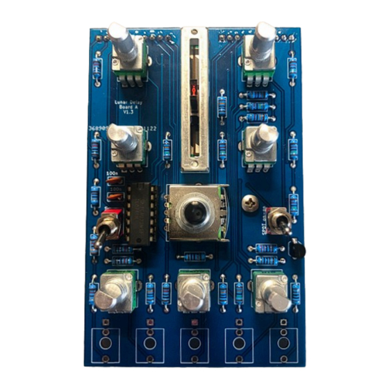
- Page 7 BAG 2 / BOARD A Get Board A out, open Bag 2, and organize the components. Once again, it’s a good idea to check the resistor values with your multimeter. Cut two 1x10 segments from both the male and female pin header strips. Keep in mind, when cutting female pin headers you will always lose one pin.
- Page 8 BAG 2 / BOARD A Part Value Body Marking Resistor Brown Black Black Brown Brown Resistor Red Red Black Brown Brown Resistor Blue Grey Black Brown Brown Resistor Brown Black Black Red Brown Resistor Brown Green Black Red Brown Resistor Orange Orange Black Red Brown Resistor Blue Grey Black Red Brown...
- Page 9 BAG 2 / BOARD A Begin Board A by soldering the resistors. There are two 1K, one 2K2, one 6K8, six 10K, four 15K, one 33K, one 68K, three 100K, two 150K, two 820K, and one 1M2. Nest, solder the two 100n ceramic caps, one tran- sistor, and one 14 pin IC socket.
- Page 10 BAG 2 / BOARD A Place the two male pin headers on the back of Board A, and solder just one pin on each strip. Make sure each header is flush against the PCB. If it isn’t, reflow the one pin you soldered while gently pressing the pin head- er toward the board.
- Page 11 BAG 2 / BOARD A Some of the front panel components need to be prepared before you place them on the board. Potenti- ometers may have anti-rotation tabs; if they do, cut those off. The rotary switch has an anti-rotation tab but do not cut it off.
- Page 12 BAG 2 / BOARD A With the front panel in place and all components firmly secured, now we can solder everything. Solder all jacks, potentiometers, toggle switches, and the rotary switch. Once all components are soldered, place the female pin headers onto their corresponding male head- ers attached to Board A.
- Page 13 This will ensure that all the knobs sit at the same height, the same consistent distance from the panel. Congratulations! You have successfully built a Lunar Delay. Enjoy your new module!
Need help?
Do you have a question about the Lunar Delay and is the answer not in the manual?
Questions and answers