Advertisement
Quick Links
INTRODUCTION
Dividers is an intermediate level build. You will need to know how to solder through hole components,
and some components are placed close together and must be soldered in a specific order. It's a good idea to
read through this entire document before starting to build. The assembly should take 2.5 to 3.5 hours to com-
plete. The following tools are required:
- Soldering Iron
- Solder
- Flush Cutters
- Needle Nose Pliers or Tweezers
- Multimeter
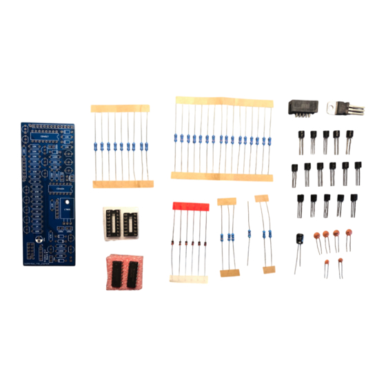
This module has two PCBs. The kit comes with all components sorted into bags according to which
board they go to. Download the BOM for the complete and detailed list of parts.
BAG 1 / BOARD B
Note: Board B can be v1.2 or v1.3, either one will work.
DIVIDERS
v1.3 Build Guide
1
Advertisement

Related Manuals for MidCentury Modular Dividers


Summary of Contents for MidCentury Modular Dividers
- Page 1 Build Guide INTRODUCTION Dividers is an intermediate level build. You will need to know how to solder through hole components, and some components are placed close together and must be soldered in a specific order. It’s a good idea to read through this entire document before starting to build.
- Page 2 BAG 1 / BOARD B Part Value Body Marking Resistor 100r Brown-Black-Black-Black-Brown Resistor Brown-Black-Black-Brown-Brown Resistor Brown-Black-Black-Orange-Brown Resistor Yellow-Violet-Black-Red-Brown Resistor 100K Brown-Black-Black-Orange-Brown Diode 1N4148 IC Socket DIP 14 IC Socket DIP 16 Voltage Regulator L7805 Pin Header Male 1x02 Capacitor 100n Capacitor Transistor 2N3904...
- Page 3 BAG 1 / BOARD B Next, solder the six diodes. Diodes are polarized, the correct orientation is indicated on the PCB. The dark stripe on one end of the diode must be on the same side as the stripe on the PCB silkscreen. Now move on to the IC sockets.
- Page 4 BAG 1 / BOARD B Next up is the L7805 voltage regulator. Before you place it on the board, prepare the component by bending its leads down at the point where they transition from thick to thin. A needle nose plier or pair or tweezers is handy for bending all bend here three leads at once, which keeps them aligned with each oth- er.
- Page 5 BAG 1 / BOARD B Now we can do the ceramic disk capacitors. These are the small orange ones. There are two 10n caps and four 100n caps. These are not polarized, their orientation does not matter. Next, place and solder all sixteen transistors. These are all 2n3904 NPN transistors. These must be placed in the correct orientation.
- Page 6 BAG 1 / BOARD B Now solder the single 10uF electrolytic capacitor. Electrolytic caps are polarized, the long lead goes into the hole marked with a “+”. Place the 10 pin shrouded header on the back of the board. Before you solder any pins, make sure the orientation is correct.
- Page 7 BAG 1 / BOARD B Pop the ICs in their sockets, making sure the notch on each IC is on the same side as the notch on its socket and the notch drawn on the PCB silkscreen. Then place this board aside and move on to Board A. BAG 2 / BOARD A Get Board A out, opent Bag 2, and organize the components.
- Page 8 BAG 2 / BOARD A Part Value Body Marking Resistor Brown-Black-Black-Brown-Brown Resistor Brown-Black-Black-Red-Brown Resistor Yellow-Violet-Black-Red-Brown Resistor 100K Brown-Black-Black-Orange-Brown Pin Header Male 1x5, 1x6, 1x7, 1x13 Rotary Switch SP8T Blue, 3mm Jacks Thonkiconn Pin Header Female 1x5, 1x6, 1x7, 1x13 Begin Board A by soldering the resistors. There are six 1K resistors, three 10K resistors, one 47K resistor and one 100K resistor.
- Page 9 BAG 2 / BOARD A Now, place all the panel mount components on the board, but do not solder them yet. LEDs are po- larized, make sure the long lead of each one goes into a hole marked with a “+”. The rotary switch also must be placed in a specific orientation - one side of the body is slightly rounded, this side should be facing toward the left side of the board when placed on the PCB.
- Page 10 BAG 2 / BOARD A With the front panel in place and all components firmly secured, now we can solder everything. Solder all jacks, LEDs, and the rotary switch. Once all components are soldered, place the female pin headers onto their corresponding male headers attached to Board A.
- Page 11 Power on your Dividers module. Leave the clock inputs unpatched, and send a gate to each of the Re- set inputs. The LEDs should now look like this: If your module is not working as expected, you will need to do some troubleshooting.
Need help?
Do you have a question about the Dividers and is the answer not in the manual?
Questions and answers