Table of Contents
Advertisement
Kodak Home Page
on Internet
Intranet
Table of Contents
© Eastman Kodak Company, 1999
{ServiceManual}{Production}{KodakServiceSupport}
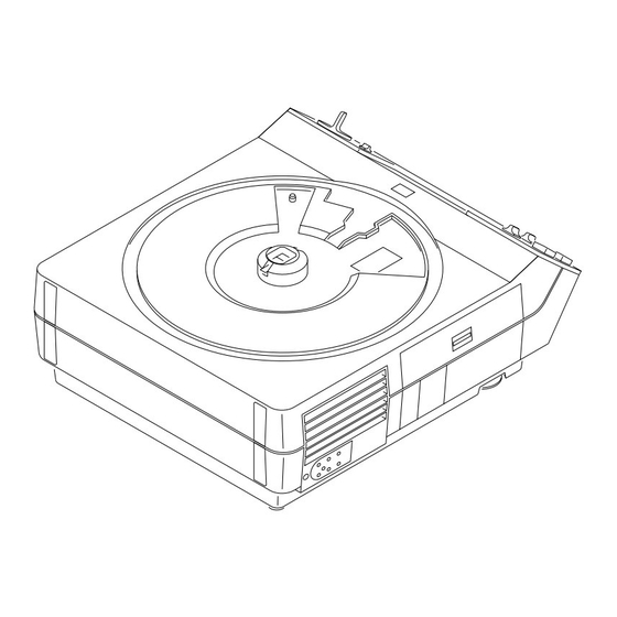
Kodak Carousel NEW LOOK PROJECTORS
Standard and Long Life
Models 4200, 4200-J, 4200-KK, 4400, 4600,
4600-KK, 5600, 5600-J, and 5600-KK
A100_0029HA
SERVICE MANUAL
for the
Publication No. SM5440-1
18NOV97
Supersedes SM5440-1
13MAY97
Advertisement
Table of Contents

Related Manuals for Kodak CAROUSEL NEW LOOK PROJECTOR


Summary of Contents for Kodak CAROUSEL NEW LOOK PROJECTOR
- Page 1 18NOV97 Supersedes SM5440-1 13MAY97 SERVICE MANUAL for the Kodak Carousel NEW LOOK PROJECTORS Standard and Long Life Models 4200, 4200-J, 4200-KK, 4400, 4600, 4600-KK, 5600, 5600-J, and 5600-KK Kodak Home Page on Internet Intranet Table of Contents A100_0029HA © Eastman Kodak Company, 1999...
-
Page 2: Table Of Contents
MOTOR......... - Page 3 NULL.........
-
Page 4: Replacements And Installations
[4] Remove the 6 Torx SCREWS from the LOWER HOUSING ASSEMBLY. [5] Pull the LOWER HOUSING ASSEMBLY off the TOP HOUSING. Installing the LOWER HOUSING ASSEMBLY [1] Do the replacement procedure for the LOWER HOUSING ASSEMBLY in reverse order. LOWER HOUSING SCREW (6) - Page 5 [14] Remove the FAN BELT and MECHANISM BELT off the MOTOR PULLEY. Use SPRING HOOK TL-1165. Caution Move the MOTOR to allow access to the parts; wires are still connected to the MOTOR. Do not cause damage to the MOTOR wires.
-
Page 6: Installing The Fan Shaft Assembly
Installing the FAN SHAFT ASSEMBLY Important When installing the FAN and MECHANISM BELTS, install the MECHANISM BELT on the small MOTOR PULLEY, and the FAN BELT on the large MOTOR PULLEY. [1] Do the removal procedure for the FAN BELT and SHAFT in reverse order. -
Page 7: Replacing The Motor
[2] Do the replacement procedure for the LOWER HOUSING ASSEMBLY. [3] Disconnect all wires from the MOTOR. [4] Cut the 2 WIRE TIES on the SMALL CIRCUIT BOARD between the MOTOR and MECHANISM ASSEMBLY. [5] Disconnect the 2 wires from the CYCLE SOLENOID on the SMALL CIRCUIT BOARD. -
Page 8: Replacing The Worm Pulley And Mechanism Belt
[1] Disconnect the main power. [2] Do the replacement procedure for the LOWER HOUSING ASSEMBLY. [3] Do the replacement procedure for the MOTOR except do not disconnect the wires from the MOTOR. [4] Remove the Torx SCREW from the WORM PULLEY ASSEMBLY. -
Page 9: Installing The Worm Pulley And Mechanism Belt
Installing the WORM PULLEY and MECHANISM BELT Important When installing the FAN and MECHANISM BELTS, install the MECHANISM BELT on the small MOTOR PULLEY, and the FAN BELT on the large MOTOR PULLEY. [1] Do the replacement procedure for the WORM PULLEY and MECHANISM BELT in reverse order. -
Page 10: Replacing The Thermal Fuse Assembly
[3] Cut and remove the necessary WIRE TIES. [4] Remove the 2 Torx SCREWS on the left side of the LOWER LIGHT BAFFLE ASSEMBLY. [5] Loosen the Torx SCREW on the right side of the LOWER LIGHT BAFFLE ASSEMBLY approximately 1/2 way. 18NOV97 – SM5440-1... -
Page 11: Installing The Lamp Module Receptacle
[8] Remove the 2 long Torx from the BLOWER COVER ASSEMBLY. [9] Lift the BLOWER COVER ASSEMBLY up. [10] Lift and move the PREHEAT DUCT up. [11] To remove the LAMP MODULE RECEPTACLE from the PREHEAT DUCT, compress the 2 TABS on the LAMP MODULE RECEPTACLE. PRE-HEAT DUCT... -
Page 12: Replacing The Cycle Solenoid Assembly
[7] Move the TAB on the WORM PULLEY ASSEMBLY out of the MECHANISM ASSEMBLY. [8] Lift and remove the WORM PULLEY ASSEMBLY. [9] Remove the 2 Hex 1/4 in. SCREWS from the 2 CYCLE SOLENOID GROMMETS. [10] Pull the CYCLE SOLENOID ASSEMBLY up and out. -
Page 13: Replacing The Mechanism Assembly
Installing the MECHANISM ASSEMBLY Important To insert the SELECT BUTTON into the hole in the SELECT LEVER when installing the MECHANISM ASSEMBLY, hold the SELECT BUTTON completely down. [1] Do the removal procedure for the MECHANISM ASSEMBLY in reverse order. -
Page 14: Replacing The Auto-Focus Bracket Assembly
[9] Remove the 2 Hex SCREWS from the CYCLE SOLENOID. [10] Remove the CYCLE SOLENOID. [11] Remove the Phillips SCREW from the AUTO-FOCUS BRACKET ASSEMBLY. [12] Pull and remove the AUTO-FOCUS BRACKET ASSEMBLY through the hole where the CYCLE SOLENOID was. SCREW... - Page 15 Replacements and Installations [7] Remove the DIRECTION LEVER SPRING from the DIRECTION LEVER. [8] Disconnect the LIFT LEVER SPRING from LIFT LEVER on the TOP PLATE of the MECHANISM ASSEMBLY. [9] Remove the RETARD SPRING. [10] Remove the 7 Torx SCREWS from the TOP PLATE of the MECHANISM ASSEMBLY.
- Page 16 SERVICE MANUAL LIFT LEVER LIFT LEVER SHAFT SELECT LEVER E-RING BEARING SELECT LEVER SPRING E-RING CAM STACK A091_0010HCA BEARING A091_0010HA ASSEMBLY 18NOV97 – SM5440-1...
-
Page 17: Installing The Cam Stack Assembly And Cycle Lever Assembly
Caution Keep both the CYCLE LEVER ASSEMBLY and the PLUNGER HALF CYCLE LEVER together and observe the orientation of both LEVERS. [27] Slide both the CYCLE LEVER and HALF CYCLE LEVER off the SHAFT. CYCLE SOLENOID SCREW (2) INDEX LEVER... -
Page 18: Replacing The Lamp Socket Terminal Assembly
[7] Remove the LAMP EJECTOR. [8] Remove the LAMP SOCKET TERMINAL ASSEMBLY. CONDENSER LENS HEAT ABSORBING TAB (2) GLASS A091_0018CCA A091_0018CA Installing the LAMP SOCKET TERMINAL ASSEMBLY [1] Do the replacement procedure for the LAMP SOCKET TERMINAL ASSEMBLY in reverse order. 18NOV97 – SM5440-1... -
Page 19: Replacing The Lens Mount Assembly - Auto Focus Model
[4] Remove the 3 SCREWS from the LENS MOUNT ASSEMBLY. [5] Lift and remove the LENS MOUNT ASSEMBLY. A100_0019GCA A100_0019GA Installing the LENS MOUNT ASSEMBLY - Auto Focus Models [1] Do the replacement procedure for the LENS MOUNT ASSEMBLY in reverse order. SM5440-1 – 18NOV97... -
Page 20: Replacing The Lens Mount Assembly - Non Auto Focus Model
[4] Remove the 3 SCREWS from the LENS MOUNT ASSEMBLY. [5] Lift and remove the LENS MOUNT ASSEMBLY. A100_0019GCA A100_0019GA Installing the LENS MOUNT ASSEMBLY - Non Auto Focus Model [1] Do the replacement procedure for the LENS MOUNT ASSEMBLY in reverse order. 18NOV97 – SM5440-1... -
Page 21: Replacing The Auto-Focus Switch Assembly
Installing the AUTO-FOCUS SWITCH ASSEMBLY Important Align the 2 TABS on the AUTO-FOCUS SWITCH with the FOCUS MOTOR BRACKET, checking that the end of the AUTO-FOCUS LEVER engages with the CYCLE SOLENOID PLUNGER. After the AUTO-FOCUS SWITCH is in the correct position, bend the LOCKING TAB to hold the AUTO FOCUS SWITCH in place. - Page 22 [2] Do the replacement procedure for the LOWER HOUSING ASSEMBLY. [3] Remove the FOCUS KNOB. Important It is necessary to push the AUTO-FOCUS BRACKET backward and forward to allow access to the SCREWS on the LENS MOUNT ASSEMBLY. [4] Remove the 3 SCREWS from the LENS MOUNT ASSEMBLY.
-
Page 23: Installing The Focus Shaft Assembly
Replacements and Installations Installing the FOCUS SHAFT ASSEMBLY Important Do the adjustments for the PHOTOCELL NULL and AUTO-FOCUS CLAMP after installation. See the Adjustments section. Replacing the FOCUS SHAFT ASSEMBLY - Non Auto-Focus Models Warning Dangerous Voltage [1] Disconnect the main power. -
Page 24: Installing The Focus Shaft Assembly
SERVICE MANUAL Installing the FOCUS SHAFT ASSEMBLY [1] Do the replacement procedure for the FOCUS SHAFT ASSEMBLY in reverse order. 18NOV97 – SM5440-1... -
Page 25: Adjustments
Important 1. The CYCLE SOLENOID must operate correctly to do this adjustment. 2. The MECHANISM ASSEMBLY does not have to be removed to do this adjustment. [2] Do the removal for the LOWER HOUSING ASSEMBLY. [3] Bend the CYCLE LEVER up or down. Use T-BAR TL-3003. -
Page 26: Adjusting The Indexer Lever Assembly
SERVICE MANUAL Adjustment Specification This adjustment adjusts the strobe and timing of the INDEXER LEVER. The gate edge of the black plastic of the INDEXER LEVER should be between the 2 holes at position 2. Adjusting the INDEXER LEVER ASSEMBLY... -
Page 27: Adjusting The Slide Lift Lever Manual, With Mechanism Out
Adjustment Specification Use MECHANISM RUNNING FIXTURE. Use TL-3001 to measure the height of the SLIDE LIFT LEVER. The LEVER should make contact with the low surface of TL-3001. The LEVER should not make contact with the high surface of TL-3001. -
Page 28: Adjusting The Focus Light Path - Auto Focus Models
[6] Set the projector to the LOW LAMP position. [7] Install the AUTO-FOCUS TARGET SLIDE TL-3002 until it is fully seated in the GATE MECHANISM. [8] Look through the PROJECTION LENS hole and observe the focus light path on the AUTO-FOCUS TARGET SLIDE TL-3002. -
Page 29: Adjusting The Null
SLIDE TL-3002. Check that the light image is correct. If not, do the Adjusting the FOCUS LIGHT PATH. [8] Check that the TAB on the CLAMP PAD ASSEMBLY is in the NULL position. If the TAB is not in the correct position, do the adjustment procedure for the NULL. -
Page 30: Adjusting The Photocell
SERVICE MANUAL Important If you cannot obtain the NULL position after doing the adjustment approximately 3 times, go to the adjustment procedure for the PHOTOCELL. light path T-BAR TL-3003 NULL position PROJECTION LENS AUTO-FOCUS CLAMP LEVER TARGET SLIDE A091_4031BCA A091_4031BA TL-3002 Adjustment Specification... - Page 31 [4] Energize the projector. [5] Set the projector to the LO-LAMP position. [6] Install and hold the AUTO FOCUS TARGET SLIDE TL-3002 until it is fully seated in the GATE MECHANISM. [7] Look through the PROJECTION LENS hole and observe the focus light path on the AUTO-FOCUS TARGET SLIDE TL-3002.
- Page 32 [14] Install the FAN COVER TOOL over the FAN area and the LAMP MODULE. See the Tools section. [15] Install and hold the AUTO FOCUS TARGET SLIDE TL-3002 until it is fully seated in the GATE MECHANISM. 18NOV97 – SM5440-1...
- Page 33 Adjustments [16] Set the projector to the LO-LAMP position. [17] Observe the image of the focus light path on the bottom of the FAN CAP; the light path should be in the center of the hole in the FAN CAP.
-
Page 34: Adjusting The Clamp Pad Assembly
Adjusting the DARK SHUTTER [1] Do the removal for the LOWER HOUSING. [2] Insert a thin SLIDE into the GATE MECHANISM; the DARK SHUTTER should open. [3] Check the the PRESSURE PAD is correctly aligned with the the DARK SHUTTER. - Page 35 Adjustments DARK SHUTTER PRESSURE A091_0013GCA A091_0013GA SM5440-1 – 18NOV97...
-
Page 36: Lubrication
SERVICE MANUAL Section 3: Lubrication Apply lubricant SUPER LUBE TL-4276 to the following parts and areas of the projector; see the illustrations. • FAN • INDEXER LEVER and TOP PLATE • WORM PULLEY ASSEMBLY • CAM STACK ASSEMBLY • CYCLE LEVERS •... - Page 37 Lubrication A100_0020GA A091_0023HA SM5440-1 – 18NOV97...
- Page 38 SERVICE MANUAL A091_0022DA 18NOV97 – SM5440-1...
-
Page 39: Tools
TL-3255 Torx DRIVER SET TL-4276 SUPER LUBE DIGITAL MULTIMETER The LOWER HOUSING ASSEMBLY is a part of the cooling function. To operate the projector with the LOWER HOUSING removed, make a FAN COVER TOOL. Cut here. COVER TOOL 11.5 cm (4.5 in.) -
Page 40: Specifications
Operating temperature • 4.5 C (40 F), 15% humidity in low • 49 C (120 F), 15% humidity in high • 21 - 27 C (70 - 80 F), 20 - 60% humidity optimum Cooling Fan speed is 2780 or 3000 RPMs, 1360 BTUs... - Page 41 Elevation 14 maximum front elevation assembly. Auto Focus System • After the initial focus adjustment, the auto- focus system will adjust for the difference in the slide position from slide to slide. This focus adjustment will occur within 1 second after the slide is inserted into the GATE.
-
Page 42: Diagnostics
LAMP VOLTAGE is white 74 V AC between brown and white for black LONG LIFE MODELS 117 V AC MOTOR A091_0006BCA A091_0006BA MAIN MOTOR PIN Colors Color brown violet yellow blue not used MAIN MOTOR PIN Voltages Resistance Voltage 3.1 W 24.4 V AC... -
Page 43: Photocell Voltages
Diagnostics PHOTOCELL Voltages PHOTOCELL A091_4036ACA A091_4036AA PHOTOCELL Voltages PINS Voltage 14.5 V ac 14.5 V ac 29 V ac 5-PIN REMOTE CORD PLUG Voltages BLACK WHITE FOCUS YELLOW YELLOW KODAK EC-3 REMOTE CONTROL A100_0001BC_ 5-PIN REMOTE PLUG Voltages Description white... -
Page 44: Small Component Board Assembly 256809 Voltages
SERVICE MANUAL SMALL COMPONENT BOARD ASSEMBLY 256809 Voltages W K R A V V O B Y SLIDE PROJECTOR BOARD A091_4034DC Description Component RED +, BLACK - Voltage TIMER Circuit + to - 32 V DC TIMER Circuit - G to + A... -
Page 45: Voltage Specifications - General Parts
Check The MOTOR does not operate. 1. Check the continuity across the THERMAL FUSE ASSEMBLY, and MOTOR FUSE. 2. Check that the primary voltage on the MAIN MOTOR is correct. 3. Check that the voltage on POWER SWITCH is correct. -
Page 46: Slide Transport Malfunctions
If there is a bind, the CAM will not rotate. 4. Check that the CAM SHAFT ASSEMBLY RATCHET SPRING is installed correctly. 5. If there is a bind in the CAM STACK, install a new CAM. 18NOV97 – SM5440-1... - Page 47 SOLENOID. 2. Check that the SPRING is on the DIRECTION LEVER. 3. Check for a bind in the DIRECTION LEVER ASSEMBLY. 4. Check that the DIRECTION LEVER LINK is in the correct position. SLIDE TRAY does not rotate freely when the 1.
-
Page 48: Focus Malfunctions
DARK SHUTTER SWITCH. After the FOCUS MOTOR energizes and 1. Remove R3 and install a new 68K W 1/4 W moves, the FOCUS MOTOR oscillates. RESISTOR (part 220040). 2. If there is still a malfunction, install a new PHOTOCELL. - Page 49 PHOTOCELL are correct. The voltage from 1 to 2 is 13.8 V ac. The voltage from 2 to 3 is 13.8 V ac. The voltage from 1 to 3 is 28 V ac. 5. Make a short• between 1 and 2; the FOCUS MOTOR should rotate.
- Page 50 4. Check that the voltages across the PHOTOCELL are correct. The voltage from 1 to 2 is 13.8 V ac. The voltage from 2 to 3 is 13.8 V ac. The voltage from 1 to 3 is 28 V ac. 5. Check that the PHOTOCELL HOUSING has 2 FILTERS.
- Page 51 Kodak, Carousel, and Wratten are trademarks. Printed in U.S.A. • sm5440_1.fm EASTMAN KODAK COMPANY Rochester, NY 14650...
Need help?
Do you have a question about the CAROUSEL NEW LOOK PROJECTOR and is the answer not in the manual?
Questions and answers