Toro 03699 Operator's Manual
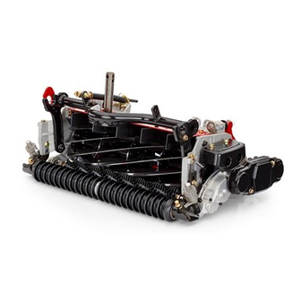
8 and 11 blade dpa cutting unit
Hide thumbs
Also See for 03699:
- Operator's manual (28 pages) ,
- Operator's manual (28 pages) ,
- Operator's manual (24 pages)
Table of Contents
Advertisement
Quick Links
Advertisement
Table of Contents

Related Manuals for Toro 03699


Summary of Contents for Toro 03699
- Page 1 Form No. 3392-112 Rev A 8 and 11 Blade DPA Cutting Unit Reelmaster ® 6000-D Series Traction Unit Model No. 03698—Serial No. 315000001 and Up Model No. 03699—Serial No. 315000001 and Up *3392-112* A Register at www.Toro.com. Original Instructions (EN)
-
Page 2: Table Of Contents
You are responsible for operating the product properly and safely. You may contact Toro directly at www.Toro.com for product Contents safety and operation training materials, accessory information, help finding a dealer, or to register your product. -
Page 3: Safety
Toro replacement parts and accessories replace it before operation is commenced. Also tighten to keep the Toro all Toro. Never use "will-fit" any loose nuts, bolts, and screws to ensure cutting unit is replacement parts and accessories made by other in safe operating condition. -
Page 4: Setup
Setup Loose Parts Use the chart below to verify that all parts have been shipped. Procedure Description Qty. Cutting unit Inspect the cutting unit. – No parts required Remove the tipper assemblies. Lift chain Chain bracket U-bolt 10/14 Mount lift brackets and chains. Screw Washer Use the kickstand when tipping the... -
Page 5: Inspecting The Cutting Unit
Inspecting the Cutting Unit Parts needed for this procedure: Cutting unit Procedure Figure 3 After the cutting unit is removed from the box, inspect the 1. Pivot rod 2. Tipper support bracket following: w/roller 1. Check each end of the reel for grease. Note: The tipper bracket with the roller and the tipper Note: Grease should be visibly evident in the reel support brackets are not required when operating the... - Page 6 3. On lift arm #4 the bracket should be rotated to the left 5. On lift arms #6 and #7, position the brackets and 10 degrees from vertical (Figure U-bolts 36.8 cm (14.5 inches) behind the center line of the pivot knuckle (Figure Note: Rotate the brackets 10 degrees to the outboard side of the machine.
-
Page 7: Using The Cutting Unit Kickstand
To open the rear shield (Figure 9), loosen the cap screw securing the shield to the left side plate, rotate the shield to the open position and tighten the cap screw. Using the Cutting Unit Kickstand Parts needed for this procedure: Kickstand (supplied with traction unit) Procedure Whenever the cutting unit has to be tipped to expose the... -
Page 8: Installing The Cutting Units
Note: Remove the counter weight (Figure 11). Installing the Cutting Units Parts needed for this procedure: Large O-ring Screw Procedure 1. Insert a thrust washer onto horizontal shaft of pivot knuckle as shown in Figure Figure 11 1. Counter weight 2. - Page 9 Figure 14 1. Lift chain 2. Snapper pin 9. Coat the spline of the reel motor with clean grease. 10. Oil the reel motor O-ring and install it onto the motor flange. 11. Install the motor by rotating it clockwise so that the motor flanges clear the cap screws (Figure 15).
-
Page 10: Product Overview
Product Overview Specifications Weight Cutting Unit 8 Blade 67 kg (147 lb) 11 Blade 69 kg (151 lb) Cutting Unit Accessories and Kits Full Front Roller: Helps produce more pronounced striping (repeated cutting in the same direction/path), however, Note: see parts catalog for part numbers effective height-of-cut is raised and quality of cut is reduced. -
Page 11: Operation
25 mm (1 inch) in from the end of the bedknife on the right hand side of the cutting unit. • Shim 0.0508 mm (0.002 inch)—Toro part number Putting an identifying mark on this blade will make 125-5611 subsequent adjustments easier. Insert the 0.05 mm •... - Page 12 3. Side plate mounting flange screws. 2. Roller bracket 10. Test the cutting performance by inserting a long strip of cutting performance paper (Toro part number 2. Raise rear of cutting unit and place a block under 125-5610) between reel and bedknife, perpendicular bedknife.
-
Page 13: Height-Of-Cut Chart Terms
Height-of-Cut Chart Terms Rear Spacers The number of rear spacers determines the aggressiveness of Height-of-Cut Setting (HOC) cut for the cutting unit. For a given height-of-cut, adding spacers, below the side plate mounting flange, increases the The desired Height-of-Cut. aggressiveness of the cutting unit. All cutting units on a given machine must be set to the same aggressiveness of cut Bench Set Height-of-Cut (Number of rear spacers, part no. -
Page 14: Height-Of-Cut Chart
Height-of-Cut Chart HOC Setting Aggressiveness of Cut No. of Rear Spacers With Groomer kits installed 0.64 cm (0.250 inches) Less Normal More 0.95 cm (0.375 inches ) Less Normal More 1.27 cm (0.500 inches) Less Normal More 1.56 cm (0.625 inches) Less Normal More... - Page 15 Adjusting the Height-of-Cut Note: For heights of cut greater than 2.54 cm (1.00 inch) the High Height-of-Cut Kit must be installed. 1. Loosen locknuts securing height-of-cut arms to cutting unit side plates (Figure 23). Figure 25 Figure 23 Important: When set properly, the rear and front 1.
- Page 16 3. If excessive contact/reel drag is evident it will be either necessary to backlap, reface the front of the bedknife, or regrind the cutting unit to achieve the sharp edges needed for precision cutting (Refer to the Toro Manual for Sharpening Reel and Rotary Mowers, Form No. 09168SL) Important: Light contact is preferred at all times.
-
Page 17: Servicing The Bedknife
Servicing the Bedknife The bedknife service limits are listed in the following charts. Important: Operating the cutting unit with the bedknife below the service limit may result in poor after-cut appearance and reduce the structural integrity of the bedknife for impacts. Bedknife Service Limit Chart Bedknife Part No. -
Page 18: Maintenance
Maintenance Lubrication Each cutting unit has 6 grease fittings (Figure 30) that must be lubricated regularly with No. 2 General-Purpose, Lithium-Base grease. The lubrication points are front roller (2), rear roller (2) and reel bearing (2). 1. Wipe each grease fitting with a clean rag. Figure 31 2. -
Page 19: Servicing The Bedbar
play of the reel exists. If adjusting nut does not eliminate reel end play, replace reel bearings. Note: Reel bearings do not require preload. Over tightening reel bearing adjuster nut will damage reel bearings. 4. Retighten set screw securing bearing adjusting nut to bearing housing. -
Page 20: Servicing The Roller
Refer to your parts catalog or contact your (Figure 38) are available for servicing the roller. The Authorized Toro Distributor for assistance. Roller Rebuild Kit includes all the bearings, bearing Figure 38 1. Roller Rebuild Kit (Part No. 114–5430) 6. - Page 21 Notes:...
- Page 22 The method of transmission shall be electronic transmittal. This machinery shall not be put into service until incorporated into approved Toro models as indicated on the associated Declaration of Conformity and in accordance with all instructions, whereby it can be declared in conformity with all relevant Directives.
- Page 23 The Way Toro Uses Information Toro may use your personal information to process warranty claims, to contact you in the event of a product recall and for any other purpose which we tell you about. Toro may share your information with Toro's affiliates, dealers or other business partners in connection with any of these activities. We will not sell your personal information to any other company.
- Page 24 Countries Other than the United States or Canada Customers who have purchased Toro products exported from the United States or Canada should contact their Toro Distributor (Dealer) to obtain guarantee policies for your country, province, or state. If for any reason you are dissatisfied with your Distributor's service or have difficulty obtaining guarantee information, contact the Toro importer.
Need help?
Do you have a question about the 03699 and is the answer not in the manual?
Questions and answers