Table of Contents
Advertisement
Available languages
Available languages
Quick Links
Copyright Notice:
Copyright Notice:
Copyright Notice:
Copyright Notice:
Copyright Notice:
No part of this installation guide may be reproduced, transcribed, transmitted, or trans-
lated in any language, in any form or by any means, except duplication of documen-
tation by the purchaser for backup purpose, without written consent of ASRock Inc.
Products and corporate names appearing in this guide may or may not be registered
trademarks or copyrights of their respective companies, and are used only for identifica-
tion or explanation and to the owners' benefit, without intent to infringe.
Disclaimer:
Disclaimer:
Disclaimer:
Disclaimer:
Disclaimer:
Specifications and information contained in this guide are furnished for informational
use only and subject to change without notice, and should not be constructed as a
commitment by ASRock. ASRock assumes no responsibility for any errors or omissions
that may appear in this guide.
With respect to the contents of this guide, ASRock does not provide warranty of any kind,
either expressed or implied, including but not limited to the implied warranties or
conditions of merchantability or fitness for a particular purpose. In no event shall
ASRock, its directors, officers, employees, or agents be liable for any indirect, special,
incidental, or consequential damages (including damages for loss of profits, loss of
business, loss of data, interruption of business and the like), even if ASRock has been
advised of the possibility of such damages arising from any defect or error in the guide
or product.
This device complies with Part 15 of the FCC Rules. Operation is subject to the
following two conditions:
(1) this device may not cause harmful interference, and
(2) this device must accept any interference received, including interference that
may cause undesired operation.
CALIFORNIA, USA ONLY
The Lithium battery adopted on this motherboard contains Perchlorate, a toxic
substance controlled in Perchlorate Best Management Practices (BMP) regulations
passed by the California Legislature. When you discard the Lithium battery in
California, USA, please follow the related regulations in advance.
"Perchlorate Material-special handling may apply, see
www.dtsc.ca.gov/hazardouswaste/perchlorate"
ASRock Website: http://www.asrock.com
Copyright©2006 ASRock INC. All rights reserved.
ASRock P4i65G Motherboard
Published November 2006
1 1 1 1 1
Advertisement
Table of Contents

Related Manuals for ASROCK P4I65G


Summary of Contents for ASROCK P4I65G
- Page 1 ASRock. ASRock assumes no responsibility for any errors or omissions that may appear in this guide. With respect to the contents of this guide, ASRock does not provide warranty of any kind, either expressed or implied, including but not limited to the implied warranties or conditions of merchantability or fitness for a particular purpose.
-
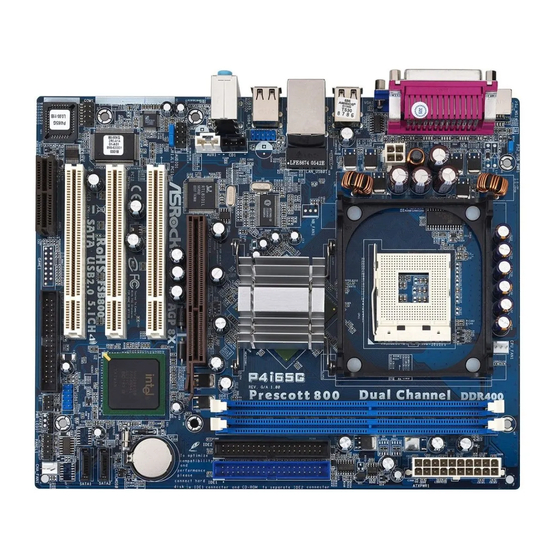
Page 2: Motherboard Layout
Chassis Speaker Header (SPEAKER 1) CPU Heatsink Retention Module Infrared Module Header (IR1) CPU Fan Connector (CPU_FAN1) Floppy Connector (FLOPPY1) 184-pin DDR DIMM Slots (DDR1- 2) AMR Slot (AMR1) ATX Power Connector (ATXPWR1) BIOS FWH Chip Primary IDE Connector (IDE1, Blue) -
Page 3: Asrock I/O Plus
USB 2.0 Ports (USB01) RJ-45 Port USB 2.0 Ports (USB23) Line In (Light Blue) VGA Port Line Out (Lime) PS/2 Keyboard Port (Purple) Microphone (Pink) PS/2 Mouse Port (Green) Shared USB 2.0 Ports (USB45) 3 3 3 3 3 ASRock P4i65G Motherboard... -
Page 4: Package Contents
This Quick Installation Guide contains introduction of the motherboard and step-by- step installation guide. More detailed information of the motherboard can be found in the user manual presented in the Support CD. Because the motherboard specifications and the BIOS software might be updated, the content of this manual will be subject to change without notice. -
Page 5: Specifications
Specifications Specifications Specifications Specifications Specifications Platform - Micro ATX Form Factor: 9.6-in x 7.8-in, 24.4 cm x 19.8 cm ® ® ® - Socket 478 for Intel Pentium 4 / Celeron D (Prescott, Northwood, Willamate) processors - FSB 800/533/400 MHz... - Page 6 - CD in header - AUX in header - Front panel audio connector - 2 x USB 2.0 headers (support 4 USB 2.0 ports; 2 of them are shared with USB4_5) (see CAUTION 8) BIOS Feature - 4Mb AMI BIOS - AMI Legal BIOS - Supports “Plug and Play”...
- Page 7 To improve heat dissipation, remember to spray thermal grease between the CPU and the heatsink when you install the PC system. Do NOT use a 3.3V AGP card on the AGP slot of this motherboard! It may cause permanent damage! ®...
-
Page 8: Pre-Installation Precautions
The CPU fits only in one correct orientation. DO NOT force the CPU into the socket to avoid bending of the pins. STEP 4: When the CPU is in place, press it firmly on the socket while you push down the socket lever to secure the CPU. The lever clicks on the side tab to indicate that it is locked. -
Page 9: Installation Of Memory Modules (Dimm)
Unlock a DIMM slot by pressing the retaining clips outward. Step 2. Align a DIMM on the slot such that the notch on the DIMM matches the break on the slot. The DIMM only fits in one correct orientation. It will cause permanent damage to the motherboard and the DIMM if you force the DIMM into the slot at incorrect orientation. -
Page 10: Expansion Slots (Pci,Agp And Amr Slots)
PCI slots: The PCI slots are used to install expansion cards that have the 32-bit PCI interface. AGP slot: The AGP slot is used to install a graphics card. The ASRock AGP slot has a special design of clasp that can securely fasten the inserted graphics card. -
Page 11: Jumpers Setup
Note: To select +5VSB, it requires 2 Amp and higher standby current provided by power supply. (see p.2 No. 25) (see p.2 No. 25) Note: If the jumpers JL1 and JR1 are short, both the front panel and the rear panel audio connectors can work. Clear CMOS (CLRCMOS0, 2-pin jumper) 2-pin jumper (see p.2 No. -
Page 12: Onboard Headers And Connectors
FDD Connector (33-pin FLOPPY1) (see p.2 No. 20) the red-striped side to Pin1 Note: Make sure the red-striped side of the cable is plugged into Pin1 side of the connector. Primary IDE Connector (Blue) Secondary IDE Connector (Black) (39-pin IDE1, see p.2 No. 8) (39-pin IDE2, see p.2 No. - Page 13 ASRock I/O Plus provides you 6 ready-to-use USB 2.0 ports on (9-pin USB67) the rear panel. If the rear USB (see p.2 No. 15) ports are not sufficient, this USB 2.0 header is available to support 2 extra USB 2.0 ports.
- Page 14 1. +5VA is used for audio power only, please don’t connect it to any other power, such as USB. 2. HD (Azalia) audio front panel and AC’97 audio front panel have different pin-definition. Incorrect connection of the audio front panel and the front panel audio header may cause permanent damage to this motherboard.
-
Page 15: Untied Overclocking Technology
Host Frequency” option of BIOS setup to [Auto], which will show you the actual CPU host frequency in the following item. Therefore, CPU FSB is untied during overclocking, but AGP / PCI bus is in the fixed mode so that FSB can operate under a more stable overclocking environment. -
Page 16: Bios Information
ME / 2000 / XP. The Support CD that came with the motherboard contains necessary drivers and useful utilities that will enhance motherboard features. To begin using the Support CD, insert the CD into your CD-ROM drive. It will display the Main Menu automatically if “AUTORUN” is enabled in your computer. If the Main Menu does not appear automatically, locate and double-click on the file “ASSETUP.EXE”... - Page 17 ASRock P4i65G Motherboard...
- Page 18 ® ® ® ® ® ® ASRock P4i65G Motherboard...
- Page 19 ® ® ASRock P4i65G Motherboard...
- Page 20 ASRock P4i65G Motherboard...
- Page 21 ASRock P4i65G Motherboard...
- Page 22 ASRock P4i65G Motherboard...
- Page 23 ASRock P4i65G Motherboard...
- Page 24 ASRock P4i65G Motherboard...
- Page 25 “ ” SATA2 SATA1 ASRock P4i65G Motherboard...
- Page 26 AUX1 ASRock P4i65G Motherboard...
- Page 27 ASRock P4i65G Motherboard...
- Page 28 ASRock P4i65G Motherboard...
- Page 29 ® ® ASRock P4i65G Motherboard...
- Page 30 1. Einführung 1. Einführung 1. Einführung Wir danken Ihnen für den Kauf des ASRock P4i65G Motherboard, ein zuverlässiges Produkt, welches unter den ständigen, strengen Qualitätskontrollen von ASRock gefertigt wurde. Es bietet Ihnen exzellente Leistung und robustes Design, gemäß der Verpflichtung von ASRock zu Qualität und Halbarkeit.
-
Page 31: Spezifikationen
Spezifikationen Spezifikationen Spezifikationen Spezifikationen Spezifikationen Plattform - Micro ATX-Formfaktor: 24.4 cm x 19.8 cm; 9.6 Zoll x 7.8 Zoll ® ® ® - Socket 478 für Intel Pentium 4 / Celeron D (Prescott, Northwood, Willamate) Prozessoren - FSB 800/533/400 MHz - Unterstützt Hyper-Threading-Technologie... - Page 32 Beachten Sie bitte, dass Overclocking, einschließlich der Einstellung im BIOS, Anwenden der Untied Overclocking-Technologie oder Verwenden von Overclocking-Werkzeugen von Dritten, mit einem gewissen Risiko behaftet ist. Overclocking kann sich nachteilig auf die Stabilität Ihres Systems auswirken oder sogar Komponenten und Geräte Ihres Systems beschädigen.
- Page 33 Shutdown durch. Bevor Sie das System neu starten, prüfen Sie bitte, ob der CPU-Lüfter am Motherboard richtig funktioniert, und stecken Sie bitte den Stromkabelstecker aus und dann wieder ein. Um die Wärmeableitung zu verbessern, bitte nicht vergessen, etwas Wärmeleitpaste zwischen CPU und Kühlkörper zu sprühen.
- Page 34 Unterlage, oder zurück in die Tüte, mit der die Komponente geliefert wurde. 2.1 CPU Installation Schritt 1: Öffnen Sie den CPU-Sockel, indem sie den Hebel leicht zur Seite und dann nach oben ziehen, auf einen Winkel von 90°. Schritt 2: Halten Sie die CPU korrekt ausgerichtet über den Sockel, so dass die markierte Ecke der CPU zum Hebelgelenk zeigt.
- Page 35 Öffnen Sie einen DIMM-Slot, indem Sie drücken. Schritt 2: Richten Sie das DIMM-Modul so über dem Slot aus, dass das Modul mit der Kerbe in den Slot passt. Die DIMM-Module passen nur richtig herum eingelegt in die Steckplätze. Falls Sie versuchen, die DIMM-Module mit Gewalt falsch herum in die Steckplätze zu zwingen, führt dies zu dauerhaften...
- Page 36 2.3 Er 2.3 Er weiterungssteckplätze: (PCI-, A -, und AMR -Slots): Es stehen 3 PCI-, 1 AGP-, und 1 AMR-Slot auf dem P4i65G Motherboard zur Verfügung. PCI-Slots: PCI-Slots werden zur Installation von Erweiterungskarten mit dem 32bit PCI-Interface genutzt. AGP-Slot: Der AGP-Steckplatz dient zur Installation einer Grafikkarte. Der ASRock AGP-Steckplatz hat speziell entwickelte Klammern, die die eingefügte Grafikkarte sicher festhalten.
-
Page 37: Einstellung Der Jumper
(siehe S.2 - Nr. 1) und die PS/2 oder USB- Weckfunktionen zu aktivieren. Hinweis: Um +5VSB nutzen zu können, muss das Netzteil auf dieser Leitung 2A oder mehr leisten können. (siehe S.2 - Nr. 25) (siehe S.2 - Nr. 25) Hinweis: Sind die Jumper JL1 und JR1 gesetzt funktionieren beide Audioanschlüsse, Front- und Rückseite. - Page 38 Floppy-Laufwerk (33-Pin FLOPPY1) die rotgestreifte Seite auf Stift 1 (siehe S.2 - Nr. 20) Hinweis: Achten Sie darauf, dass die rotgestreifte Seite des Kabel mit der Stift 1- Seite des Anschlusses verbunden wird. Primärer IDE-Anschluss (blau) Sekundärer IDE-Anschluss (schwarz) (39-pin IDE1, siehe S.2 - Nr. 8) (39-pin IDE2, siehe S.2 - Nr.
- Page 39 Serial ATA- (SATA-) Sie können beide Enden des Datenkabel SATA-Datenkabels entweder mit der SATA-Festplatte oder dem SATA-Anschluss am Mainboard verbinden. Serial ATA- (SATA-) Verbinden Sie das schwarze Stromversorgungskabel Ende des SATA-Netzkabels mit dem Netzanschluss am Laufwerk. (Option) Verbindung zum Verbinden Sie dann das weiße...
- Page 40 Anschlussmöglichkeit und Kontrolle über Audio-Geräte. 1. +5VA wird nur zur Audio-Stromversorgung verwendet. Bitte schließen Sie diesen Anschluss nicht an andere stromführende Geräte, wie USB- Geräte an. 2. Das HD- (Azalia) Frontaudio-Anschlussfeld und das AC’97-Frontaudio- Anschlussfeld verfügen über unterschiedliche Pinbelegungen. Der falsche Anschluss von Frontaudio-Anschlussfeld und Frontaudio-Anschlussleiste kann dauerhafte Schäden am Motherboard verursachen.
- Page 41 Verbinden Sie die ATX- Stromversorgung mit diesem (20-pin ATXPWR1) Header. (siehe S.2 - No. 7) Anschluss für Beachten Sie bitte, dass Sie eine 12V-ATX-Netzteil Stromversorgung mit ATX 12- Volt-Stecker mit diesem (4-pin ATX12V1) Anschluss verbinden müssen, (siehe S.2 - No. 2) damit ausreichend Strom geliefert werden kann.
- Page 42 2.6 Serial A 2.6 Serial A 2.6 Serial AT T T T T A A A A A - (SA - (SA - (SA - (SAT T T T T A) F A) F A) F A) Festplatteninstallation estplatteninstallation estplatteninstallation estplatteninstallation 2.6 Serial A...
- Page 43 CD information Dieses Motherboard unterstützt eine Reiche von Microsoft Windows Betriebssystemen: 98 SE / ME / 2000 / XP. Die Ihrem Motherboard beigefügte Support-CD enthält hilfreiche Software, Treiber und Hilfsprogramme, mit denen Sie die Funktionen Ihres Motherboards verbessern können Legen Sie die Support-CD zunächst in Ihr CD-ROM-Laufwerk ein.
- Page 44 Site web ASRock, http://www.asrock.com 1.1 Contenu du paquet Carte mère ASRock P4i65G (Facteur de forme Micro ATX : 9.6 pouces x 7.8 pouces, 24.4 cm x 19.8 cm) Guide d’installation rapide ASRock P4i65G CD de soutien ASRock P4i65G Un câble ruban IDE Ultra ATA 66/100 80 conducteurs Un câble ruban pour un lecteur de disquettes 3,5 pouces...
-
Page 45: Spécifications
- ASRock U-COP (voir ATTENTION 6) - Garde d’échec au démarrage (B.F.G.) Slot d’extension - 3 x slots PCI - 1 x slot AGP, support des cartes AGP 1.5V, 8X / 4X (voir ATTENTION 7) - 1 x slot AMR VGA sur carte - Intel ®... - Page 46 - FCC, CE, WHQL ATTENTION Il est important que vous réalisiez qu’il y a un certain risque à effectuer l’overclocking, y compris ajuster les réglages du BIOS, appliquer la technologie Untied Overclocking, ou utiliser des outils de tiers pour l’overclocking. L’overclocking peut affecter la stabilité de votre système, ou même causer des dommages aux composants et dispositifs de votre...
- Page 47 23 du manuel de l’utilisateur sur le CD technique. Cette carte mère prend en charge la technologie Untied Overclocking. Veuillez lire “La technologie de surcadençage à la volée” à la page 56 pour plus d’informations. Cette carte mère supporte la Technologie de Mémoire à Canal Double.
- Page 48 Etape 1. Déverrouillez le support en relevant le levier selon un angle de 90 Etape 2. Mettez en place le CPU au dessus du support de telle façon que l’angle portant une marque corresponde à la base du levier du support.
- Page 49 2.2 Installation des modules mémoire (DIMM) 2.2 Installation des modules mémoire (DIMM) La carte mère P4i65G possède deux emplacements DIMM DDR (Double Débit de données) 184 broches, et prend en charge la technologie Dual Channel Memory. Pour la configuration Double canal, vous devez toujours installer deux modules de mémoire identiques (mêmes marque, vitesse, dimensions et type de chip) dans les...
-
Page 50: Installation D'une Carte D'extension
2.3 Slot d’extension (Slots PCI, AGP, et AMR) 2.3 Slot d’extension (Slots PCI, AGP, et AMR) IIl y a 3 slots PCI, 1 slot AGP, et 1 slot AMR sur les cartes mères P4i65G. Slots PCI: Les slots PCI sont utilisés pour installer des cartes d’extension dotées d’une interface PCI 32 bits. - Page 51 Note: Pour sélectionner +5VSB, il faut obligatoirement 2 Amp et un courant standby supérieur fourni par l’alimentation. (voir p.2 No. 25) (voir p.2 No. 25) Note: Si les cavaliers JL1 et JR1 sont reliés, les connecteurs audio du panneau avant et du panneau arrière peuvent fonctionner. Effacer la CMOS (CLRCMOS0, le cavalier le cavalier à...
- Page 52 (FLOPPY1 br. 33) le côté avec fil rouge côté Broche1 (voir p.2 No. 20) Note: Assurez-vous que le côté avec fil rouge du câble est bien branché sur le côté Broche1 du connecteur. Connecteur IDE primaire (bleu) Connecteur IDE secondaire (noir) (39-pin IDE1, voir p.2 No.
- Page 53 électrique. En-tête USB 2.0 ASRock I/O Plus vous apporte 6 ports USB 2.0 par défaut sur (USB67 br.9) le panneau arrière. Si le nombre (voir p.2 No. 15) des ports USB à l’arrière n’est pas suffisant, cette En-tête USB 2.0 (USB67) permet de...
- Page 54 (voir p.2 No. 26) audio. 1. + 5VA n’est utilisé que pour l’alimentation audio, veuillez ne pas la brancher à toute autre alimentation, tel que l’USB. 2. Le panneau frontal audio HD (Azalia) et le panneau frontal audio AC’97 ont des définitions de broches différentes-.
- Page 55 Veuillez noter qu’il est nécessaire 12V ATX de connecter une unité d’alimentation électrique avec (ATX12V1 br. 4) prise ATX 12V sur ce connecteur (voir p.2 No. 2) afin d’avoir une alimentation suffisante. Faute de quoi, il ne sera pas possible de mettre sous tension.
- Page 56 [Auto], ce qui vous indiquera la fréquence d’hôte de l’UC courante dans l’item suivant. Par conséquent, le bus FSB de l’UC n’est pas lié pendant le surcadençage, mais le bus AGP/PCI est en mode fixe, si bien que le bus FSB peut opérer dans un environnement de surcadençage plus stable.
- Page 57 Cette carte mère supporte divers systèmes d’exploitation Microsoft Windows: 98 SE / ME / 2000 / XP. Le CD technique livré avec cette carte mère contient les pilotes et les utilitaires nécessaires pour améliorer les fonctions de la carte mère.
-
Page 58: Contenuto Della Confezione
Grazie per aver scelto una scheda madre ASRock P4i65G, una scheda madre affidabile prodotta secondo i severi criteri di qualità ASRock. Le prestazioni eccellenti e il design robusto si conformano all’impegno di ASRock nella ricerca della qualità e della resistenza. - Page 59 - Boot Failure Guard (B.F.G.) Slot di - 3 x slot PCI espansione - 1 x slot AGP, supporta scheda AGP a 1.5V, modelli 8X / 4X (vedi ATTENZIONE 7) - 1 x slot AMR VGA su scheda - Intel ®...
- Page 60 - 20-pin collettore alimentazione ATX - 4-pin connettore ATX 12V - Connettori audio interni - Connettore audio sul pannello frontale - 2 x Collettore USB 2.0 (supporto di 4 porte USB 2.0, 2 delle quali condivise con USB4_5) (vedi ATTENZIONE 8) BIOS...
- Page 61 NON usare schede AGP da 3,3 V nello slot AGP di questa motherboard! Ciò potrebbe provocare danni permanenti! La Gestione Risorse per USB 2.0 funziona perfettamente con Microsoft ®...
-
Page 62: Installazione
Leggere le seguenti precauzioni prima di installare componenti delle schede madri o di cambiare le impostazioni delle schede madri. 1. Togliere il cavo dalla presa elettrica prima di toccare le componenti. In caso contrario la schedamadre, le periferiche, e/o i componenti possono subire gravi danni. - Page 63 2.2 Installazione dei moduli di memoria (DIMM) 2.2 Installazione dei moduli di memoria (DIMM) La motherboard P4i65G dispone di due slot DIMM DDR (Double Data Rate) a 184 pin e supporta la tecnologia Dual Channel Memory. Per attivare la configurazione Dual Channel Memory bisogna installare sempre due moduli di memoria identici (stessa marca, velocità, dimensioni e tipo di chip) negli slot DIMM.
- Page 64 2.3 Slot di espansione (Slot PCI, Slot AGP, e Slot AMR) 2.3 Slot di espansione (Slot PCI, Slot AGP, e Slot AMR) Esistono 3 slot PCI, 1 slot AGP, e 1 slot AMR su entrambe le schede madri P4i65G. Slot PCI: Sono utilizzati per installare schede di espansione con Interfaccia PCI a 32-bit.
- Page 65 Nota: Per selezionare +5VSB, si richiedono almeno 2 Ampere e il consumo di corrente in standby sarà maggiore. (vedi p.2 Nr. 25) (vedi p.2 Nr. 25) Nota: Se i jumper JL1 e JR1 sono chiusi, funzionano sia i connettori audio frontali che posteriori. Resettare la CMOS (CLRCMOS0, jumper a 2 pin) jumper a 2 pin (vedi p.2 Nr.
- Page 66 Floppy disk (33-pin FLOPPY1) Lato del Pin1 con la striscia rossa (vedi p.2 Nr. 20) Nota: Assicurarsi che il lato del cavo con la striscia rossa sia inserito nel lato Pin1 del connettore. Connettore IDE primario (blu) Connettore IDE secondario (nero) (39-pin IDE1, vedi p.2 Nr.
- Page 67 USB 2.0 aggiuntive. Collettore USB 2.0 Questo collettore USB4_5 è condiviso condiviso con le porte USB 2.0 4 e 5 su ASRock I/O Plus™. (9-pin USB4_5) Quando si utilizzano le porte (vedi p.2 Nr. 29) USB del pannello frontale,...
- Page 68 1. +5VA viene utilizzato solo per alimentazione audio. Non collegarlo ad altre fonti di alimentazione, ad esempio USB. 2. Il pannello anteriore audio HD (Azalia) e quello AC’97 dispongono di una differente definizione pin. Un collegamento non adeguato del pannello anteriore audio e del suo connettore potrebbe causare danni permanenti a questa scheda madre.
- Page 69 (vedi p.2 Nr. 7) Connettore ATX 12V È necessario collegare una alimentazione con spinotto da (4-pin ATX12V1) 12V ATX a questo connettore (vedi p.2 Nr. 2) in modo che possa fornire energia sufficiente. In caso contrario l’unità non si avvia.
- Page 70 Questa sezione illustra come installare hard disk SATA. 1° PASSO: Installare gli Hard Disk SATA negli spazi per le unità disco del telaio. 2° PASSO: Collegare il cavo d’alimentazione SATA al disco rigido SATA. 3° PASSO: Collegare una estremità del cavo dati SATA al connettore SATA principale della scheda madre (SATA1).
- Page 71 Windows : 98 SE / ME / 2000 / XP. Il CD di supporto a corredo della scheda madre contiene i driver e utilità necessari a potenziare le caratteristiche della scheda. Inserire il CD di supporto nel lettore CD-ROM. Se la funzione “AUTORUN” è attivata nel computer, apparirà...
-
Page 72: Contenido De La Caja
ASRock. Esta Guía rápida de instalación contiene una introducción a la placa base y una guía de instalación paso a paso. Puede encontrar una información más detallada sobre la placa base en el manual de usuario incluido en el CD de soporte. - Page 73 Especificación Especificación 1.2 Especificación Especificación Especificación Plataforma - Factor forma Micro ATX: 24,4 cm x 19.8 cm, 9,6” x 7,8” Procesador - Zócalo 478 para procesador Intel ® Pentium ® 4 / Celeron ® (Prescott, Northwood, Willamate) - FSB 800/533/400 MHz - Admite tecnología Hyper Threading (ver ATENCIÓN 1)
- Page 74 - 4-pin conector de ATX 12V power - Conector de Audio Interno - Conector de audio de panel frontal - 2 x Cabezal USB 2.0 (soporta 4 puertos USB 2.0; 2 de ellos son compartidos con USB 4_5) (vea ATENCIÓN 8)
- Page 75 ADVERTENCIA Tenga en cuenta que hay un cierto riesgo implícito en las operaciones de aumento de la velocidad del reloj, incluido el ajuste del BIOS, aplicando la tecnología de aumento de velocidad liberada o utilizando las herramientas de aumento de velocidad de otros fabricantes.
-
Page 76: Instalación
Paso 1. Desbloquee el zócalo arrastrando la palanca hacia afuera y hacia arriba en un ángulo de 90 Paso 2. Coloque el CPU sobre el zócalo tal como la esquina marcada de CPU corresponde la esquina de zócalo cerca del terminal de la palanca, mientras tanto asegúrese que el CPU está... -
Page 77: Instalación De Memoria
Asegúrese de desconectar la fuente de alimentación antes de añadir o retirar módulos DIMM o componentes del sistema. Paso 1. Empuje los clips blancos de retención por el extremo de cada lado de la ranura de memoria. Paso 2. Encaje la muesca del DIMM hacia la cumbrera de la ranura. - Page 78 Paso 2. Quite la tapa que corresponde a la slot que desea utilizar. Paso 3. Encaje el conector de la tarjeta a la slot. Empuje firmemente la tarjeta en la slot. Paso 4. Asegure la tarjeta con tornillos.
- Page 79 (ver p.2, N. 25) (ver p.2, N. 25) Atención: Si los puentes JL1 y JR1 son cortos, tanto el conector de audio del panel frontal como del panel posterior pueden funcionar. Limpiar CMOS (CLRCMOS0, jumper de 2 pins) (ver p.2, N.
-
Page 80: Cabezales Y Conectores En Placas
(ver p.2 N. 20) la banda roja debe quedar en el mismo lado que el contacto 1 Atención: Asegúrese que la banda roja del cable queda situado en el mismo lado que el contacto 1 de la conexión. IDE conector primario (azul) IDE conector secundario (negra) (39-pin IDE1, ver p.2 N. - Page 81 USB del panel (ver p.2, N. 29) frontal conectando el cable USB del panel frontal a este cabezal (USB4_5), los puertos USB 4 y 5 en el ASRock I/O Plus no funcionarán. Conector de módulo Infrared Soporta módulo Infrared de transmisión y recepción...
- Page 82 1. Se utilizan +5VA como potencia de sonido. No lo conecte a ninguna otra fuente de alimentación, como el USB. 2. El panel frontal de sonido HD (Azalia) y el panel frontal de sonido AC’97 tienen diferentes definiciones de conexión. La conexión incorrecta del panel frontal y la cabecera frontal de sonido puede dañar esta placa...
- Page 83 PASO 2: Conecte el cable de alimentación SATA al disco duro SATA. PASO 3: Conecte un extremo del cable de datos SATA al conector SATA primario de la placa base (SATA1). PASO 4: Conecte el otro extremo del cable de datos SATA al disco duro SATA primario.
- Page 84 ® : 98SE / ME / 2000 / XP El CD de instalación que acompaña la placa-base trae todos los drivers y programas utilitarios para instalar y configurar la placa-base. Para iniciar la instalación, ponga el CD en el lector de CD y se desplegará el Menú...
Need help?
Do you have a question about the P4I65G and is the answer not in the manual?
Questions and answers