Table of Contents

Summary of Contents for ICON LevelPro TVF Series
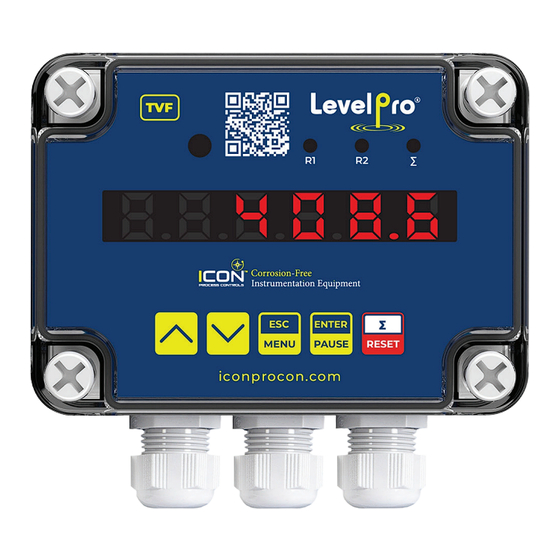
- Page 1 — TVF Series ® Flow Display | Controller | Batcher Quick Start Manual Read the user's manual carefully before starting to use the unit. Producer reserves the right to implement changes without prior notice. 24-0293 © Icon Process Controls Ltd.
-
Page 2: Symbol Explanation
Communication RS485 Voltage 24VDC Passive current output * 4-20mA | (Operating Range Max. 2.8 - 24mA) Performance Accuracy 0.1% @ 25°C One Digit Temperatures Operating Temperature -40 - 158°F | -40 - 70°C *Optional 24-0293 © Icon Process Controls Ltd. -
Page 3: Front Panel Description
Symbol used in the manual : [ ] [ ] Functions: • Change of the present menu • Modification of the parameter value • Switching of the display between relay thresholds and number of batches counter. 24-0293 © Icon Process Controls Ltd. -
Page 4: Wiring Diagram
For this reason, an external time-delay cut-out fuse with a small nominal current value must be used (recommended bipolar, max. 2A) and a power supply circuit breaker located near the unit. 24-0293 © Icon Process Controls Ltd. - Page 5 (typically capacitor 47nF/ min. 250VAC in series with 100R/5W resistor), connected in parallel to relay terminals or (better) directly on the load. Suppression Circuit Connection Figure: Examples of Suppression Circuit Connection a) To Stepper Relay Terminals b) To the Inductive Load (Motor) 24-0293 © Icon Process Controls Ltd.
- Page 6 Current Output Connection Using Internal Power Supply Figure: Example of current output connection using internal power supply Current Output Connection Using External Power Supply Figure: Example of current output connection using external power supply 24-0293 © Icon Process Controls Ltd.
- Page 7 Brown +VDC Black Pulse Jumper Wire Jump 13 & 8 TKW Series : 4-20mA Output TVF Terminal Wire Color Description (option) (option) RS - 485 Blue -VDC 17 16 15 Brown +VDC Black White 24-0293 © Icon Process Controls Ltd.
- Page 8 Jump 13 & 8 TIM Series : 4-20mA Output TVF Terminal Wire Color Description (option) (option) RS - 485 4-20mA (+) Blue -VDC 17 16 15 13 12 Brown +VDC Yellow 4-20mA (-) Grey 24-0293 © Icon Process Controls Ltd.
- Page 9 2 – Pulse Output ® TVF Terminal Wire Color Description (option) (option) Pulse Input RS - 485 Blue -VDC 17 16 15 12 11 Brown +VDC Black Pulse Jumper Wire Jump 13 & 8 24-0293 © Icon Process Controls Ltd.
- Page 10 Eg: To display flow in GPM, Enter K Factor corresponding to GPM. Save Value ▶ Save Selection ENTER PAUSE K Factor ▶ PULSEL MENU Input ▶ Input Menu MENU ▶ Main Display ▶ Main Display 24-0293 © Icon Process Controls Ltd.
-
Page 11: Programming Relays
Enter SET POINT 1 Value Press ENTER to advance to next digit �� ENTER PAUSE PAUSE 2 Sec. Save ▶ Save Value ENTER PAUSE Set Point 1 ▶ SET POINT 1 24-0293 © Icon Process Controls Ltd. - Page 12 Save Value ENTER PAUSE Hysterisis ▶ Hysterisis Menu Mode ▶ MODE Menu ENTER PAUSE On | Off | In | Out ▶ ▶ Press Select On | OFF | In | Out ENTER PAUSE 24-0293 © Icon Process Controls Ltd.
- Page 13 ® Flow Display | Controller | Batcher STEPS DISPLAY OPERATION Save ▶ Save Selection ENTER PAUSE Mode ▶ Mode Menu MENU Relay 1 ▶ Relay 1 Menu MENU Main Display ▶ Main Display ▶ 24-0293 © Icon Process Controls Ltd.
- Page 14 ∑/RESET button. Kind of displayed value is signalised by " ∑" LED. ENTER to start batching ∑ LED ON : Totalizer | ∑ LED OFF: Flow Rate | ∑ LED Pulsing: Batching PAUSE 24-0293 © Icon Process Controls Ltd.
- Page 15 Save Selection ENTER PAUSE Output Mode ▶ Select OUTPUT MODE Source ▶ SOURCE Menu ENTER PAUSE FLo | bAt | tot ▶ Press Select FLo (Flow) ENTER PAUSE Save ▶ Save Selection ENTER PAUSE 24-0293 © Icon Process Controls Ltd.
- Page 16 ENTER to advance to next digit �� ENTER PAUSE PAUSE 2 Sec. Save ▶ Save Value ENTER PAUSE 20mA ▶ 20mA (High value) MENU Output ▶ Output Menu MENU Main Display ▶ Main Display 24-0293 © Icon Process Controls Ltd.
- Page 17 | on ▶ Press Select on ENTER PAUSE Save ▶ Save Selection ENTER PAUSE Mode Clear ▶ Mode Clear MENU Batch Settings ▶ Batch Menu MENU Main Display ▶ Main Display ∑ RESET 24-0293 © Icon Process Controls Ltd.
- Page 18 Relay 1 ▶ Relay 1 Settings Totalizer Menu ▶ TOTALIZER Menu ENTER PAUSE Totalizer Resolution ▶ BATCH RESOLUTION Mode Clear ▶ MODE CLEAR ENTER PAUSE oFF | on ▶ Press Select on ENTER PAUSE 24-0293 © Icon Process Controls Ltd.
- Page 19 ∑" LED. �� ∑ ∑ LED ON : Totalizer | ∑ LED OFF: Flow Rate | ∑ LED Pulsing: Batching RESET 3 Sec. Clear ▶ Clear Totalizer ENTER PAUSE Main Display ▶ Main Display 24-0293 © Icon Process Controls Ltd.
- Page 20 Save Selection ENTER PAUSE Flow Precision ▶ Flow Precision MENU Flow Menu ▶ Flow Menu MENU Main Display ▶ Main Display To change decimal points for Batch | Totalizer, select Batch | Totalizer Menu 24-0293 © Icon Process Controls Ltd.
-
Page 21: Warranty, Returns And Limitations
Icon Process Controls Ltd for a period of one year from the date of sale of such products. Icon Process Controls Ltd obligation under this warranty is solely...


Need help?
Do you have a question about the LevelPro TVF Series and is the answer not in the manual?
Questions and answers