Testboy TB 312 Manual
Hide thumbs
Also See for TB 312:
- Operating instructions manual (56 pages) ,
- Operating instructions manual (219 pages)

Related Manuals for Testboy TB 312


Summary of Contents for Testboy TB 312
-
Page 1: Table Of Contents
DC current measurement / A= AC current measurement / A~ Capacitance measurement / F* Resistance measurement / Ω Diode test Continuity test Frequency Duty cycle Relative value measurement Maintenance Cleaning Changing the batteries Changing the fuse PC software Technical data ® Testboy TB 312... -
Page 2: Notes
Measuring instruments and their accessories are not toys, and must be kept out of the reach of children! In industrial facilities, the accident prevention regulations for electrical systems and equipment, established by the em- ployer's liability insurance association, must be observed. ® Testboy TB 312... - Page 3 Read the instructions completely before beginning the initial commissioning. This instrument is CE-approved and thus fulfils the required guidelines. All rights reserved to alter specifications without prior notice © Testboy GmbH, Germany. ® Testboy TB 312...
-
Page 4: Safety Notes
Objects are also at risk (e.g. damage to the instrument). WARNING An electric shock can result in death or serious personal injury, and also functional damage to objects (e.g. damage to the in- strument). ® Testboy TB 312... - Page 5 All rights reserved with regard to changes, printing mistakes and errors. Disposal Dear Testboy customer: purchasing our product gives you the option of returning the instrument to suitable collection points for waste electrical equipment at the end of its lifespan.
- Page 6 Certificate of quality All activities and processes carried out within Testboy GmbH relating to quality are monitored permanently within the framework of a Quality Management System. Fur- thermore, Testboy GmbH confirms that the testing equipment and instruments used during the calibration process are subject to a permanent inspection process.
-
Page 7: Operation
Operating instructions PC software (CD) USB cable Safety precautions The TB 312 left the factory with its safety features in perfect working order. In order to maintain this condition, the user must observe the safety notes contained in this manual. Caution! - Page 8 Measurement category CAT III Measurements on building installations: fixed consumer units, distributor connection, equipment fitted permanently to the distributor Measurement category CAT IV Measurements at the source of the low voltage installation: meters, primary surge pro- tection, mains connection. ® Testboy TB 312...
-
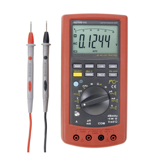
Page 9: Switches, Buttons And Jacks Description
(11) REL button Switch-over to relative value display (12) HOLD button Measured value storage (13) LIGHT button Backlighting (14) ~ HZ button Frequency measurement during voltage and cur- rent measurement (15) LCD display See below ® Testboy TB 312... -
Page 10: Display
Measured value recording MAX maximum, MAX-MIN MIN minimum, MAX-MIN differentiated value Automatic measuring range selection AUTO MANUAL Manual measuring range selection Measured value display 5, 50, 500 and 1000, 51000 5000, etc. Battery icon indicating low battery Relative measurement ® Testboy TB 312... - Page 11 Pause indicator when measuring capacitances of 50 μF - 5000 μF in the automatic measuring Please Wait … range, in order to maintain accuracy until the capacitor has been completely discharged Analogue bargraph display USB connection PCLINK Measured value display ® Testboy TB 312...
-
Page 12: Dc Voltage Measurement / V
± 0.03 % of meas. val.+ 6 digits 500 V 10 mV 1000 V 0.1 V -Input resistance: 10 MΩ. -Max. input voltage: 1000 V DC. Press the SELECT button to switch between DC, AC and AC+DC measurement methods. ® Testboy TB 312... -
Page 13: Ac Voltage Measurement / V
Accuracy specified only valid for 10 % to 100 % of the measuring range. -Input resistance: 10 MΩ. -Max. input voltage: 1000 V AC RMS, frequency range: 40 Hz- 20 kHz. Press the SELECT button to switch between the AC and dBm measuring range. ® Testboy TB 312... -
Page 14: Dc Current Measurement / A
* Following measurement, which should take a max. 10 seconds, allow the instrument to cool down for 15 minutes to protect against overheating. Press the SELECT button to switch between DC, AC and AC+DC measure- ment methods. ® Testboy TB 312... -
Page 15: Ac Current Measurement / A
* Following measurement, which should take a max. 10 seconds, allow the instrument to cool down for 15 minutes to protect against overheating. Press the SELECT button to switch between DC, AC and AC+DC measurement methods. ® Testboy TB 312... -
Page 16: Capacitance Measurement / F
500 kΩ 10 Ω 5 MΩ 100 Ω ± 0.1 % + 10 digits 50 MΩ 1 kΩ ± 0.5 % + 10 digits Input impedance: 10 MΩ, test voltage: 3 V, test current: 2 mA. ® Testboy TB 312... -
Page 17: Diode Test
V / mV / Ω jack. Connect test leads to the test circuit. A signal is emitted if a resistance under 60 Ω is measured. Important: Ensure isolation from the power supply and discharge capacitors in the circuit to be measured. Measuring range Function ◦ The integrated buzzer signals continuity of up to 60 Ω ® Testboy TB 312... -
Page 18: Frequency
Press the “REL” button to enable the relative value measurement method. Pressing the button retains the last measured or displayed value and deducts the subsequent value. The “REL” button can also be used to compensate for test lead resistance. ® Testboy TB 312... -
Page 19: Maintenance
(F 10 A / 1000 V or F 500 mA / 1000 V fuse). Replace the protective cap and retighten the screws of the battery compartment. Only use fuses with the values specified! ® Testboy TB 312... -
Page 20: Pc Software
Open up the contents of the CD in your PC's Explorer and run the Setup.exe. The following drop-down menu appears: Click on the relevant button for the language. After unpacking the installation files, the InstallShield Wizard appears: ® Testboy TB 312... - Page 21 Click on “Next”, select the installation directory and click again on “Next” and then on “Install”, and once installation is complete click on “Finish”: Under Programme/Multimeter click on Multimeter.exe or double click on the Multimeter.exe icon on the desktop and the main window appears: ® Testboy TB 312...
- Page 22 XY plot beneath it, and on the right-hand side the data is transferred to a list that you can then easily save, transfer to EXCEL or print. ® Testboy TB 312...
- Page 23 You can change the time base (X-axis) by using the top arrows, and the Y-axis by using the side arrows. Clicking on “Print” sends the contents of the current display to the printer. Exit the programme by closing the main window. ® Testboy TB 312...
-
Page 24: Technical Data
0 °C to 50 °C RH < 80 % Storage temperature -20 °C to 60 °C RH < 80 % Dimensions 210 x 105 x 45 mm Weight 560 g incl. battery Category CAT III 1000 V Interface USB, optical coupling ® Testboy TB 312...
Need help?
Do you have a question about the TB 312 and is the answer not in the manual?
Questions and answers