Table of Contents
Advertisement
Quick Links
Advertisement
Table of Contents

Related Manuals for Spirax Sarco SV81H


Summary of Contents for Spirax Sarco SV81H
- Page 1 1.753.000.079 IM-D345-01 BR Rev.01 SV81H Safety and Relif Valves Installation and Maintenance Guide 1. Warranty 2. General Safety Information 3. Introduction 4. Terms and Definitions 5. Handling and Storage 6. Installation 7. Maintenance and Testing 8. Trouble Shooting IM-D345-01 BR Rev. 01...
-
Page 2: Warranty
Spirax Sarco only obligation with Warranty is to repair or replace any product that we consider defective. Spirax Sarco reserves the right to inspect the product in customer installations or request the return of the product with freight prepaid by the buyer. -
Page 3: General Safety Information
Tools and consumables Before starting work ensure that you have suitable tools and/or consumables available. Use only genuine Spirax Sarco replacement parts. Protective clothing Consider whether any protective clothing required by yourself and / or others in the vicinity to protect against the hazards of, for example, chemicals, high / low temperature, noise, falling objects, and dangers to eyes and face. -
Page 4: Additional Information
Unless otherwise stated in the Installation and Maintenance Instructions, this product is recyclable and no ecological hazard is anticipated with its disposal providing due care is taken. Additional information Additional information and support are available worldwide at any Spirax Sarco service center. IM-D345-01 BR Rev. 01... - Page 5 Item Descrição Body (Base) Disc O'Ring Retainer Lockscrew Disc Holder Guide Gasket Guide Spindle Spring Washer Spring Bonnet Adjusting Screw Adjusting Screw Locknut Cap Gasket Disc Lever Screw Lever Bushing O'Ring Washer Rivet Cotter Pin Gasket Sealing Plug Gasket Sealing Plug Nameplate Seal Test GAG...
-
Page 6: Terms And Definitions
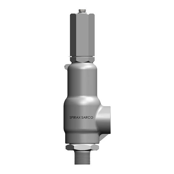
3. Introduction Safety Relief Valves SV81H are designed to meet the requirements of ASME Code Section VIII. They may be used for various media such as air, gases, process steam, liquid and hydrocarbons, it can operate as a safety or relief valve, depending on our application. - Page 7 4.8 Relief Pressure The pressure increase over the set pressure of the relieving device. Overpressure is expressed in pressure units or as a percentage of set pressure. 4.9 Overpressure A pressure increase over the set pressure of a pressure relief valve, usually expressed as a percentage of set pressure.
-
Page 8: Handling And Storage
4.17 Simmer The audible or visible escape of fluid between the seat and disk at an inlet static pressure below the popping pressure and at no measurable capacity. It applies to safety or safety relief valves on compressiblefluid service. 4.18 Chatter Abnormal rapid reciprocating motion of the movable parts of a pressure relief valve in which the disk contacts the seat,causing serious damage to the valve. - Page 9 • The valve should not be bumped or dropped during installation. If the valve is dropped, an inspection for damage should be made, and the set pressure of the valve rechecked. • Make sure that threaded connections, gaskets and connection’s studs are in compliance with specifications of the pipeline.
- Page 10 • Install discharge piping using the same procedures used in the valve installation. • Prior to completing the installation, a visual check should be made to ensure that the valve lifting lever is free to operate. • For valves with test lever, before finishing the installation, check visually if this can be operated freely.
- Page 11 • A Safety and Relief Valves must be installed in upright standing position (+ / - 1) directly on the protected equipment in a pipe with nominal diameter equal or greater than valves diameter, and no longer than the face-to-face dimension of a standard “T” of the applicable pressure class. Sharp edges must be avoided in this pipe section (Figure 03).
- Page 12 • To reduce the effects of excessive turbulence at the inlet of Safety Relief Valves, the following recommendations should be observed (Figure 04): Figure 04 • Safety valves should be installed at least eight to ten pipe diameters downstream from any bend in a process line.
-
Page 13: Outlet Piping
/ or piping. Spirax Sarco can provide this information only as technical assistance but assumes no liability for the calculations. • External loads resulting from support systems and poorly designed piping may be the cause of excessive stresses and distortion in the valve and inlet pipe. The accumulation of stress may cause the valve to malfunction or leak. -
Page 14: Maintenance And Testing
• SV81H series valves can be easily disassembled for inspection, maintenance or parts repla- cement. • SV81H series valves are designed to meet ASME Section VIII requirements for pressure relief valves having non adjustable blowdown (4.12), on all types of media. No blowdown adjustment required when setting or testing the valve. - Page 15 7.1 Disassembly 7.1.1 Remove the cap (29), including the lever system if present. 7.1.2 Remove cap gasket (26). 7.1.3 Note the dimension A, as shown in Figure 06, this information will be necessary to position the adjusting screw (24) when reassembling the valve. Figure 06 7.1.4 Loosen the lock nut (25) and turn the adjusting screw (24) counterclockwise to fully...
- Page 16 7.2 Cleaning The parts should be cleaned using sandpaper and a suitable solvent. During the cleaning process special attention must be paid to the seating surfaces, guided surfaces and threads. Remove any encrustations from the Bonnet (22) by scraping, wire brushing or if necessary, abrasive jets. It is not recommended to use abrasive jet for cleaning the internal parts of the valve.
- Page 17 7.3.2 Disc (09) Look for cuts, nicks or other damage on the seating surface. Check the disc for defects such as cracks (w/ dye penetrant) and/or severe corrosion. Make sure that the outside diameter is not egged and the surface is smooth not showing marks or galled. The disc may be re-machined,If necessary, until the C dimension (Figure 08) is reduced to the minimum indicated in Table 03.
- Page 18 7.4 Lapping SV81H series valves have its seating surfaces (nozzle and disc) lapped in an automatic lapping machine, which ensures the best tightness characteristics. In maintenance services, where de lapping machine is not available, a cast iron block or another perfectly flat surface (e.g. glass) can be used, performing lapping according to the conventional method (Figure 09).
- Page 19 For lapping, it is recommended the following diamond compounds: Micron Size Lapping Phase 20 - 40 Micra Initial Thinning 10 - 20 Micra Quick Thinning and Polishing 6 - 12 Micra Fine Polishing 3 - 6 Micra Extra fine Polishing Table 04 7.5 Assembly SV80H valves can be easily reassembled, without the need of any special tools.
- Page 20 Although the valve can be set on the service installation, it is recommended to set the valve and check seat tightness on a test bench. Any spring replacement shall be in accordance with current Spirax Sarco guidelines. 7.6 Bench Testing and Setting 7.6.1...
- Page 21 7.6.3 The Safety and Relief Valves bench testing procedure shall be in accordance with API Standard 527 STD and ASME Seç. VIII - UG 136 (d) (4) for the marked fluid. 7.6.4 Valves shall be tested by type as fallows: •...
-
Page 22: Hydrostatic Testing
7.6.11 Check the seat tightness according to API STD 527 standard. 7.6.12 Install cap (29) and lever assembly, if present. 7.6.13 Use the backpressure value (C/ P) indicated on the identification plate (Figure 12), when not indicated (sealing bellows) use of 1.5 bar(g). Check the gasket tightness for 2 minutes after application of pressure. -
Page 23: Troubleshooting
8. Trouble Shooting IM-D345-01 BR Rev. 01... - Page 24 Notes IM-D345-01 BR Rev. 01...
- Page 25 Sales Branches Porto Alegre Salvador Av. Inconfidência, 71 sala 2 - Centro Rua André Luiz Ribeiro da Fonte, 24 CEP: 92020-320 Salas 202/203 Canoas - RS Vilas do Atlântico Fone: (051) 3342-5577 CEP: 42700-000 E-mail: filial.portoalegre@br.spiraxsarco.com Lauro de Freitas - BA Fone: (71) 3379-7701 Belo Horizonte email: filial.salvador@br.spiraxsarco.com...
Need help?
Do you have a question about the SV81H and is the answer not in the manual?
Questions and answers