Table of Contents
Advertisement
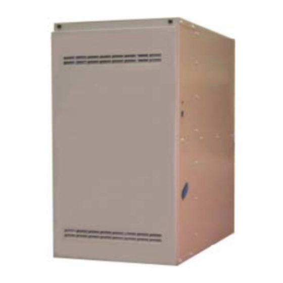
INSTALLATION MANUAL
HIGH EFFICIENCY
CLAM TUBE HEAT EXCHANGER SERIES
MODELS: G8C/GF8
(Single Stage Multi-Position)
50 - 150 MBH INPUT
(14.65 - 44.00 KW) INPUT
SAFETY . . . . . . . . . . . . . . . . . . . . . . . . . . . . . . . . . . . . . . . . . . . . . . . . 1
DUCTWORK . . . . . . . . . . . . . . . . . . . . . . . . . . . . . . . . . . . . . . . . . . . . 4
FILTERS . . . . . . . . . . . . . . . . . . . . . . . . . . . . . . . . . . . . . . . . . . . . . . . 9
GAS PIPING . . . . . . . . . . . . . . . . . . . . . . . . . . . . . . . . . . . . . . . . . . . 11
ELECTRICAL POWER . . . . . . . . . . . . . . . . . . . . . . . . . . . . . . . . . . . 13
Upflow/Horizontal Configuration . . . . . . . . . . . . . . . . . . . . . . . . . . . . . . 5
Downflow/Horizontal Configuration . . . . . . . . . . . . . . . . . . . . . . . . . . . 5
Vent Blower . . . . . . . . . . . . . . . . . . . . . . . . . . . . . . . . . . . . . . . . . . . . . 5
Top Cap . . . . . . . . . . . . . . . . . . . . . . . . . . . . . . . . . . . . . . . . . . . . . . . . 6
Dimensions . . . . . . . . . . . . . . . . . . . . . . . . . . . . . . . . . . . . . . . . . . . . . 7
Combustible Floor Base Accessory . . . . . . . . . . . . . . . . . . . . . . . . . . . 8
Typical Attic Installation . . . . . . . . . . . . . . . . . . . . . . . . . . . . . . . . . . . . 9
Typical Suspended Furnace / Crawl Space Installation . . . . . . . . . . . . 9
Side Return Cutout Markings . . . . . . . . . . . . . . . . . . . . . . . . . . . . . . . 10
Horizontal Mount and Filter . . . . . . . . . . . . . . . . . . . . . . . . . . . . . . . . 10
Downflow Filter . . . . . . . . . . . . . . . . . . . . . . . . . . . . . . . . . . . . . . . . . . 10
Return Filter Grill and Return Duct Installation . . . . . . . . . . . . . . . . . . 11
Gas Valve . . . . . . . . . . . . . . . . . . . . . . . . . . . . . . . . . . . . . . . . . . . . . . 11
Upflow Configuration (50-125 MBH Model Only) . . . . . . . . . . . . . . . . 11
Downflow Configuration (50-125 MBH Model Only) . . . . . . . . . . . . . 12
Upflow/Horizontal Configuration (150 MBH Model Only) . . . . . . . . . . 12
Gas Piping . . . . . . . . . . . . . . . . . . . . . . . . . . . . . . . . . . . . . . . . . . . . . 12
Electrical Wiring - Upflow Position . . . . . . . . . . . . . . . . . . . . . . . . . . . 13
Single Stage Heat Thermostat Connections . . . . . . . . . . . . . . . . . . . 14
Accessory Connections . . . . . . . . . . . . . . . . . . . . . . . . . . . . . . . . . . . 14
Unit Clearances to Combustibles . . . . . . . . . . . . . . . . . . . . . . . . . . . . . 4
Minimum Duct Sizing For Proper Airflow . . . . . . . . . . . . . . . . . . . . . . . 6
External Static Pressure Range . . . . . . . . . . . . . . . . . . . . . . . . . . . . . . 6
Cabinet and Duct Dimensions . . . . . . . . . . . . . . . . . . . . . . . . . . . . . . . 7
Filter Sizes - Upflow . . . . . . . . . . . . . . . . . . . . . . . . . . . . . . . . . . . . . . 10
High Altitude Conversion . . . . . . . . . . . . . . . . . . . . . . . . . . . . . . . . . . 13
Ratings & Physical / Electrical Data - Upflow Models . . . . . . . . . . . . 13
Roof Pitch . . . . . . . . . . . . . . . . . . . . . . . . . . . . . . . . . . . . . . . . . . . . . . 16
Horizontal Sidewall Venting Clearances . . . . . . . . . . . . . . . . . . . . . . 17
SECTION I: SAFETY
This is a safety alert symbol. When you see this symbol on
labels or in manuals, be alert to the potential for personal
injury.
Understand and pay particular attention to the signal words DANGER,
WARNING, or CAUTION.
DANGER indicates an imminently hazardous situation, which, if not
avoided, will result in death or serious injury.
WARNING indicates a potentially hazardous situation, which, if not
avoided, could result in death or serious injury.
CAUTION indicates a potentially hazardous situation, which, if not
avoided may result in minor or moderate injury. It is also used to
alert against unsafe practices and hazards involving only property dam-
age.
LIST OF SECTIONS
TWINNING AND STAGING . . . . . . . . . . . . . . . . . . . . . . . . . . . . . . . .14
VENT/COMBUSTION AIR SYSTEM . . . . . . . . . . . . . . . . . . . . . . . . .16
SAFETY CONTROLS . . . . . . . . . . . . . . . . . . . . . . . . . . . . . . . . . . . .21
START-UP AND ADJUSTMENTS . . . . . . . . . . . . . . . . . . . . . . . . . . .21
WIRING DIAGRAM . . . . . . . . . . . . . . . . . . . . . . . . . . . . . . . . . . . . . .29
LIST OF FIGURES
Typical Twinned Furnace Application . . . . . . . . . . . . . . . . . . . . . . . . .14
Single Stage Twinning Wiring Diagram . . . . . . . . . . . . . . . . . . . . . . .15
Two-Stage Twinning Wiring Diagram . . . . . . . . . . . . . . . . . . . . . . . . .15
Vent Termination . . . . . . . . . . . . . . . . . . . . . . . . . . . . . . . . . . . . . . . .16
Vent Termination . . . . . . . . . . . . . . . . . . . . . . . . . . . . . . . . . . . . . . . .16
Alternate Air Intake, Air Outlet and Chimney Connections . . . . . . . . .16
Air Inlet, Outlet and Chimney Connections . . . . . . . . . . . . . . . . . . . . .17
Typical Sidewall Vent Application . . . . . . . . . . . . . . . . . . . . . . . . . . . .17
Typical Sidewall Vent and Termination Configuration . . . . . . . . . . . .17
Typical Chimney Connections . . . . . . . . . . . . . . . . . . . . . . . . . . . . . .17
Horizontal Air Inlet, Outlet and Chimney Connections . . . . . . . . . . . .17
Home Layout . . . . . . . . . . . . . . . . . . . . . . . . . . . . . . . . . . . . . . . . . . .18
Casing to the Burner Box . . . . . . . . . . . . . . . . . . . . . . . . . . . . . . . . . .19
Outside and Ambient Combustion Air . . . . . . . . . . . . . . . . . . . . . . . . .20
Pressure Switch Tubing Routing . . . . . . . . . . . . . . . . . . . . . . . . . . . .21
Gas Valve . . . . . . . . . . . . . . . . . . . . . . . . . . . . . . . . . . . . . . . . . . . . . .24
Reading Gas Pressure . . . . . . . . . . . . . . . . . . . . . . . . . . . . . . . . . . . .24
Typical Heat/Cool Speed Tap Connections . . . . . . . . . . . . . . . . . . . .25
Wiring Diagram . . . . . . . . . . . . . . . . . . . . . . . . . . . . . . . . . . . . . . . . . .29
LIST OF TABLES
Estimated Free Area . . . . . . . . . . . . . . . . . . . . . . . . . . . . . . . . . . . . . .19
Free Area . . . . . . . . . . . . . . . . . . . . . . . . . . . . . . . . . . . . . . . . . . . . . .19
Unconfined Space Minimum Area in Square Inches . . . . . . . . . . . . .19
Field Installed Accessories - Non Electrical . . . . . . . . . . . . . . . . . . . .22
Inlet Gas Pressure Range . . . . . . . . . . . . . . . . . . . . . . . . . . . . . . . . .24
Nominal Manifold Pressure . . . . . . . . . . . . . . . . . . . . . . . . . . . . . . . . .24
Filter Performance - Pressure Drop Inches W.C. and (kPa) . . . . . . . .26
Blower Performance - CFM . . . . . . . . . . . . . . . . . . . . . . . . . . . . . . . .27
Improper installation may create a condition where the operation of
the product could cause personal injury or property damage.
Improper installation, adjustment, alteration, service or mainte-
nance can cause injury or property damage. Refer to this manual
for assistance or for additional information, consult a qualified con-
tractor, installer or service agency.
This product must be installed in strict compliance with the installa-
tion instructions and any applicable local, state, and national codes
including, but not limited to building, electrical, and mechanical
codes.
EFFICIENCY
RATING
CERTIFIED
ISO 9001
Certified Quality
Management System
269326-UIM-A-1106
Advertisement
Table of Contents

Related Manuals for York GF8


Summary of Contents for York GF8
-
Page 1: Table Of Contents
INSTALLATION MANUAL HIGH EFFICIENCY EFFICIENCY RATING CERTIFIED CLAM TUBE HEAT EXCHANGER SERIES MODELS: G8C/GF8 ISO 9001 (Single Stage Multi-Position) Certified Quality Management System 50 - 150 MBH INPUT (14.65 - 44.00 KW) INPUT LIST OF SECTIONS SAFETY ..........1 TWINNING AND STAGING . -
Page 2: Safety
269326-UIM-A-1106 SPECIFIC SAFETY RULES AND PRECAUTIONS • Provide clearances from combustible materials as listed under Clearances to Combustibles. Only Natural gas or Propane (LP) gas are approved for use with • Provide clearances for servicing ensuring that service access is this furnace. - Page 3 269326-UIM-A-1106 INSPECTION As soon as a unit is received, it should be inspected for possible dam- age during transit. If damage is evident, the extent of the damage The furnace area must not be used as a broom closet or for any should be noted on the carrier’s freight bill.
-
Page 4: Ductwork
269326-UIM-A-1106 Installation in a residential garage: A gas-fired furnace for installation in a residential garage must be installed so the burner(s) and the ignition source are located not less than (18) inches (46 cm) above the floor, and the furnace must be Downflow furnaces for installation on combustible flooring only when installed on the accessory combustible floor base on wood located or protected to avoid physical damage by vehicles. -
Page 5: Upflow/Horizontal Configuration
269326-UIM-A-1106 TO CONVERT FROM DOWNFLOW TO UPFLOW CONFIGURATION (50-125 MBH Models) Lay the furnace on its back. Remove the front door. Remove the seven sheet metal screws that are used to fasten the top cap to the casing. Remove the top cap and save the screws. Remove the four sheet metal screws that are used to fasten the bottom cap to the casing. -
Page 6: Top Cap
269326-UIM-A-1106 12. Install the two extra machine screws in the two open holes in the Take 8 x 14, which equals 112 sq.in. X 2, which equals 224 square front of the vent pan. See Figure 2. inch then go to round duct size located in Table 2. 13. -
Page 7: Dimensions
269326-UIM-A-1106 TABLES 2 and 3 are to be used as a guide only to help the installer determine if the duct sizes are large enough to obtain the proper air flow (CFM) through the furnace. TABLES 2 and 3 ARE NOT to be used to design ductwork for the building where the furnace is being installed. -
Page 8: Combustible Floor Base Accessory
269326-UIM-A-1106 RESIDENTIAL AND NON HUD MODULAR HOME UPFLOW RETURN PLENUM CONNECTION DOWNFLOW Return air may enter the furnace through the side(s) or bottom depend- FURNACE ing on the type of application. Return air may not be connected into the WARM AIR PLENUM rear panel of the unit. -
Page 9: Filters
269326-UIM-A-1106 ATTIC INSTALLATION Horizontal Installations With a Cooling Coil Cabinet The furnace should be installed with coil cabinet part number specifi- LINE CONNECT ONLY PERMISSIBLE BETWEEN cally intended for Horizontal application. If a matching cooling coil is LINES FORMED BY THE INTERSECTION OF used, it may be placed directly on the furnace outlet and sealed to pre- FURNACE TOP AND TWO SIDES AND BUILDING JOISTS, STUDS, OR FRAMING... -
Page 10: Side Return Cutout Markings
269326-UIM-A-1106 TABLE 5: Filter Sizes - Upflow UPFLOW Side Bottom/End Input Air Flow Cabinet Return Return Size /min 14.7 1200 34.0 25 x 16 64 x 41 25 x 16 64 x 41 22.0 1200 34.0 25 x 16 64 x 41 25 x 16 64 x 41 22.0... -
Page 11: Gas Piping
269326-UIM-A-1106 Downflow Filters Downflow furnaces typically are installed with the filters located above the furnace, extending into the return air plenum or duct. Any branch For applications requiring more than 1800 CFM, it is required to use duct (rectangular or round duct) attached to the plenum must attach to both side returns or one side plus the bottom return. -
Page 12: Downflow Configuration (50-125 Mbh Model Only)
269326-UIM-A-1106 EXTERNAL MANUAL SHUTOFF VALVE VENT FURNACE TO GAS TO GAS VENT PIPE CONTROL SUPPLY SUPPLY TRANSITION BLOWER PIPE DOOR SWITCH 3” DIAMETER VENT PIPE GROUNDED JOINT UNION ROLL-OUT DRIP MAY BE INSTALLED SHUT-OFF SWITCHES INSIDE OR OUTSIDE UNIT. VALVE BURNERS ROLL-OUT FIGURE 17: Gas Piping... -
Page 13: Electrical Power
269326-UIM-A-1106 TABLE 6: High Altitude Conversion Type Orifice at 2,000 ft. 3,000 ft. 4,000 ft. 5,000 ft. 6,000 ft. 7,000 ft. 8,000 ft. 9,000 ft. 10,000 ft. Of Gas Sea Level (610 m) (914 m) (1219 m) (1524 m) (1829 m) (2134 m) (2438 m) (2743 m) -
Page 14: Single Stage Heat Thermostat Connections
269326-UIM-A-1106 CONDENSING ROOM FURNACE UNIT THERMOSTAT CONTROL TO AIR CONDITIONER Before installing the relay and wiring, disconnect electrical power to CONTROLS both furnaces. Failure to cut power could result in electrical shock Y/Y2 or equipment damage. COMMON T’STAT CONNECTION TWINNING DUCT SYSTEM FIGURE 19: Single Stage Heat Thermostat Connections Twinned furnaces must only be applied on a common duct system. -
Page 15: Single Stage Twinning Wiring Diagram
269326-UIM-A-1106 TWINNING STAGING In applications where more heating capacity or more airflow capacity is Single-Wire Twinning needed than what one furnace can deliver, twinning can be used to The control in the furnace has the single-wire twinning feature. With this make two furnaces operate in tandem, using one duct system and one feature, a single wire is connected between the TWIN terminal on one room thermostat. -
Page 16: Roof Pitch
269326-UIM-A-1106 SECTION VII: VENT/COMBUSTION AIR CATEGORY 1 - 450 F. MAX. VENT TEMP. SYSTEM The venting system must be installed in accordance with Section 5.3, Air for Combustion and Ventilation, of the National Fuel Gas Code VENT SAFETY Z223.1/NFPA 54 (latest edition), or Sections 7.2, 7.3 or 7.4 of CSA This Category I, furnace is designed for residential application. -
Page 17: Horizontal Sidewall Venting Clearances
269326-UIM-A-1106 CHIMNEY OR VENT GAS VENT DAMPER VENT PIPE VENTILATION LOUVERS (Each end of attic) FLUE PIPE COVER OPTIONAL SIDEWALL OUTLET VENT SYSTEM (field supplied) BURNER CELLAR ACCESS WALL PANEL INLET AIR DUCT {Ends 1 ft (30 cm) FIGURE 29: Typical Sidewall Vent and Termination Configuration above floor} TABLE 9: Horizontal Sidewall Venting Clearances Horizontal Vent Length Ft. -
Page 18: Home Layout
269326-UIM-A-1106 VENT TERMINAL FIXED AIR SUPPLY CLOSED AREA WHERE TERMINAL IS NOT PERMITTED FIXED CLOSED OPERABLE FIGURE 32: Home Layout Canadian Installations US Installation A. Clearance above grade, veranda, porch, deck, or balcony 12 inches (30 cm) 12 inches (30 cm) 12 inches (30 cm) for models <100,000 B. -
Page 19: Combustion Airflow Path Through The Furnace Casing To The Burner Box
269326-UIM-A-1106 FAN-ASSISTED COMBUSTION SYSTEM Combustion Air Source From Outdoors An appliance equipped with an integral mechanical means to either The blocking effects of louvers, grilles and screens must be given con- draw or force products of combustion through the combustion chamber sideration in calculating free area. -
Page 20: Outside And Ambient Combustion Air
269326-UIM-A-1106 AIR SUPPLY OPENINGS AND DUCTS VENT VENT GABLE VENT 1. An opening may be used in lieu of a duct to provide to provide the outside air supply to an appliance unless otherwise permitted by the authority having VENTILATED ATTIC jurisdiction. -
Page 21: Safety Controls
269326-UIM-A-1106 CARBON MONOXIDE POISONING HAZARD Failure to follow the steps outlined below for each appliance connected to the venting system being placed into operation could result in carbon monoxide poisoning or death. The following steps shall be followed for each appliance connected to the venting system being placed into operation, while all other appliances connected to the venting system are not in operation: 1. -
Page 22: Field Installed Accessories - Non Electrical
269326-UIM-A-1106 TOOLS AND INFORMATION THAT WILL BE After this warm up, the ignition module will energize (open) REQUIRED IN ORDER TO PROPERLY PERFORM THE the main gas valve. FURNACE STARTUP PROCEDURE. After flame is established, the supply air blower will start in about 30 seconds. - Page 23 269326-UIM-A-1106 In the USA use the following formula to calculate the furnace input. For natural gas multiply the heat content of the gas BTU/SCF (or Default 1030 BTU/SCF, times 2 cubic ft. of gas measured at the gas meter, times a barometric pressure and temperature correction factor of 0.960;...
-
Page 24: Gas Valve
269326-UIM-A-1106 IMPORTANT: If gas valve regulator is turned in (clockwise), manifold pressure is increased. If screw is turned out (counterclockwise), mani- fold pressure will decrease. After the manifold pressure has been adjusted, re-calculate the Be sure to relight any gas appliances that were turned off at the furnace input to make sure you have not exceeded the specified start of this input check. -
Page 25: Typical Heat/Cool Speed Tap Connections
269326-UIM-A-1106 ADJUSTMENT OF TEMPERATURE RISE All direct-drive blowers have multi-speed motors. The blower motor speed taps are located in the control box in the blower compartment. Refer to Figure 38, and the unit wiring label to change the blower speed. To use the same speed tap for heating and cooling, the heat ter- minal and cool terminal must be connected using a jumper wire and The temperature rise, or temperature difference between the return connected to the desired motor lead. -
Page 26: Filter Performance - Pressure Drop Inches W.c. And (Kpa)
269326-UIM-A-1106 4 RED FLASHES: This indicates that a primary or auxiliary limit switch NOTE: If a flame is detected the control flashes the LED for 1/8 of a second and then enters a flame stabilization period. has opened its normally closed contacts. With this fault code the control will operate the supply air blower and inducer. -
Page 27: Blower Performance - Cfm
269326-UIM-A-1106 APPLYING FILTER PRESSURE DROP TO Example: For a 75,000 BTUH (21.98 kW) furnace with 2 return open- DETERMINE SYSTEM AIRFLOW ings and operating on high-speed blower, it is found that total system static is 0.38” w.c. To determine the system airflow, complete the follow- To determine the approximate airflow of the unit with a filter in place, fol- ing steps: low the steps below:... - Page 28 269326-UIM-A-1106 TABLE 17: Blower Performance - CFM (Continued) External Static Pressure, Inches WC External Static Pressure (kPa) BTU/H (kW) Cabinet Speed (0.025) (0.050) (0.075) (0.099) (0.124) (0.149) (0.174) (0.199) Input Size CFM CFM CFM CFM CFM CFM CFM CFM m /min m /min m /min m...
-
Page 29: Wiring Diagram
269326-UIM-A-1106 SECTION X: WIRING DIAGRAM FIGURE 39: Wiring Diagram Unitary Products Group... - Page 30 269326-UIM-A-1106 NOTES Unitary Products Group...
- Page 31 269326-UIM-A-1106 NOTES Unitary Products Group...
- Page 32 NOTES Subject to change without notice. Printed in U.S.A. 269326-UIM-A-1106 Copyright © by York International Corp. 2006. All rights reserved. Supersedes: 66832-UIM-E-0806 Unitary 5005 Norman Product York Group Drive 73069...
Need help?
Do you have a question about the GF8 and is the answer not in the manual?
Questions and answers