Advertisement
Quick Links
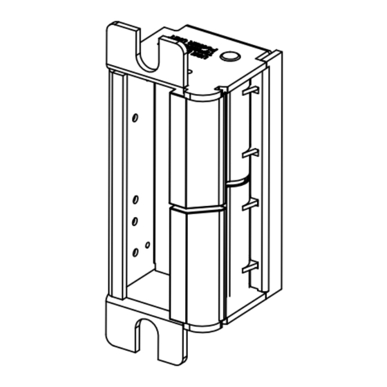
FLUSH TO FRAME
If the 4100DBDL electric strike does not mount flush to the
rabbet of the frame, use the enclosed shims to correct this
condition. There are two ways of mounting the shim; 1)
between the strike mechanism and the faceplate as shown in
figure #2 or 2) between the frame mounting tab and the
strike mechanism as shown on figure #3.
TROUBLESHOOTING THE COMPLETED INSTALLATION:
DO NOT APPLY AN OVER VOLTAGE OF MORE THAN 10%
OVER THE RATED OPERATING VOLTAGE OF THE STRIKE OR
THE SOLENOID WILL BE DAMAGED
SYMPTOM: Electric release is not actuating:
1. Verify proper voltage is present AT THE STRIKE. If voltage is
present, the strike may have been affected during the
installation, or dirt or debris may be preventing proper
operation. Ensure that all moving parts are clean. DO NOT
LUBRICATE THE SOLENOID.
2. If voltage IS NOT present:
· Verify Circuit breaker is on
· Verify voltage at the transformer/power supply output.
· Verify that there are no additional, external switches or
devices which may be interrupting your circuit.
· Check for damaged wiring or bad wire splices.
WIRING DIAGRAMS
+
PUSH
BUTTON
NORMALLY OPEN
-
TO 120V AC LINE
24V DC OR 12V DC TRANSFORMER
For AC use the 12 VDC connectors
For 12 - 24 VAC use 50-60 Hz
+
PUSH
BUTTON
NORMALLY
CLOSED
-
TO 120V AC LINE
24V DC OR 12V DC
TRANSFORMER
Cannot use AC in Fail Safe Configuration
Figure #1
Figure #2
Strike seats below
the rabbet of
Strike
Faceplate
the frame.
Mechanism
Shims
SYMPTOM: Door will not open but strike is working
· First, check to see if the electric strike works properly
while the door is open.
· Check for proper lock-latch engagement
· Check for pressure from the door on the electric strike
by following these steps:
Push the door from the outside, try and relieve the bolt
to latch pressure and actuate the 4100. While the
4100 is unlatched swing the door open. If the door
opens, then the bolt maybe applying pressure to the
latch. Adjust the position of the 4100 to relieve the
pressure.
Possible remedies include:
1. Re-adjust door closer.
2. Remove door silencers.
3. Remove, or trim, weather stripping around the door.
4. Adjust electric strike position if possible.
5. Correct excessive warping of door.
USE THE PROPER
CONNECTOR 12VDC OR 24VDC
ASSEMBLY FOR
THE 4100DBDL STRIKE
PHONE: 203-730-1756
FAIL-SECURE
FAX: 203-730-1781
ELECTRIC STRIKE
2 Parklawn Drive, Suite F
Bethel, CT 06801
email: customerservice@trineonline.com
USE THE PROPER
website: www.trineonline.com
CONNECTOR 12VDC OR 24VDC
ASSEMBLY FOR
THE 4100DBDL STRIKE
V. 17.0411
FAIL-SAFE
ELECTRIC STRIKE
4100DBDL
Figure #3
ELECTRIC
STRIKE
INSTALLATION INSTRUCTIONS
Strike
Mechanism
Shims
1" CAVITY DEPTH
4100DBDL
LEFT HANDED
3 3/8"
1 5/8"
1.005
1.005
1.455
4.865
2.875
4.865
1.455
2.620
0.849
0.790
4
1.240
1.240
TRINE 4100DBDL
Congratulations on the purchase of this quality TRINE security
product. This product has been designed to install easily,
perform reliably, and provide years of trouble free security.
BEFORE PROCEEDING
following list of features. If you have any questions after reading
this document please call TRINE's TECHNICAL SUPPORT (203)
730-1756 EXT. 447, or visit the TRINE Web site at
www.trineonline.com
1 1/4"
The 4100DBDL is WH recognized for:
13/16"
Class A, 3 Hour Single door / frame configuration
- UL10C, Fire Tests of Door Assemblies
- UBC 7-2, Uniform building Code
- CAN4 S104, Standard Method for Fire Tests of Door Assemblies
NFPA 252 -
Issue: 1999/01/01 Standard Methods of Fire Tests of Door Assemblies
NOTE: WH fire listing is void when using fail safe action.
ANSI/BHMA A156.5 - 1992 - 4-7/8" x 1-1/4" Fits
Cutout Specification A115.1 (with Slight Jamb Modification)
4 7/8"
BHMA - Grade 1
4100DBDL
ELECTRICAL CHARACTERISTICS:
4 1/8"
Current
Voltage
3 1/8"
12DC
24DC
12AC
@ 50-60Hz
16AC
@ 50-60Hz
24AC
@ 50-60Hz
NOTE: Volts/Amps for one (1) solenoid.
When removing the connector and using the wires direct;
Red & Blue Wire accepts 12DC & 12-16 AC,
Brown & Blue Wire accepts 24DC.
7/8"
OPERATING TEMP RANGE: -20°C TO +40°C
DO NOT APPLY AN OVER VOLTAGE OF MORE THAN 10%
OVER THE RATED OPERATING VOLTAGE OF THE
1.005
STRIKE OR THE SOLENOID WILL BE DAMAGED.
1.005
1 - (1) 4100DBDL Electric
Strike Mechanism (w/ dual latches)
2 - (4) Faceplates
3 - (2) #12-40 x 1 inch Philips Mounting Screws
4 - (4) Quick Connect Socket &
4.865
4.865
Wire Assembly 12VDC
3.125
3.125
& 24VDC Version
6 - (2) Sealed Crimp
Connectors
7 - (1) Frame Trim Skirt
& (2) Screws
0.865
0.719
2 Parklawn Drive l Suite F l Bethel l CT l 06801
with your installation, please review the
Power
Draw
Consumption
Resistance
.240 A
2.90 W
50 Ω
.114 A
2.74 W
210 Ω
.210 A
2.50 W
50 Ω
.281 A
4.48 W
50 Ω
.420 A
10.08 W
50 Ω
WHAT'S IN THE BOX:
Advertisement

Related Manuals for Trine 4100DBDL


Summary of Contents for Trine 4100DBDL
- Page 1 FLUSH TO FRAME Figure #1 Figure #2 Figure #3 If the 4100DBDL electric strike does not mount flush to the rabbet of the frame, use the enclosed shims to correct this ELECTRIC condition. There are two ways of mounting the shim; 1)
- Page 2 INSTALLING THE 4100DBDL STRIKE: RECOMMENDED PRE-INSTALLATION CHECK: NOTE: The 4100DBDL electric strike has two terminal wires to supply power to two separate solenoids. 1. Determine that the door swings without interfering with jamb or sill; the door must operate properly in USE THE BOTTOM WIRE LEADS FOR THE MORTISE LATCH AND THE TOP order for the system to provide best results.
Need help?
Do you have a question about the 4100DBDL and is the answer not in the manual?
Questions and answers