Table of Contents
Advertisement
Quick Links
USING THE LATCH SPACER SHIMS
The latch spacer shims are used to make adjustments to
minimize the space between the door's inside face and the
door stop or reduce door play. For cylindrical locks aligning to
the vertical center of the strike mount
the shims as shown below.
Mount the shims with the steps
positioned aligned with the top
of the latch like this.
This position will ensure that the cylindrical
lock's auxilliary trigger will function properly.
Auxilliary Trigger
TROUBLESHOOTING THE COMPLETED INSTALLATION:
DO NOT APPLY AN OVER VOLTAGE OF MORE THAN 10%
OVER THE RATED OPERATING VOLTAGE OF THE STRIKE OR
THE SOLENOID WILL BE DAMAGED
SYMPTOM: Electric release is not actuating:
1. Verify proper voltage is present AT THE STRIKE. If voltage is
present, the strike may have been affected during the
installation, or dirt or debris may be preventing proper
operation. Ensure that all moving parts are clean. DO NOT
LUBRICATE THE SOLENOID.
2. If voltage IS NOT present:
· Verify Circuit breaker is on
· Verify voltage at the transformer/power supply output.
· Verify that there are no additional, external switches or
devices which may be interrupting your circuit.
· Check for damaged wiring or bad wire splices.
WIRING DIAGRAMS
+
CONNECTOR 12VDC OR 24VDC
PUSH
BUTTON
NORMALLY OPEN
-
TO 120V AC LINE
24V DC OR 12V DC TRANSFORMER
For AC use the 12 VDC connectors
For 12 - 24 VAC use 50-60 Hz
+
CONNECTOR 12VDC OR 24VDC
PUSH
BUTTON
NORMALLY
CLOSED
-
TO 120V AC LINE
24V DC OR 12V DC
TRANSFORMER
Cannot use AC in Fail Safe Configuration
USING THE LATCH SPACER SHIMS (CONTINUED...)
For locks not aligning to the vertical center of the strike, mount
the shims as shown below. Most if not all mortise locks will
work with the latch shims mounted this way.
Mount the shims with the
steps positioned away from
the top of the latch like this.
Auxilliary
Deadlocking Trigger
SYMPTOM: Door will not open but strike is working
· First, check to see if the electric strike works properly
while the door is open.
· Check for proper lock-latch engagement
· Check for pressure from the door on the electric strike
by following these steps:
Push the door from the outside, try and relieve the bolt
to latch pressure and actuate the 4100. While the
4100 is unlatched swing the door open. If the door
opens, then the bolt maybe applying pressure to the
latch. Adjust the position of the 4100 to relieve the
pressure.
Possible remedies include:
1. Re-adjust door closer.
2. Remove door silencers.
3. Remove, or trim, weather stripping around the door.
4. Adjust electric strike position if possible.
5. Correct excessive warping of door.
4100 OPTIONS:
USE THE PROPER
4100RS - FAIL SAFE CONFIGURATION
ASSEMBLY FOR
THE 4100 STRIKE
4100LB - LATCH BOLT MONITORING
4100RSLB - FAIL SAFE/LATCH
BZ-12 - 12VDC Piezo Buzzer
BZ-24 - 24VDC Piezo Buzzer
FAIL-SECURE
ELECTRIC STRIKE
USE THE PROPER
ASSEMBLY FOR
THE 4100 STRIKE
PHONE: (718) 829-2332
FAX: (718) 829-6405
1440 FERRIS PLACE
BRONX, NY 10461
email: customerservice@trineonline.com
website: www.trineonline.com
FAIL-SAFE
V. 14.0814
ELECTRIC STRIKE
4100
ELECTRIC
STRIKE
INSTALLATION INSTRUCTIONS
FACEPLATE AND OFFSET DIMENSIONS:
BOLT MONITORING
19/32"
4
1 15/32"
MHO
TRINE 4100
THE ONE BOX SOLUTION
FOR CYLINDRICAL AND MORTISE LOCKS
Congratulations on the purchase of this quality TRINE security
product. This product has been designed to install easily,
perform reliably, and provide years of trouble free security.
BEFORE PROCEEDING
following list of features. If you have any questions after reading
this document please call TRINE's TECHNICAL SUPPORT (718)
829-2332 EXT. 447, or visit the TRINE Web site at
www.trineonline.com
The 4100 is WH recognized for:
Class A, 3 Hour Single door / frame configuration
- UL10C, Fire Tests of Door Assemblies
- UBC 7-2, Uniform building Code
- CAN4 S104, Standard Method for Fire Tests of Door Assemblies
NFPA 252 -
Issue: 1999/01/01 Standard Methods of Fire Tests of Door Assemblies
NOTE: WH fire listing is void when using fail safe action.
ANSI/BHMA A156.5 - 1992 - 4-7/8" x 1-1/4" Fits
Cutout Specification A115.1 (with Slight Jamb Modification)
BHMA - Grade 1
4100 ELECTRICAL CHARACTERISTICS:
Voltage
12DC
24DC
12AC
@ 50-60Hz
16AC
@ 50-60Hz
24AC
@ 50-60Hz
CC Faceplate
When removing the connector and using the wires direct;
(centered opening)
OPERATING TEMP RANGE: -20°C TO +40°C
DO NOT APPLY AN OVER VOLTAGE OF MORE THAN 10%
OVER THE RATED OPERATING VOLTAGE OF THE
STRIKE OR THE SOLENOID WILL BE DAMAGED.
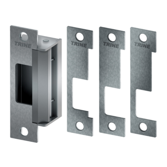
1 - (1) 4100 Electric
Strike Mechanism
2 - (4) Faceplates with Openings (CC, MHO, MMO, MLO)
3 - (2) #12-40 x 1 inch Philips Mounting Screws
4 - (2) #12-40 x 1 inch Torx
5 - (2) Quick Connect Socket &
Wire Assembly 12VDC
& 24VDC Version
6 - (2) Sealed Crimp
Connectors
7 - (2) Latch Spacer
Shims & (2) Mounting Screws
29/32"
1 1/64"
8 - (1) Frame Trim Skirt & (2) Screws
MMO
1 11/32"
MLO
1 11/32"
1440 Ferris Place l Bronx l New York l 10461
with your installation, please review the
Current
Power
Draw
Consumption
Resistance
.240 A
2.90 W
50 Ω
.114 A
2.74 W
210 Ω
.210 A
2.50 W
50 Ω
.281 A
4.48 W
50 Ω
.420 A
10.08 W
50 Ω
Red & Blue Wire accepts 12DC & 12-16 AC,
Brown & Blue Wire accepts 24DC.
WHAT'S IN THE BOX:
®
Security Mounting Screws
Advertisement
Table of Contents

Related Manuals for Trine 4100 Electric Strike


Summary of Contents for Trine 4100 Electric Strike
- Page 1 BEFORE PROCEEDING with your installation, please review the following list of features. If you have any questions after reading this document please call TRINE's TECHNICAL SUPPORT (718) 829-2332 EXT. 447, or visit the TRINE Web site at www.trineonline.com Auxilliary Auxilliary Trigger...
- Page 2 The top terminal is not FLUSH TO FRAME MMO: Mortise Medium Offset (Reference HES ® K faceplate) used. Put electrical tape If the 4100 electric strike does not mount flush to the rabbet of the frame, Quick Connect Baldwin ® , Marks ®...
-
Page 3: What's In The Box
BEFORE proceeding with your installation, please review the 1/4" following list of features. If you have any questions after reading this document please call TRINE's TECHNICAL SUPPORT (718) 829-2332 EXT. 447, or visit the TRINE web site at www.trineonline.com 25/32" WHAT'S IN THE BOX: 1 5/8"... -
Page 4: Frame Preparation
4200 OPTIONS: Metal Frame 4200RS - FAIL SAFE CONFIGURATION 4200LB - LATCH BOLT MONITORING 1 1/4" (coming soon) 4200RSLB - FAIL SAFE/LATCH BOLT MONITORING DIMENSIONS (coming soon) (Included) BZ-12 - 12VDC Piezo Buzzer BZ-24 - 24VDC Piezo Buzzer Aluminum FRAME PREPARATION 5/32"... - Page 5 2. Pull the switched power RECOMMENDED PRE-INSTALLATION CHECK: Quick Connect wires to the door frame. Socket 1. Determine that the door swings without interfering with (Caution: Connect Crimp jamb or sill; the door must operate properly in order for the power ONLY as the last Connector system to provide best results.
-
Page 6: Wiring Diagrams
PREMIUM TRIM SKIRT FOR THE 4200 USING THE LATCH SPACER SHIM The latch spacer shim is used to make an adjustment to USING THE TRIM SKIRT minimize the space between the door's inside face and the door stop, or reduce door play. For cylindrical locks aligning to the The skirt can be used to clean up the vertical center of the strike mount the shim as shown below. - Page 7 (see figure on right). Save the plunger and BLUE diameter) Drill Bit Figure 1 colored spring assembly for future use. Congratulations on the purchase of this quality TRINE CAUTION: TO AVOID ELECTRICAL SHOCK AND INJURIES, - #30 (0.128 inch With the door closed, BEFORE DOING YOUR WIRING, TURN OFF THE POWER FROM security product.
- Page 8 (see figure on right). Save the plunger and BLUE diameter) Drill Bit Figure 1 colored spring assembly for future use. Congratulations on the purchase of this quality TRINE CAUTION: TO AVOID ELECTRICAL SHOCK AND INJURIES, - #30 (0.128 inch With the door closed, BEFORE DOING YOUR WIRING, TURN OFF THE POWER FROM security product.
-
Page 9: Electric Strike
FOR RIM PANIC EXIT DEVICES INSTALLATION INSTRUCTIONS on the wire channel (see figure on right). Save the plunger and BLUE Congratulations on the purchase of this quality TRINE colored spring assembly for future use. 1/4" security product. This product has been designed to 1/2”... -
Page 10: Recommended Tools
RECOMMENDED CHECK OUT THE VIDEO ON USE THE 4850ITL TO QUICKLY TOOLS: SEARCH MARK, TEST, ADJUST, CENTER - 3/32 inch Allen Wrench PUNCH AND SKIP MOST OF “4850ITL” WHAT IS INCLUDED - 3/16 inch Allen Wrench THESE STEPS! IN THE 4850 BOX: more info @ trineonline.com/4850itl.php - 3/4 inch diameter Drill Bit - #7 (0.201 inch... - Page 11 4850LB/4800FLB SPECIFICATION AND INSTRUCTION SHEET P: (203) 730-1756 -- F: (203) 730-1781 www.trineonline.com APPLICATION: TECHNICAL SPECIFICATIONS: • • ® Remote central station notification SHARP Infrared optical sensor • • Local alarm monitoring Normally Open and Normally Closed • contact terminals Triggering video surveillance and •...
-
Page 12: Control Panel
WIRING SCHEMATICS FOR DIFFERENT APPLICATIONS PANEL SIDE WIRING CONTROL SWITCH OR RELAY FRAME SIDE WIRING STRIKE POWER 12VDC POWER OUTPUT WIRE LEADS SUPPLY FOUR WIRE SCHEMATIC UTILIZING CONTROL ONE TRANSFORMER PANEL LB SENSOR POWER This wiring arrangement WIRE LEADS uses the least amount of BLACK - conductors between the RED +... -
Page 13: Standard Features
TRINE TECH SUPPORT (718) 829-2332 EXT. 425, or visit the TRINE Website www.TrineOnline.com. Model Number: 3234 - Fail Secure The TRINE Model #3234, #3234W & Model #3478 are 3234RS - Fail Safe designed for new installation or retrofitting into metal, Model Number: wood and aluminum door frames. -
Page 14: Getting Started
RIGHT HAND OUTSIDE (LH) (RH) powered for extended periods, commonly referred to as CONTINUOUS DUTY. The TRINE LC version of MODEL # 3234, 3234W, #3478, # OUTSIDE LEFT HAND RIGHT HAND 3234-RS, #3234W-RS and #3478-RS can be used for REVERSE BEVEL... -
Page 15: Power Sources
TRINE strike you then add a sounding device as shown in the accompanying have, that the circuitry supplying the voltage is operating wiring diagrams. -
Page 16: Installation Drawings
INSTALLATION DRAWINGS METAL AND WOOD FRAME INSTALLATION The 3478's 4-7/8" x 1-1/4" faceplate requires the least amount of jamb preparation when compared with other electric OPTIONAL 1 1/4" strikes. 1/16" THICK 1 1/4" SHIM 1 1/4" 1 1/4" 3/32" 3/4" 1 1/4"... -
Page 17: Wiring Diagram
INSTALLATION DRAWINGS (Continued) METAL FRAME INSTALLATION The 3234's 2-3/4" x 1-1/4" faceplate requires the least amount of jamb preparation when compared with other electric strikes. 1 1/8" 1 11/16" 1/8" OPTIONAL 5/8" 1 1/8" 1/16" THICK SHIM 1 1/32" 5/8" 5/8"... - Page 18 WIRING DIAGRAM (continued) FIGURE 3 USING AC TRANSFORMER 24V AC OR 12V AC TRANSFORMER PUSH RECTIFIER* BUTTON FAIL-SECURE NORMALLY OPEN ELECTRIC LC100** STRIKE TO 120V AC LINE BLACK * The rectifier can be positioned before of after the push button in the circuit.
- Page 19 8. Install electric release as per attached guidelines. Dark Bronze - US10B 9. Wire electric release as per attached guidelines. Bright Chrome - US26 10. Perform final test of completed installation. Be sure that you have ordered the correct TRINE strike for your application.
-
Page 20: Wire Lengths
#4730/4501 Strike plate. The TRINE MODEL # 3258RS and Model #3458RS For both the TRINE #3258 & #3458 retrofits, these strikes are FAIL-SAFE "CONTINUOUS DUTY" versions may be used designed so that the original mounting tab holes may be for applications where the release must remain UNLOCKED used to secure the electric release into the frame. - Page 21 But too little lock-latch engagement will result in an installation were the door may be easily spread; allowing The TRINE MODEL #5208 (12 VDC) or MODEL # 5209 (24 the locked door to be forced open. VDC) are suitable DC POWER SUPPLIES which are plug-in...
- Page 22 FIGURE 1 USING DC TRANSFORMER PUSH BUTTON NORMALLY OPEN TO 120V AC LINE 24V DC OR 12V DC BLACK TRANSFORMER FAIL-SECURE ELECTRIC ** When wiring the optional buzzer, polarity must be STRIKE observed. Connect the (+ or RED) positive wire to the (+) positive side of the circuit and the (- or BLACK) negative side wire terminal to the negative side of the circuit.
- Page 23 1 9/16" ALUMINUM FRAME INSTALLATION The 3458's 4-5/8" x 1-9/16" full lip steel faceplate requires the 9/16" least amount of jamb preparation when compared with other electric strikes with an auxiliary ramp. The full lip design acts as a trim plate by wrapping around the frame edge. Figure 5 shows the required cutting.
- Page 24 TROUBLESHOOTING THE COMPLETED INSTALLATION: SYMPTOM: Electric release is not actuating: 1. Verify proper voltage is present AT STRIKE. If voltage IS present: the strike may have been damaged during the installation, or dirt or debris may be preventing proper operation. 2.
- Page 26 Instruction Manual AXION SERIES - ELECTRIC STRIKE MODEL EN400, EN400RP TRINE ACCESS TECHNOLOGY 1440 Ferris Place, Bronx, NY 10461-3699 PH: 718-829-2332 -- FX: 718-829-6405 www.trineonline.com PARTS LIST NOTE: Number in parenthesis ( ) indicates part in Parts List. Index No.
-
Page 27: Latch Assembly
DOOR HANDING GUIDE HANDING DETERMINATION 400 LATCH RP LATCH FOR CYLINDRICAL FOR RIM PANIC Door handing is determined by SWAP LATCHES & MORTISE LOCKS DEVICES the position of the hinges, as At 5 (Below) you viewed from the outside of the LATCH ASSEMBLY may switch out the room or building. - Page 28 Door Handing Determination Cont... Page 2 INSTALLATION PROCEDURE: NOTE The position of the Electric Strike in the door - For new or replacement installation in wood For DC operation, to obtain an audible jamb will be the same for a right-handed door or metal jambs.
-
Page 29: Troubleshooting
Check that lockset is compatible with EN series cavity and requirements. If necessary, use other type of lockset electric strike or Electric Strike (refer to Trine Catalog for more information). 3) Latch Spring broken Hold Electric Strike so that wiring faces down and apply pressure to Latch. Verify that Latch releases and that there is sufficient Spring tension to push it to closed positionwhen released. - Page 30 Instruction Manual AXION SERIES - ELECTRIC STRIKE MODEL EN 430/435 TRINE ACCESS TECHNOLOGY 1440 Ferris Place, Bronx, NY 10461-3699 Phone: 718 829-2332 Fax: 718 829-6405 www.trineonline.com PARTS LIST Index No. Name Part Number Latch EN-430/435-LCH NOTE: Number in parenthesis ( ) indicates part in Parts List.
- Page 31 Wiring HANDING DETERMINATION Figure 4. Spring The handing of a door is determined Position of by the position of the hinges, as Latch Electric Strike viewed from the outside of the room, for Left building, office, etc. If the door hinges Handed Door are on the left, the door is termed Tail...
-
Page 32: Installation Procedure
5. Splice Electric Strike wiring to power wiring and secure with Insert Latch Pin wire nuts supplied. Take Latch Pivot Shaft with crown end in upright position and insert 6. Install Electric Strike into door jamb and secure with Screws through shaft hole at the top of supplied into the Strike Face Plate.. - Page 33 Check that lockset is compatible with EN series cavity and requirements. If necessary, use other type of lockset or Electric Strike (refer to Trine Catalog for more information). 3. Latch Spring broken or Hold Electric Strike so that wiring faces down and apply missing.
- Page 34 Instruction Manual AXION SERIES - ELECTRIC STRIKE MODEL EN 800 TRINE ACCESS TECHNOLOGY 1440 Ferris Place, Bronx, NY 10461-3699 Phone: 718 829-2332 Fax: 718 829-6405 www.trineonline.com PARTS LIST Index No. Name Part Number NOTE: Number in parenthesis ( ) indicates...
- Page 35 Wiring In a similar manner, the Spring HANDING DETERMINATION position of the Electric Strike Figure 5. within the door jamb will be the Latch The handing of a door is determined by Correct same for a left-handed the position of the hinges, as viewed orientation inswinging door and a right- of Latch...
- Page 36 Take Latch Pivot Shaft with crown end in upright position and insert through shaft hole at the top of the frame “in” selected 4. If required, run new wiring to door frame mounting hole. handing. This will push the Assembly Pin through bottom See figure 10 for typical wiring installations.
- Page 37 Check that lockset is compatible with EN series cavity and requirements. If necessary, use other type of lockset or Electric Strike (refer to Trine Catalog for more information). 3. Latch Spring broken or Hold Electric Strike so that wiring faces down and apply missing.
- Page 38 Instruction Manual AXION SERIES - ELECTRIC STRIKE MODEL EN 900-950-960 (with or without suffix of “W” for wood) TRINE ACCESS TECHNOLOGY 1440 Ferris Place, Bronx, NY 10461-3699 Phone: 718 829-2332 Fax: 718 829-6405 www.trineonline.com PARTS LIST Index No. Name Part Number...
- Page 39 Wire In a similar manner, the Spring HANDING DETERMINATION position of the Electric Strike Figure 5. within the door jamb will be Latch The handing of a door is determined by Correct the same for a left-handed the position of the hinges, as viewed orientation inswinging door and a right - of Latch...
- Page 40 Take Latch Pivot Shaft with crown end in upright position and insert through shaft hole at the top of the frame “in” selected 4. If required, run new wiring to door frame mounting hole. handing. This will push the Assembly Pin through bottom See figure 10 for typical wiring installations.
- Page 41 Check that lockset is compatible with EN series cavity and requirements. If necessary, use other type of lockset or Electric Strike (refer to Trine Catalog for more information). 3. Latch Spring broken or Hold Electric Strike so that wiring faces down and apply missing.
- Page 46 WIRING SCHEMATICS FOR DIFFERENT APPLICATIONS EN400, EN800, EN850, EN950, EN960 LBSM WIRING SCHEMATIC FIVE WIRE SCHEMATIC UTILIZING ONE TRANSFORMER This wiring arrangement uses the least amount of conductors between the Panel and the Frame. PANEL SIDE WIRING CONTROL SWITCH OR RELAY FRAME SIDE POWER 12VDC...
- Page 47 WIRING SCHEMATICS FOR DIFFERENT APPLICATIONS EN 430/435 LBSM WIRING SCHEMATIC FIVE WIRE SCHEMATIC UTILIZING ONE TRANSFORMER This wiring arrangement uses the least amount of conductors between the Panel and the Frame. PANEL SIDE WIRING CONTROL SWITCH OR RELAY FRAME SIDE POWER 12VDC TRANS-...
- Page 48 TRINE MODEL 340 & 342 TRINE MODEL 342 DOOR OPERATED SWITCH 1 3/16" To operate lights. Can be used with hinged, accordion, folding doors, sliding doors. CAUTION: Turn off the main house power before starting electrical connection. Follow local building codes. Consult a licensed electrician if you are uncertain about approved installation procedures.
- Page 49 TRINE MODEL 340 1 3/8" The door switch can be mounted to the switch case with the 2 flat head screws (supplied). In the event that the light stays on when the door is closed 1 1/2" for products 340 and 342, simply rotate the faceplate to adjust the position of the switch.
-
Page 50: Parts Name And Function
MODEL 206-2 Motion Alert & Annunciator Operating Instruction PARTS NAME AND FUNCTION 1. Sensor BATTERY INSTALLATION 2. Volume Switch. Off, Low, High This unit operates on 3VDC, batteries using 2 pieces UM-2, size "C" 1.5V 3. Three Setting Tone Control. Position: 1 - 8 note melody (R14) batteries or equivalent. -
Page 51: Instruction Sheet
206-3 -- Wireless What’s Included: Chime Entry/Exit Signal Kit (Plug in) Wireless Instruction Sheet Door Transmitter Magnet Magnet Spacer Transmitter Spacer FEATURES: NOTE: This unit is NOT compatible with 206-3 units sold before December, 2014 • Transmitter Mounting & Trigger communicates with the Screws Screws... -
Page 52: Installation
What’s Included: Chime (Plug in) Wireless Door Transmitter Magnet Magnet Spacer Transmitter Spacer Mounting & Trigger Screws Screws **Note: Arrows do not line up** **Position as shown** Chime Selection Chart Installation: Transmitter Chime Tune Switch 2 - ON Switch 2 - ON Ding 1. - Page 53 MODEL 215 MODEL 215 Door And Window Entry Alarm Door And Window Entry Alarm OPERATING OPERATING INSTRUCTION INSTRUCTION FEATURES FEATURES 1. Easy installation 1. Easy installation 2. Audible alarm for doors & windows 2. Audible alarm for doors & windows 3.
- Page 54 OPERATION OPERATION <2> <2> REMARKS REMARKS This unit will self-activate frequently when the battery This unit will self-activate frequently when the battery becomes weak; then it's time to replace the batteries. becomes weak; then it's time to replace the batteries. Batteries should be removed during long periods of Batteries should be removed during long periods of <3>...
- Page 55 (231)/8-note (230) Wireless Push Button works with all (231)/8-note (230) Wireless Push Button works with all (231)/8-note (230) Wireless Push Button works with all Trine Access Technology wireless door chimes. Place Trine Access Technology wireless door chimes. Place Trine Access Technology wireless door chimes. Place...
-
Page 56: One-Year Limited Warranty
The jumper positions 1 thru 7 are used for setting the code. 3. To change the code, add and/or remove jumpers as needed. It is TRINE ACCESS TECHNOLOGY reserves the right to discontin- recommended to only change one jumper at a time and then ue and to change specifications at any time without notice incur- check to see if system is functioning properly. - Page 57 4. To change the code, add and/or remove jumpers as needed. It is recommended to only change one jumper at a time and then TRINE ACCESS TECHNOLOGY reserves the right to discontin- check to see if system is functioning properly. Note: Jumpers in...
- Page 58 This package includes (Style of push button and chime may vary from illus- Code positions 1 through 7 must be exactly the same for both the push tration): button and chime for this system to function. • Wireless chime Note: Unit will come factory set with jumpers in locations 5, 6, and 7 on the •...
-
Page 60: Specifications
SPECIFICATIONS: 018-2 Two Button Transmitter ** 1440 Ferris Place Bronx New York 10461 • 6561 security codes available 017TDC-2 & 3 AND 018-2 • LED indicates operation • Belt clip key ring provided WIRELESS CONTROLLERS • Operates on 315 Mhz •... - Page 61 NORMALLY USE THE CONNECTING A FAIL-SECURE STRIKE OPEN SWITCH COPPER SHUNT (INCLUDED) AND A SWITCH TO YOUR 017TDC-2 & 3 TO SUPPLY (-) POWER TO THE STRIKE BY CONNECTING (-) TO COM1 & COM2 To connect a push button to mechanically operate the FAIL-SECURE Strike, connect one side of the Normally Open Switch to the 017TDC's "COM1"...
- Page 62 USE THE COPPER SHUNT (INCLUDED) TO SUPPLY (-) POWER TO THE STRIKE BY CONNECTING (-) TO COM1 & COM2 CONNECTING TWO FAIL-SAFE STRIKES AND SWITCHES TO YOUR 017TDC-3 Power Supply COM1 COM2 12 - 30 V AC/DC Optionally, you can connect two fail-safe strikes on the 017TDC-3 that can have USE NORMALLY CLOSED two switches to manually override the wireless receiver.
- Page 63 017TDC-3 SWITCHING MODE SETTING: The 017TDC-3 has two relays capable of being triggered together by one button from the 018-2 transmitter or separately by the two buttons from the 018-2 transmitter. Set the relay control switch to your desire mode but following the coding below. 017TDC-3 RELAY RELAY...
- Page 64 1440 Ferris Place Bronx New York 10461 018-2 WIRELESS TRANSMITTER INSTRUCTION SHEET AND TROUBLESHOOTING GUIDE 018-2 Two Button Transmitter • 6561 security codes available • Operates on 315 Mhz • LED indicates operation • A-23 Battery Included • Belt clip key ring provided •...
- Page 65 Operation is subject to the following two conditions: (1) this device may not cause harmful interference and (2) this device must accept any interference received, including interference that may cause undesired operation. TRINE ACCESS TECHNOLOGY 1440 Ferris Place Bronx New York 10461 Tel.
Need help?
Do you have a question about the 4100 Electric Strike and is the answer not in the manual?
Questions and answers