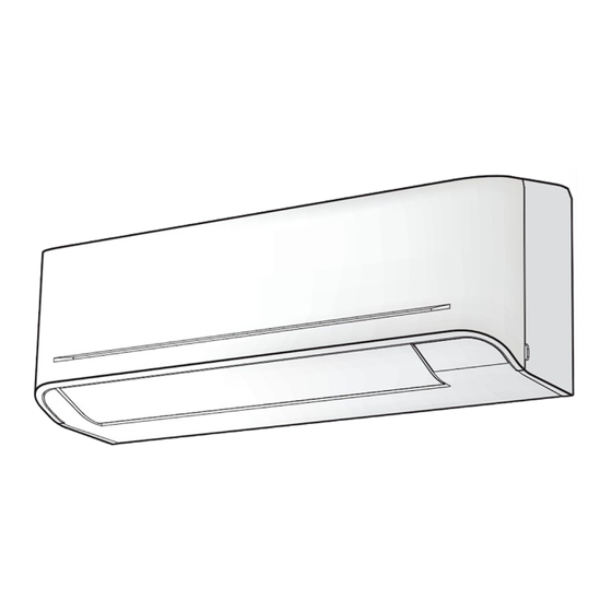
Table of Contents
Advertisement
R32
INSTALLATION MANUAL
ENGLISH
AIR CONDITIONER (SPLIT TYPE)
Scan QR CODE to access installation and owner's manual on website.
https://www.toshiba-carrier.co.th/manuals/default.aspx
Manual are available in AR/BG/CZ/DA/DE/EL/EN/ES/ET/FI/FR/
HR/HU/IT/LT/LV/NL/NO/PL/PT/RO/RU/SK/SL/SV.
Indoor unit
RAS-B05, 07, 10, 13, 16, 18B2KVG-E
Outdoor unit
RAS-05, 07, 10, 13, 16, 18B2AVG-E
1144180139A
Advertisement
Table of Contents

Summary of Contents for Toshiba RAS-B05B2KVG-E
- Page 1 INSTALLATION MANUAL ENGLISH AIR CONDITIONER (SPLIT TYPE) Scan QR CODE to access installation and owner’s manual on website. https://www.toshiba-carrier.co.th/manuals/default.aspx Manual are available in AR/BG/CZ/DA/DE/EL/EN/ES/ET/FI/FR/ HR/HU/IT/LT/LV/NL/NO/PL/PT/RO/RU/SK/SL/SV. Indoor unit RAS-B05, 07, 10, 13, 16, 18B2KVG-E Outdoor unit RAS-05, 07, 10, 13, 16, 18B2AVG-E...
-
Page 2: Accessory Parts
ACCESSORY PARTS ACCESSORY PARTS Indoor Unit Part name Part name Installation plate × 1 Wireless remote controller × 1 Battery × 2 Remote controller holder × 1 Mounting screw × 6 Flat head wood screw × 2 Owner’s Manual × 1 Installation Manual ×... -
Page 3: Optional Installation Parts
INSTALLATION DIAGRAM OF INDOOR AND OUTDOOR UNITS INSTALLATION DIAGRAM OF INDOOR AND OUTDOOR UNITS For the rear left, bottom left and left piping Wall Hook Installation plate Cut out a piece of SPACER from indoor unit packaging box, roll it and insert between the indoor unit and wall to tilt the indoor unit for better operation. -
Page 4: Indoor Unit
INDOOR UNIT INDOOR UNIT Mounting the installation plate Installation Place (Unit : mm) • A place which provides the spaces around the indoor unit as shown in the diagram. Hook • A place where there are no obstacles near the air inlet and outlet. •... -
Page 5: Piping And Drain Hose Installation
When the installation plate is directly mounted How to remove the drain hose • The drain hose can be removed by removing the on the wall screw securing the drain hose and then pulling out 1. Securely fi t the installation plate onto the wall by screwing it in the upper the drain hose. -
Page 6: Indoor Unit Fixing
NOTE Drainage If the pipe is bent incorrectly, the indoor unit may unstably be set on the wall. After passing the connecting pipe through the pipe hole, connect the 1. Run the drain hose sloped downwards. connecting pipes to the auxiliary pipes and wrap the facing tape around NOTE them. -
Page 7: Outdoor Unit
OUTDOOR UNIT OUTDOOR UNIT Installation Place CAUTION 1. Install the outdoor unit without anything blocking the air discharging. • A place which provides the spaces around the outdoor unit as shown in 2. When the outdoor unit is installed in a place always exposed to strong the diagram. - Page 8 (Unit : N·m) CAUTION Outer dia. of copper pipe Tightening torque • KEEP IMPORTANT 7 POINTS FOR PIPING WORK. Ø6.35 mm 14 to 18 (1.4 to 1.8 kgf·m) (1) Take away dust and moisture (inside of the connecting pipes). (2) Tighten the connections (between pipes and unit). Ø9.52 mm 30 to 42 (3.0 to 4.2 kgf·m) (3) Evacuate the air in the connecting pipes using a VACUUM PUMP.
-
Page 9: Electrical Works
ELECTRICAL WORKS ELECTRICAL WORKS Model RAS-B05B2KVG-E RAS-B07B2KVG-E RAS-B10B2KVG-E RAS-B13B2KVG-E RAS-B16B2KVG-E RAS-B18B2KVG-E Power source 50Hz, 220 – 240V / 60Hz, 220 – 230V Single phase 50Hz, 220 – 240V Single phase Maximum running current 6.2A 6.2A 8.0A 8.0A 9.30A 9.30A Circuit breaker rating Power supply cable H07RN-F or 60245 IEC66 (1.25 mm... -
Page 10: Power Supply And Connecting Cable Connection
Power Supply and Connecting Cable Connection Power Supply Input at Outdoor Unit Terminal Block Indoor Unit Outdoor Unit Stripping length of the Connecting cable Connecting cable 1 2 3 connect to 1 2 3 connecting cable Earth line Terminal block (1 2 3) 50 mm 10 mm Earth line... -
Page 11: Gas Leak Test
OTHERS OTHERS Gas Leak Test Test Operation To switch the TEST RUN (COOL) mode, press [RESET] button for 10 seconds. (The beeper will make a short beep.) Check places for the indoor unit. OPERATION / RESET Button Check places for the outdoor unit.


Need help?
Do you have a question about the RAS-B05B2KVG-E and is the answer not in the manual?
Questions and answers