Table of Contents
Advertisement
Quick Links
Download this manual
See also:
User Manual
Copyright Notice:
Copyright Notice:
Copyright Notice:
Copyright Notice:
Copyright Notice:
No part of this installation guide may be reproduced, transcribed, transmitted, or trans-
lated in any language, in any form or by any means, except duplication of documen-
tation by the purchaser for backup purpose, without written consent of ASRock Inc.
Products and corporate names appearing in this guide may or may not be registered
trademarks or copyrights of their respective companies, and are used only for identifica-
tion or explanation and to the owners' benefit, without intent to infringe.
Disclaimer:
Disclaimer:
Disclaimer:
Disclaimer:
Disclaimer:
Specifications and information contained in this guide are furnished for informational
use only and subject to change without notice, and should not be constructed as a
commitment by ASRock. ASRock assumes no responsibility for any errors or omissions
that may appear in this guide.
With respect to the contents of this guide, ASRock does not provide warranty of any kind,
either expressed or implied, including but not limited to the implied warranties or
conditions of merchantability or fitness for a particular purpose. In no event shall
ASRock, its directors, officers, employees, or agents be liable for any indirect, special,
incidental, or consequential damages (including damages for loss of profits, loss of
business, loss of data, interruption of business and the like), even if ASRock has been
advised of the possibility of such damages arising from any defect or error in the guide
or product.
This device complies with Part 15 of the FCC Rules. Operation is subject to the
following two conditions:
(1) this device may not cause harmful interference, and
(2) this device must accept any interference received, including interference that
may cause undesired operation.
CALIFORNIA, USA ONLY
The Lithium battery adopted on this motherboard contains Perchlorate, a toxic
substance controlled in Perchlorate Best Management Practices (BMP) regulations
passed by the California Legislature. When you discard the Lithium battery in
California, USA, please follow the related regulations in advance.
"Perchlorate Material-special handling may apply, see
www.dtsc.ca.gov/hazardouswaste/perchlorate"
ASRock Website: http://www.asrock.com
Copyright©2009 ASRock INC. All rights reserved.
Published February 2009
ASRock G965M-S Motherboard
1 1 1 1 1
Advertisement
Table of Contents

Related Manuals for ASROCK G965M-S


Summary of Contents for ASROCK G965M-S
- Page 1 ASRock. ASRock assumes no responsibility for any errors or omissions that may appear in this guide. With respect to the contents of this guide, ASRock does not provide warranty of any kind, either expressed or implied, including but not limited to the implied warranties or conditions of merchantability or fitness for a particular purpose.
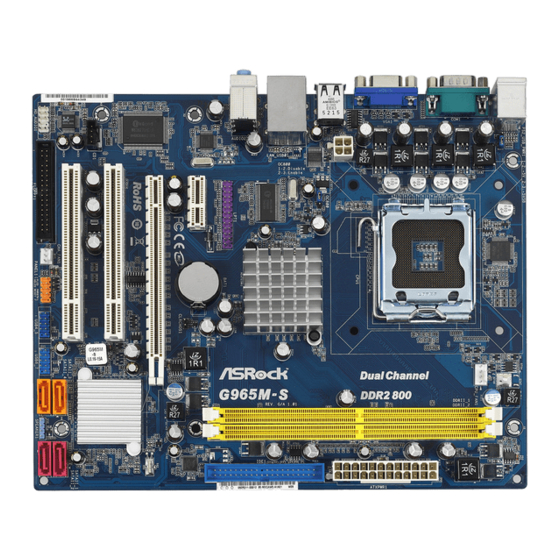
- Page 2 North Bridge Controller USB 2.0 Header (USB6_7, Blue) CPU Fan Connector (CPU_FAN1) BIOS SPI Chip 2 x 240-pin DDR2 DIMM Slots USB 2.0 Header (USB4_5, Blue) (Dual Channel: DDRII_1, DDRII_2; Yellow) System Panel Header (PANEL1, Orange) ATX Power Connector (ATXPWR1)
- Page 3 COM Port Microphone (Pink) PS/2 Keyboard Port (Purple) * To enable Multi-Streaming function, you need to connect a front panel audio cable to the front panel audio header. Please refer to below steps for the software setting of Multi- Streaming.
- Page 4 ASRock’s commitment to quality and endurance. This Quick Installation Guide contains introduction of the motherboard and step-by-step installation guide. More detailed information of the motherboard can be found in the user manual presented in the Support CD.
- Page 5 Specifications 1 . 2 1 . 2 Specifications Specifications Platform - Micro ATX Form Factor: 9.6-in x 7.7-in, 24.4 cm x 19.6 cm ® - LGA 775 for Intel Core 2 Extreme / Core 2 Quad / Core 2 Duo / Pentium ®...
- Page 6 Overclocking may affect your system stability, or even cause damage to the components and devices of your system. It should be done at your own risk and expense. We are not responsible for possible damage caused by overclocking.
- Page 7 Before installing SATAII hard disk to SATAII connector, please read the “SATAII Hard Disk Setup Guide” on page 23 of “User Manual” in the support CD to adjust your SATAII hard disk drive to SATAII mode. You can also connect SATA hard disk to SATAII connector directly.
- Page 8 13. While CPU overheat is detected, the system will automatically shutdown. Before you resume the system, please check if the CPU fan on the motherboard functions properly and unplug the power cord, then plug it back again. To improve heat dissipation, remember to spray thermal grease between the CPU and the heatsink when you install the PC system.
- Page 9 Before you insert the 775-LAND CPU into the socket, please check if the CPU surface is unclean or if there is any bent pin on the socket. Do not force to insert the CPU into the socket if above situation is found.
- Page 10 775-LAND CPU For proper inserting, please ensure to match the two orientation key notches of the CPU with the two alignment keys of the socket. Step 2-3. Carefully place the CPU into the socket by using a purely vertical motion.
- Page 11 1. It is recommended to use the cap tab to handle and avoid kicking off the PnP cap. 2. This cap must be placed if returning the motherboard for after service. Step 4. Close the socket: Step 4-1. Rotate the load plate onto the IHS.
- Page 12 Unlock a DIMM slot by pressing the retaining clips outward. Step 2. Align a DIMM on the slot such that the notch on the DIMM matches the break on the slot. The DIMM only fits in one correct orientation. It will cause permanent damage to the motherboard and the DIMM if you force the DIMM into the slot at incorrect orientation.
- Page 13 2.4 Expansion Slots (PCI and PCI Express Slots) 2.4 Expansion Slots (PCI and PCI Express Slots) There are 2 PCI slots and 2 PCI Express slots on this motherboard. PCI slots: PCI slots are used to install expansion cards that have the 32-bit PCI interface. PCIE slots: PCIE1 (PCIE x1 slot) is used for PCI Express cards with x1 lane width cards, such as Gigabit LAN card, SATA2 card, etc.
- Page 14 2-pin jumper (see p.2 No. 8) Note: CLRCMOS1 allows you to clear the data in CMOS. The data in CMOS includes system setup information such as system password, date, time, and system setup parameters. To clear and reset the system parameters to default setup, please turn off the computer and unplug the power cord from the power supply.
- Page 15 IDE devices 80-conductor ATA 66/100/133 cable Note: Please refer to the instruction of your IDE device vendor for the details. Serial ATAII Connectors These Serial ATAII (SATAII) connectors support SATAII (SATAII_1: see p.2, No. 11)
- Page 16 HDA to function correctly. Please follow the instruction in our manual and chassis manual to install your system. 2. If you use AC’97 audio panel, please install it to the front panel audio header as below: A.
- Page 17 Though this motherboard provides 4-Pin CPU fan (Quiet Fan) support, the 3-Pin CPU fan still can work successfully even without the fan speed control function. If you plan to connect the 3-Pin CPU fan to the CPU fan connector on this motherboard, please connect it to Pin 1-3.
- Page 18 (see p.2, No. 6) Though this motherboard provides 24-pin ATX power connector, it can still work if you adopt a traditional 20-pin ATX power supply. To use the 20-pin ATX power supply, please plug your power supply along with Pin 1 and Pin 13.
-
Page 19: Driver Installation Guide
STEP 2: Connect the SATA power cable to the SATA / SATAII hard disk. STEP 3: Connect one end of the SATA data cable to the motherboard’s SATAII connector. STEP 4: Connect the other end of the SATA data cable to the SATA / SATAII hard disk. 2 . 8 2 . - Page 20 To begin using the Support CD, insert the CD into your CD-ROM drive. It will display the Main Menu automatically if “AUTORUN” is enabled in your computer. If the Main Menu does not appear automatically, locate and double-click on the file “ASSETUP.
- Page 21 ASRock. Esta Guía rápida de instalación contiene una introducción a la placa base y una guía de instalación paso a paso. Puede encontrar una información más detallada sobre la placa base en el manual de usuario incluido en el CD de soporte.
- Page 22 Especificación Especificación Especificación 1 . 2 1 . 2 Especificación Plataforma - Factor forma Micro ATX: 24,4 cm x 19,6 cm, 9,6” x 7,7” Procesador - LGA 775 para Intel ® Core 2 Extreme / Core 2 Quad / Core ®...
- Page 23 - 24-pin cabezal de alimentación ATX - 4-pin conector de ATX 12V power - Conector de Audio Interno - Conector de audio de panel frontal - 2 x Conector USB 2.0 (compatible con 4 puertos USB 2.0) (vea ATENCIÓN 9) BIOS - 4Mb AMI BIOS - AMI legal BIOS - Soporta “Plug and Play”...
- Page 24 ADVERTENCIA Tenga en cuenta que hay un cierto riesgo implícito en las operaciones de aumento de la velocidad del reloj, incluido el ajuste del BIOS, aplicando la tecnología de aumento de velocidad liberada o utilizando las herramientas de aumento de velocidad de otros fabricantes.
- Page 25 10. Es una herramienta de overclocking de ASRock de usuario-fácil que le permite a supervisar su sistema por la función de monitor de hardware y overclock sus dispositivos de hardware para obtener el mejor funcionamiento del sistema bajo el entorno de Windows ®...
- Page 26 3 para habilitar +5VSB (vea p.2, N. 1) (standby) para PS/2 o USB wake up events. Atención: Para elegir +5VSB, se necesita corriente mas que 2 Amp proveida por la fuente de electricidad. Limpiar CMOS (CLRCMOS1, jumper de 2 pins) jumper de 2 pins (vea p.2, N.
- Page 27 1.4 Cabezales y Conectores en Placas 1.4 Cabezales y Conectores en Placas Los conectores y cabezales en placa NO son puentes. NO coloque las cubiertas de los puentes sobre estos cabezales y conectores. El colocar cubiertas de puentes sobre los conectores y cabezales provocará...
- Page 28 2. Si utiliza el panel de sonido AC’97, instálelo en la cabecera de sonido del panel frontal de la siguiente manera: A. Conecte Mic_IN (MIC) a MIC2_L.
- Page 29 Vista / Vista de 64 bits: Vaya a la ficha «Micrófono central» en el panel Control de Realtek. Haga clic en «Establecer dispositivo predeterminado» para convertir el micrófono central en el dispositivo de grabación predeterminado. Cabezal de panel de sistema...
- Page 30 Aunque esta placa base proporciona compatibilidad para un ventilador (silencioso) de procesador de 4 contactos, el ventilador de procesador de 3 contactos seguirá funcionando correctamente incluso sin la función de control de velocidad del ventilador. Si pretende enchufar el ventilador de procesador de 3 contactos en el conector del ventilador de procesador de esta placa base, conéctelo al contacto 1-3.
- Page 31 Para iniciar la instalación, ponga el CD en el lector de CD y se desplegará el Menú Principal automáticamente si «AUTORUN» está habilitado en su computadora. Si el Menú...
- Page 32 Gratos por comprar nossa placa–mãe G965M-S, um produto confiável feito com ASRock um estrito controle de qualidade consistente. Com um excelente desempenho, essa placa é dotada de um projeto robusto que atende a ASRock de compromisso com a qualidade e durabilidade.
- Page 33 1.2 Especificações 1.2 Especificações 1.2 Especificações 1.2 Especificações 1.2 Especificações Plataforma - Formato Micro ATX: 9,6 pol. x 7,7 pol., 24,4 cm x 19,6 cm - Socket Intel ® Dual Core Core 2 Extreme / Core 2 Quad / Core 2 Duo / Pentium ®...
- Page 34 - Medição de temperatura da placa-mãe - Tacômetros de ventilador do Processador - Tacômetros de ventilador do chassis - Ventoinha silenciosa para a CPU - Monitoramento de voltagem : +12 V, +5 V, +3.3 V, Vcore ® ® Sistema - Microsoft...
- Page 35 AVISO Tenha em atenção que a operação de overclocking envolve alguns riscos, nomeadamente no que diz respeito ao ajuste das definições do BIOS, à aplicação da tecnologia Untied Overclocking ou à utilização de ferramentas de overclocking de terceiros. O overclocking pode afectar a estabilidade do seu sistema ou até mesmo causar danos ao nível dos componentes e dispositivos que integram o sistema.
- Page 36 10. É uma ferramenta de overclocking da ASRock fácil de utilizar que lhe permite vigiar i seu sistema via a função de monitorização de hardware e proceder ao overclock dos dispositivos de hardware para obter o melhor desempenho em ambiente Windows ®...
- Page 37 (veja a folha 2, No. 1) para PS/2 ou eventos de wake up na USB. Nota: Para escolher +5VSB, é preciso uma corrente de stand by de 2 A ou mais. Restaurar CMOS (CLRCMOS1, jumper de 2 pinos) jumper de 2 pinos (veja a folha 2, No.
- Page 38 1.4 Conectores 1.4 Conectores 1.4 Conectores 1.4 Conectores Os conectores NÃO SÃO jumpers. NÃO coloque capas de jumper sobre estes conectores. A colocação de pontos de jumper sobre os conectores causará danos irreversíveis à placa-mãe. Conector Figura Descrição Conector primário (Azul) (IDE1 de 39 pinos, veja a folha 2, No.
- Page 39 Siga s instruções que aparecem no manual e no manual do chassis para instalar o sistema. 2. Se utilizar o painel de áudio AC’97, instale-o no cabeçalho de áudio do painel frontal, como a figura abaixo mostra: A. Ligue o Mic_IN (MIC) ao MIC2_L.
- Page 40 2000 / XP / XP 64-bit OS: Queira seleccionar “Front Mic” (Microfone Frontal) como dispositivo de gravação predefinido. Se quer ouvir a sua voz através do microfone frontal, queira desmarcar o ícone “Mute” (Sem som) em “Front Mic” (Microfone Frontal) da parte “Playback” (Reprodução).
- Page 41 Apesar de esta placa-mãe possuir 4 apoios para uma ventoinha de CPU (Ventoinha silenciosa), uma ventoinha de 3 pinos para CPU poderá funcionar mesmo sem a função de controlo de velocidade da ventoinha. Se pretender ligar uma ventoinha de 3 pinos para CPU ao conector de ventoinha do CPU nesta placa-mãe, por favor, ligue-a aos pinos 1-3.
- Page 42 Mãe contem: drivers e utilitários necessários para um melhor desempenho da placa Mãe. Para começar a usar o CD de instalação, introduza o CD na leitora de CD-ROM do computador. Automaticamente iniciará o menu principal, casa o AUTORUN esteja ativado.
Need help?
Do you have a question about the G965M-S and is the answer not in the manual?
Questions and answers