ASROCK G31M-VS2 User Manual
Micro atx form factor
Hide thumbs
Also See for G31M-VS2:
- User manual (43 pages) ,
- Brochure (5 pages) ,
- Installation manual (107 pages)

Related Manuals for ASROCK G31M-VS2


Summary of Contents for ASROCK G31M-VS2
-
Page 1: User Manual
G31M-VS2 User Manual Version 1.2 Published March 2010 Copyright©2010 ASRock INC. All rights reserved. 1 1 1 1 1... - Page 2 (including damages for loss of profits, loss of business, loss of data, interruption of business and the like), even if ASRock has been advised of the possibility of such damages arising from any defect or error in the manual or product.
-
Page 3: Table Of Contents
Contents Contents Contents Contents Contents 1 Introduction 1 Introduction 1 Introduction 1 Introduction 1 Introduction ....................................................5 5 5 5 5 1.1 Package Contents ............5 1.2 Specifications ..............6 1.3 Motherboard Layout ............10 1.4 I/O Panel ................. 11 2 Installation 2 Installation ............. -
Page 4: Software Support
4 Software Support 4 Software Support 4 Software Support .......... 4 Software Support 4 Software Support ..................................43 4.1 Install Operating System ..........43 4.2 Support CD Information ........... 43 4.2.1 Running Support CD ..........43 4.2.2 Drivers Menu ............43 4.2.3 Utilities Menu ............ -
Page 5: Introduction
In case any modifications of this manual occur, the updated version will be available on ASRock website without further notice. You may find the latest VGA cards and CPU support lists on ASRock website as well. ASRock website http://www.asrock.com If you require technical support related to this motherboard, please visit our website for specific information about the model you are using. -
Page 6: Specifications
1 . 2 1 . 2 1 . 2 1 . 2 1 . 2 Specifications Specifications Specifications Specifications Specifications - Micro ATX Form Factor: 8.9-in x 6.7-in, 22.6 cm x 17.0 cm Platform - LGA 775 for Intel Core 2 Extreme / Core 2 Quad / Core ®... - Page 7 64-bit / ® ® XP / XP 64-bit compliant - FCC, CE Certifications - EuP Ready (EuP ready power supply is required) (see CAUTION 14) * For detailed product information, please visit our website: http://www.asrock.com 7 7 7 7 7...
- Page 8 64-bit / Vista / XP 64-bit / XP SP1 or SP2. It is a user-friendly ASRock overclocking tool which allows you to surveil your system by hardware monitor function and overclock your hardware devices to get the best system performance under Windows ®...
- Page 9 10. ASRock Instant Flash is a BIOS flash utility embedded in Flash ROM. This convenient BIOS update tool allows you to update system BIOS without entering operating systems first like MS-DOS or Windows . With ® this utility, you can press <F6> key during the POST or press <F2> key to BIOS setup menu to access ASRock Instant Flash.
-
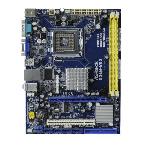
Page 10: Motherboard Layout
1.3 Motherboard Layout 1.3 Motherboard Layout 1.3 Motherboard Layout 1.3 Motherboard Layout 1.3 Motherboard Layout 17.0cm (6.7 in) PS2_USB_PWR1 CPU_FAN1 USB 2.0 T: USB2 B: USB3 USB 2.0 Super Intel Top: T: USB0 RJ-45 B: USB1 Chipset HD_AUDIO1 LPT1 PCIE1 AUDIO CODEC CMOS... -
Page 11: I/O Panel
1.4 I/O P 1.4 I/O P 1.4 I/O P 1.4 I/O P 1.4 I/O Panel anel anel anel anel PS/2 Mouse Port (Green) Microphone (Pink) USB 2.0 Ports (USB23) USB 2.0 Ports (USB01) RJ-45 Port VGA Port Line In (Light Blue) COM Port Line Out (Lime) PS/2 Keyboard Port (Purple) -
Page 12: Installation
Chapter 2 Installation Chapter 2 Installation G31M-VS2 is a Micro ATX form factor (8.9" x 6.7", 22.6 x 17.0 cm) motherboard. Before you install the motherboard, study the configuration of your chassis to en- sure that the motherboard fits into it. -
Page 13: Cpu Installation
2.3 CPU Installation 2.3 CPU Installation 2.3 CPU Installation 2.3 CPU Installation 2.3 CPU Installation For the installation of Intel 775-LAND CPU, please follow the steps below. 775-Pin Socket Overview Before you insert the 775-LAND CPU into the socket, please check if the CPU surface is unclean or if there is any bent pin on the socket. - Page 14 For proper inserting, please ensure to match the two orientation key notches of the CPU with the two alignment keys of the socket. Step 2-3. Carefully place the CPU into the socket by using a purely vertical motion. Step 2-4. Verify that the CPU is within the socket and properly mated to the orient keys.
-
Page 15: Installation Of Heatsink And Cpu Fan
Installation of CPU Fan and Heatsink Installation of CPU Fan and Heatsink Installation of CPU Fan and Heatsink Installation of CPU Fan and Heatsink Installation of CPU Fan and Heatsink This motherboard is equipped with 775-Pin socket that supports Intel 775-LAND CPU. Please adopt the type of heatsink and cooling fan compliant with Intel 775-LAND CPU to dissipate heat. -
Page 16: Installation Of Memory Modules (Dimm)
Modules (DIMM) y Modules (DIMM) y Modules (DIMM) G31M-VS2 motherboard provides two 240-pin DDR2 (Double Data Rate 2) DIMM slots, and supports Dual Channel Memory Technology. For dual channel configuration, you always need to install two identical (the same brand, speed, size and chip-type) memory modules in the DDR2 DIMM slots to activate Dual Channel Memory Technology. -
Page 17: Expansion Slots (Pci And Pci Express Slots)
2.6 Expansion Slots (PCI and PCI Express Slots) 2.6 Expansion Slots (PCI and PCI Express Slots) 2.6 Expansion Slots (PCI and PCI Express Slots) 2.6 Expansion Slots (PCI and PCI Express Slots) 2.6 Expansion Slots (PCI and PCI Express Slots) There are 1 PCI slot and 1 PCI Express slot on this motherboard. -
Page 18: Jumpers Setup
2.7 Jumpers Setup 2.7 Jumpers Setup 2.7 Jumpers Setup 2.7 Jumpers Setup 2.7 Jumpers Setup The illustration shows how jumpers are setup. When the jumper cap is placed on pins, the jumper is “Short”. If no jumper cap is placed on pins, the jumper is “Open”. The illustration shows a 3-pin jumper whose pin1 and pin2 are “Short”... -
Page 19: Onboard Headers And Connectors
2.8 Onboard Headers and Connectors 2.8 Onboard Headers and Connectors 2.8 Onboard Headers and Connectors 2.8 Onboard Headers and Connectors 2.8 Onboard Headers and Connectors Onboard headers and connectors are NOT jumpers. Do NOT place jumper caps over these headers and connectors. Placing jumper caps over the headers and connectors will cause permanent damage of the motherboard! Primary IDE connector (Blue) -
Page 20: Front Panel Audio Header
USB 2.0 Headers Besides four default USB 2.0 USB_PWR ports on the I/O panel, there are (9-pin USB6_7) DUMMY two USB 2.0 headers on this (see p.10 No. 17) motherboard. Each USB 2.0 header can support two USB USB_PWR 2.0 ports. USB_PWR (9-pin USB4_5) (see p.10 No. - Page 21 E. Enter BIOS Setup Utility. Enter Advanced Settings, and then select Chipset Configuration. Set the Front Panel Control option from [Auto] to [Enabled]. System Panel Header This header accommodates PLED+ PLED- PWRBTN# several system front panel (9-pin PANEL1) functions. (see p.10 No. 9) DUMMY RESET# HDLED-...
- Page 22 ATX 12V Connector Please note that it is necessary to connect a power supply with (4-pin ATX12V2) ATX 12V plug to this connector (see p.10 No. 2) so that it can provides sufficient power. Failing to do so will cause the failure to power up.
-
Page 23: Sataii Hard Disk Setup Guide
2 . 9 2 . 9 2 . 9 SAT T T T T AII Hard Disk Setup Guide AII Hard Disk Setup Guide AII Hard Disk Setup Guide AII Hard Disk Setup Guide 2 . 9 2 . 9 AII Hard Disk Setup Guide Before installing SATAII hard disk to your computer, please carefully read below SATAII hard disk setup guide. -
Page 24: Installation
2 . 1 0 2 . 1 0 Serial A 2 . 1 0 Serial A Serial A Serial AT T T T T A (SA A (SA A (SA A (SAT T T T T A) / Serial A A) / Serial A A) / Serial AT T T T T AII (SA A) / Serial A... -
Page 25: Introduction
Chapter 3: BIOS SETUP UTILITY Chapter 3: BIOS SETUP UTILITY Chapter 3: BIOS SETUP UTILITY Chapter 3: BIOS SETUP UTILITY Chapter 3: BIOS SETUP UTILITY 3.1 Introduction 3.1 Introduction 3.1 Introduction 3.1 Introduction 3.1 Introduction This section explains how to use the BIOS SETUP UTILITY to configure your system. The SPI Memory on the motherboard stores the BIOS SETUP UTILITY. -
Page 26: Navigation Keys
System Time [ :00:09] select a field. System Date [Fri 01/08/2010] Use [+] or [-] to configure system Time. BIOS Version : G31M-VS2 P1.00 Processor Type : Intel (R) CPU 2.80GHz (64bit) Processor Speed : 2800MHz Microcode Update : F62/F... -
Page 27: Smart Screen
Load power saving setup default. F6 key can be used for this operation. ASRock Instant Flash ASRock Instant Flash is a BIOS flash utility embedded in Flash ROM. This convenient BIOS update tool allows you to update system BIOS without entering operating systems first like MS-DOS or Windows . -
Page 28: Advanced Screen
3.4 Advanced Screen Advanced Screen Advanced Screen Advanced Screen Advanced Screen In this section, you may set the configurations for the following items: CPU Configuration, Chipset Configuration, ACPI Configuration, Storage Configuration, PCIPnP Configuration, SuperIO Configuration, and USB Configuration. BIOS SETUP UTILITY Main Smart Advanced... - Page 29 Boot Failure Guard Enable or disable the feature of Boot Failure Guard. Spread Spectrum This item should always be [Auto] for better system stability. Ratio Status This is a read-only item, which displays whether the ratio status of this motherboard is “Locked” or “Unlocked”. If it shows “Unlocked”, you will find an item Ratio CMOS Setting appears to allow you changing the ratio value of this motherboard.
-
Page 30: Chipset Configuration
Intel (R) SpeedStep(tm) tech. Intel (R) SpeedStep(tm) tech. is Intel’s new power saving technology. Processor can switch between multiple frequency and voltage points to enable power savings. The default value is [Auto]. Configuration options: [Auto], [Enabled] and [Disabled]. If you install Windows XP and select ®... - Page 31 DRAM tCL Use this item to adjust the means of memory accessing. Configuration options are [6], [5], [4], [3] and [Auto]. DRAM tRCD This controls the latency between the DRAM active command and the read / write command. Configuration options: [3 DRAM Clocks], [4 DRAM Clocks], [5 DRAM Clocks], [6 DRAM Clocks] and [Auto].
- Page 32 Front Panel Select [Auto], [Enabled] or [Disabled] for the onboard HD Audio Front Panel. OnBoard Lan This allows you to enable or disable the “OnBoard Lan” feature. DRAM Voltage Use this to select DRAM Voltage. Configuration options: [Auto], [1.794V], [1.851V], [1.908V], [1.965V], [2.029V], [2.086V], [2.144V] and [2.201V]. The default value of this feature is [Auto].
-
Page 33: Acpi Configuration
3.4.3 3.4.3 3.4.3 ACPI Configuration 3.4.3 3.4.3 ACPI Configuration ACPI Configuration ACPI Configuration ACPI Configuration BIOS SETUP UTILITY Advanced ACPI Configuration Select auto-detect or disable the STR feature. Suspend To RAM [Disabled] [Power Off] Restore on AC/Power Loss [Disabled] Ring-In Power On [Disabled] PCI Devices Power On [Disabled]... -
Page 34: Storage Configuration
3.4.4 3.4.4 3.4.4 Storage Configuration Storage Configuration Storage Configuration Storage Configuration 3.4.4 3.4.4 Storage Configuration BIOS SETUP UTILITY Advanced Set [Compatible] IDE Configuration when Legacy OS (MS-DOS, Win NT) ATA/IDE Configuration [Enhanced] device is used. Set [Enhanced] SATAII_1 [Hard Disk] when Native OS SATAII_2 [Not Detected]... - Page 35 BIOS SETUP UTILITY Advanced Primary IDE Master Select the type of device connected :Hard Disk Device to the system. Vendor :ST340014A :40.0 GB Size LBA Mode :Supported Block Mode :16Sectors PIO Mode Async DMA :MultiWord DMA-2 Ultra DMA :Ultra DMA-5 S.M.A.R.T.
-
Page 36: Pcipnp Configuration
S.M.A.R.T. Use this item to enable or disable the S.M.A.R.T. (Self-Monitoring, Analysis, and Reporting Technology) feature. Configuration options: [Disabled], [Auto], [Enabled]. 32-Bit Data Transfer Use this item to enable 32-bit access to maximize the IDE hard disk data transfer rate. 3.4.5 3.4.5 3.4.5 PCIPnP Configuration... -
Page 37: Super Io Configuration
3.4.6 3.4.6 Super IO Configuration Super IO Configuration 3.4.6 3.4.6 Super IO Configuration 3.4.6 Super IO Configuration Super IO Configuration BIOS SETUP UTILITY Advanced Configure Super IO Chipset Allow BIOS to Enable or Disable Floppy Controller. Serial Port Address [3F8 / IRQ4] Parallel Port Address [378] Parallel Port Mode... -
Page 38: Usb Configuration
3.4.7 3.4.7 USB Configuration 3.4.7 USB Configuration USB Configuration USB Configuration 3.4.7 3.4.7 USB Configuration BIOS SETUP UTILITY Advanced USB Configuration To enable or disable the onboard USB controllers. [Enabled] USB Controller [Enabled] USB 2.0 Support Legacy USB Support [Enabled] Select Screen Select Item Change Option... -
Page 39: Hardware Health Event Monitoring Screen
3.5 Hardware Health Event Monitoring Screen Hardware Health Event Monitoring Screen Hardware Health Event Monitoring Screen Hardware Health Event Monitoring Screen Hardware Health Event Monitoring Screen In this section, it allows you to monitor the status of the hardware on your system, including the parameters of the CPU temperature, motherboard temperature, CPU fan speed, chassis fan speed, and the critical voltage. -
Page 40: Boot Screen
3.6 Boot Screen Boot Screen Boot Screen Boot Screen Boot Screen In this section, it will display the available devices on your system for you to config- ure the boot settings and the boot priority. BIOS SETUP UTILITY Main Smart Advanced H/W Monitor Boot... -
Page 41: Security Screen
Boot From Onboard LAN Use this item to enable or disable the Boot From Onboard LAN feature. Boot Up Num-Lock If this item is set to [On], it will automatically activate the Numeric Lock function after boot-up. Security Screen Security Screen 3.7 Security Screen Security Screen Security Screen... -
Page 42: Exit Screen
3.8 Exit Screen Exit Screen Exit Screen Exit Screen Exit Screen BIOS SETUP UTILITY Main Smart Advanced H/W Monitor Boot Security Exit Exit Options Exit system setup after saving the Save Changes and Exit changes. Discard Changes and Exit Discard Changes F10 key can be used for this operation. -
Page 43: Install Operating System
C o n t a c t I n f o r m a t i o n If you need to contact ASRock or want to know more about ASRock, welcome to visit ASRock’s website at http://www.asrock.com; or you may contact your...
Need help?
Do you have a question about the G31M-VS2 and is the answer not in the manual?
Questions and answers