
Related Manuals for ASROCK G PRO


Summary of Contents for ASROCK G PRO
-
Page 1: User Manual
G Pro / GV Pro User Manual Published October 2002 Copyright©2002 ASRock INC. All rights reserved. 1 1 1 1 1... - Page 2 In no event shall ASRock, its directors, officers, employees, or agents be liable for any indirect, special, incidental, or consequential damages (including damages for loss of profits, loss of business, loss of data, interruption of business and the like), even if ASRock has been advised of the possibility of such damages arising from any defect or error in the manual or product.
-
Page 3: Table Of Contents
3.1 BIOS Setup Program ............15 3.1.1 BIOS Menu Bar ............15 3.1.2 Legend Bar ............. 15 3.2 Main Menu ..............16 3.3 Advanced, Security, Power, Boot, and Exit Menus ..18 4 Software Support 4 Software Support .................. -
Page 4: Introduction
Chapter 1 Introduction Chapter 1 Introduction Chapter 1 Introduction Thank you for purchasing ASRock G Pro / GV Pro motherboard, a reliable motherboard produced under ASRock’s consistently stringent quality control. It delivers excellent performance with robust design conforming to ASRock’s commitment to quality and endurance. - Page 5 While CPU overheat is detected, the system will automatically shutdown. Please check if the CPU fan on the motherboard functions properly before you resume the system. Although G Pro/GV Pro offers stepless control, it is not recommended to perform over clocking.
-
Page 6: Motherboard Layout (G Pro)
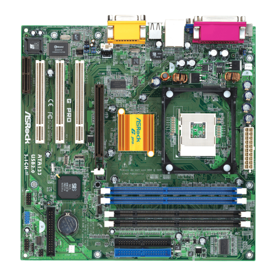
1.3 Motherboard Layout (G Pro 1.3 Motherboard Layout (G Pro 1.3 Motherboard Layout (G Pro 1.3 Motherboard Layout (G Pro) 1.3 Motherboard Layout (G Pro 24.4cm (9.6 in) CPU_FAN1 CPU_FAN1 PS/2 ATX PWR1 Mouse PS2_USB_PWR1 PS/2 Keyboard USB01 USB23 Line out... -
Page 7: Motherboard Layout (Gv Pro)
1.4 Motherboard Layout (GV Pro 1.4 Motherboard Layout (GV Pro 1.4 Motherboard Layout (GV Pro 1.4 Motherboard Layout (GV Pro 1.4 Motherboard Layout (GV Pro) 24.4cm (9.6 in) CPU_FAN1 CPU_FAN1 PS/2 ATX PWR1 Mouse PS2_USB_PWR1 PS/2 Keyboard USB01 USB23 Line out... -
Page 8: Asrock I/O
1.5 ASRock I/O 1.5 ASRock I/O (G Pro / GV Pro) (G Pro / GV Pro) 1.5 ASRock I/O 1.5 ASRock I/O 1.5 ASRock I/O (G Pro / GV Pro) (G Pro / GV Pro) (G Pro / GV Pro) -
Page 9: Installation
Chapter 2 Installation Chapter 2 Installation G Pro / GV Pro is a Micro ATX form factor (9.6" x 9.6", 24.4 x 24.4 cm) motherboard. Before you install the motherboard, study the configuration of your chassis to en- sure that the motherboard fits into it. -
Page 10: Installation Of Heatsink And Cpu Fan
CPU into the socket to avoid bending of the pins. Step 4. When the CPU is in place, press it firmly on the socket while you push down the socket lever to secure the CPU. The lever clicks on the side tab to indicate that it is locked. -
Page 11: Expansion Slots
2.6 Expansion Slots (PCI, AMR, and AGP Slots) 2.6 Expansion Slots (PCI, AMR, and AGP Slots) There are 3 PCI slots and 1 AMR slot on both G Pro and GV Pro motherboards. Additionally, there is one AGP slot on G Pro. -
Page 12: Jumpers Setup
(see p.6/p.7 item 22) +5VSB (standby) for PS/2 or USB wake up events. +5VSB Note: To select +5VSB, it requires 2 Amp and higher standby current. CLRCMOS Disconnect the power cord, (see p.6/p.7 item 17) then short the solder points... - Page 13 Note: To optimize compatibility and performance, please connect your hard disk drive to the primary IDE connector (IDE1, blue) and CD-ROM to the secondary IDE connector (IDE2, black). USB header ASRock I/O already (9-pin USB45) provided 4 default USB ports.
- Page 14 CPU fan connector Connect the fan cable to the (3-pin CPU_FAN1) connector matching the black (see p.6/p.7 item 3) wire to the ground pin. ATX power connector Connect an ATX power (20-pin ATXPWR1) supply to the connector. (see p.6/p.7 item 1)
-
Page 15: Bios Setup
Flash Memory on the motherboard stores the BIOS Setup Utility. When you start up the computer, there is a chance for you to run the BIOS Setup. Press <F2> during the Power-On-Self-Test (POST) to enter the BIOS Setup Utility, otherwise, POST continues with its test routines. -
Page 16: Main Menu
Enter:Select Sub-Menu System Date [Month/Day/Year] Set the system date that you specify. Valid values for month, day, and year are Month: (Jan to Dec), Day: (1 to 31), Year: (up to 2099). Use keys to move between the Month, Day and Year fields. - Page 17 If the auto- detection fails, it may due to that the hard disk is too old or too new. If the hard disk was already formatted on an older system, the BIOS Setup may detect incorrect parameters.
-
Page 18: Advanced, Security, Power, Boot, And Exit Menus
LBA Mode This allows user to select the LBA mode for a hard disk > 512 MB under DOS and Windows; for Netware and UNIX user, select [Off] to disable the LBA mode. -
Page 19: Installing Operating System
4.2.1 Running The Support CD 4.2.1 Running The Support CD To begin using the support CD, insert the CD into your CD-ROM drive. The CD automatically displays the Main Menu if “AUTORUN” is enabled in your computer. If the Main Menu did not appear automatically, locate and double click on the file ASSETUP.EXE from the BIN folder in the Support CD to display the menus. -
Page 20: Advanced Menu
OnBoard VGA Share Memory: This allows you to select the size of share memory for onboard VGA. Onboard VGA will get better resolution if larger size of share memory is selected. Please do not select [None] if AGP or PCI graphics card is not inserted. -
Page 21: Resource Configuration
OnBoard Serial Port: Use this to set addresses for the onboard serial ports or disable serial ports. Configuration options: [Auto], [Disabled], [3F8 / IRQ4 / COM1], [2F8 / IRQ3 / COM2], [3E8 / IRQ4 / COM3], [2E8 / IRQ3 / COM4]. OnBoard Infrared Port: This allows you to enable or disable the onboard infrared port feature. -
Page 22: Security Menu
Set User Password: Press <Enter> to set User Password. Valid password can be a 1 to 6 alphanumeric characters combination. If you already have a password, you must enter your current password first in order to create a new password. -
Page 23: Power Menu
Ring-In Power On: Use this to enable or disable Ring-in signals to turn on the system from the power-soft-off mode. PME# Power On: Use this to enable or disable PCI PME# to turn on the system from the power-soft-off mode. -
Page 24: Boot Menu
4. Boot Setup Menu 4. Boot Setup Menu 4. Boot Setup Menu Quick Boot Mode: This mode speeds up the boot-up routine by skipping memory retestings. Boot-time Diagnostic Screen: This screen shows CPU and hardware information during Power-On-Self-Test (POST) routine. If this screen is disabled, only ASRock logo is shown during the boot up process. - Page 25 Exit Saving Changes: After you enter the sub-menu, the message “Save current settings and exit” will appear. If you press <ENTER>, it will save the current settings and exit the BIOS SETUP Utility. Exit Discarding Changes: After you enter the submenu, the message “Quit without saving changes”...
Need help?
Do you have a question about the G PRO and is the answer not in the manual?
Questions and answers