Table of Contents
Advertisement
Quick Links
Download this manual
See also:
Manual
Advertisement
Table of Contents

Related Manuals for ASROCK CORE 100HT


Summary of Contents for ASROCK CORE 100HT
- Page 1 Core 100 Series User Manual Version 1.0 Published April 2010 Copyright©2010 ASRock INC. All rights reserved. 1 1 1 1 1...
- Page 2 (including damages for loss of profits, loss of business, loss of data, interruption of business and the like), even if ASRock has been advised of the possibility of such damages arising from any defect or error in the manual or product.
- Page 3 • Read and follow all instructions in the documentation before you operate your system. • Do not use this product near water or a heated source such as a radiator. • Set up the system on a stable surface. •...
- Page 4 Optical Drive Safety Information Optical drives sold with this system contains a CLASS 1 LASER PRODUCT. CAUTION: Invisible laser radiation when open. Do not stare into beam or view directly with optical instruments. WARNING: Making adjustments or performing procedures other than those specified in the user’s manual may result in hazardous laser exposure.
-
Page 5: Table Of Contents
PowerDVD, PowerDirector, etc) ....30 6.4 Symantec Norton AntiVirus Software free bundle (Trial version) ..............32 6.5 THX TruStudio PRO Software free bundle ....33 6.6 ASRock AIWI Utility ............34 6.7 The best Apple charge companion - ASRock APP Charger ................ - Page 6 7.5 Hardware Health Event Monitoring Screen ....48 7.6 Boot Screen ..............48 7.6.1 Boot Settings Configuration ........49 7.7 Security Screen ............50 7.8 Exit Screen ..............51 8 Software Support 8 Software Support 8 Software Support 8 Software Support 8 Software Support ...........
-
Page 7: Introduction
ASRock’s commitment to quality and endurance. In this manual, chapter 1 and 2 contain introduction of the hardware and step-by- step guide to the hardware installation. Chapter 3 and 4 contain the configuration guide to BIOS setup and information of the Support CD. -
Page 8: Specifications
BIOS, or using the third-party overclocking tools. Overclocking may affect your system stability, or even cause damage to the components and devices of your system. It should be done at your own risk and expense. We are not responsible for possible damage caused by overclocking. -
Page 9: 1.3 System Motherboard Components
9. Mini-PCI Express expansion slot: For WiFi module 10. Clear CMOS jumper 11. SATA connector: For ODD SATA data cable 12. ATX5V output power connector for slim ODD & 2.5” HDD 13. SATA connector: For HDD SATA data cable 9 9 9 9 9... - Page 10 NOTE. 1. SATA and Power Connections Connect to ODD SATA & Power Connections Connect to SATA Connector (11) Connect to HDD Connect to ATX5V Power Connector (12) Connect to SATA Connector (13) 2. Fan Connection Fan connector Fan connector Ground...
-
Page 11: Rear Panel Connections
20. HDMI connector 21. USB2.0 ports: USB devices 22. LAN (RJ-45) port: Local Area Network 23. Line In (Blue) for 2/4/6 channel; Rear (Blue) for 8 channel 24. Center/LFE (Orange): Center / subwoofer speakers 25. Side port for side speakers... -
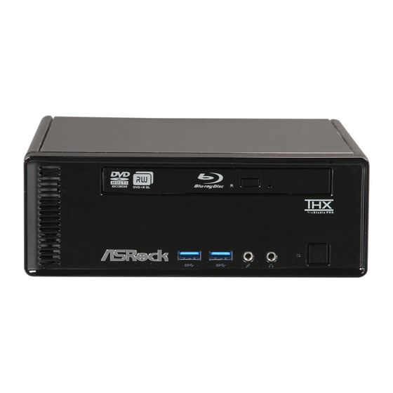
Page 12: 1.5 System Chassis
1.5 System Chassis 1.5 System Chassis 1.5 System Chassis Opening the system chassis 1. Remove the screws on the backside. 2. Slide the top panel backwards. 26. Optical Disc Drive 27. Power ON/OFF button with status indicator 28. Drive activity indicator 29. -
Page 13: Remote Controller
Some remote controller functions listed above are only available with the relative hardware equipments. If the hardware equipments you adopt are not compatible with the system, you are not allowed to use these functions. This product is designed to meet MCE standards. -
Page 14: System Quick Installation
Chapter 2 System Quick Installation Chapter 2 System Quick Installation Chapter 2 System Quick Installation 1. Connecting USB Devices (USB2.0 Ports) 2. Connecting VGA Monitor (Display (VGA) Port) 3. Connecting the Network (LAN (RJ-45) Port) 4. Connecting HDMI Device (HDMI Port) - Page 15 5. Connecting eSATA Device (eSATA Port) 6. Connecting External Audio Device (Line In Port for 2/4/6 Channel; Rear Port for 8 Channel) 7. Connecting Stereo Speakers or Headphones (Front L/R Out Port) 8. Connecting Microphone (Mic In Port)
- Page 16 9. Connecting Center / Subwoofer Speakers (Center/LEF Port) 10. Connecting Side Speakers (Side Port for 4/6/8 Channel) 11. Connecting Optical Device (Optical S/PDIF Out Port) 12. Connecting Power (DC-In Jack Port)
- Page 17 13. Power on the System (Power Switch) 14. Connecting Earphone / Microphone / USB3.0 Devices...
-
Page 18: System Components Reinstallation
Note: For safety reasons, please ensure that the power cord is disconnected before opening the case. 2. Slide the side cover toward the rear panel and pull the side cover upwards. 3. To change the storage drives, you need to remove SATA and power cables from ODD / HDD first, and unscrew the screws from both side. - Page 19 5. Unscrew the screws from the side of ODD / HDD rack, and change your required ODD / HDD. 6. Refer to above steps to place the new ODD / HDD to the chassis. Replace the side cover and fasten the screws.
-
Page 20: Installing Second Hdd
Chapter 4 Installing Second HDD Chapter 4 Installing Second HDD 1. To install the second HDD, please follow above step 1 to 4, and remove the ODD and the first HDD in advance. Then fasten the screws of the second HDD to the rack. - Page 21 4. Connect one end of SATA and power cables to the ODD and the other end to the bottom HDD. 5. Connect the other SATA and power cables to SATAII_3 and J1 connectors on the motherboard. 6. Connect the other end to the top HDD.
-
Page 22: Driver Installation
Chapter 5 Driver Installation Chapter 5 Driver Installation To install the drivers to your system, please insert the support CD to your optical drive first. Then, the drivers compatible to your system can be auto-detected and listed on the support CD driver page. Please follow the order from up to bottom side to install those required drivers. -
Page 23: Utility Memu
Introduction Introduction Instant Boot, a user-friendly tool that allows you to turn on your PC in just a few seconds, provides a much more efficient way to save energy, time, money, and improves system running speed for your system *. It is applicable to Windows ®... -
Page 24: Installation
Instant Boot setup page. a. Click “Next” to continue. b. Select destination location. You may choose a different folder if you need, and click “Next”. c. Select the start menu folder. You may choose a different folder if you need, and click “Next”. - Page 25 “Disable Instant Boot”. After that, please click “Apply” to save the change. Please notice that you need to keep AC power on if you select “Fast Mode”. F. When you want to shut down the computer, please simply select “Shut ®...
-
Page 26: Asrock Oc Tuner
H. Next time when you turn on your system, you can enjoy the benefit of Instant Boot. ASRock OC T ock OC T ock OC T ock OC Tuner ock OC T uner uner uner uner 6.2.1 6.2.1 6.2.1 Introduction 6.2.1... - Page 27 Select destination location. You may choose a different folder if you need, and click “Next”. c. Select the start menu folder. You may choose a different folder if you need, and click “Next”. d. Click “Install” to begin installing ASRock OC Tuner driver.
- Page 28 Auto apply when program starts If you check this button, it will save your settings when you close OC Tuner window. And next time when you run OC Tuner, it will start with the settings you made. If you do not check this button, next time when you run OC tuner, it will start with the default settings.
- Page 29 Under the CPU Quiet Fan chapter, the Chassis Fan Speed will show the default settings of your system. You are able to adjust the setting too by clicking the “Up/Down” arrows and confirm by “Go” afterward.
-
Page 30: Cyberlink Dvd Suite Free Bundle
DVDs and high-definition Discs on the PC. * The bundled PowerDVD is PowerDVD 8 DTS trial version, which only supports DVD playback with DTS function. To play back other media such as Blu-ray or Dolby disc, please download PowerDVD 9 trial version from CyberLink website: www.cyberlink.com... - Page 31 PowerDirector offers a dual mode editing interface, comprehensive production tools, technologies that save time and maintain your video quality, and a built-in CD/DVD authoring program. It is your total video editing solution!
-
Page 32: Symantec Norton Antivirus Software Free Bundle (Trial Version)
Protect your PC with Norton Internet Security, the fastest virus, spyware, Internet protection. Norton Internet Security can stop online identity theft, viruses, spyware, bots and more, stop attacks before they get on your PC, deliver clear threat and performance explanations, identify unsafe web sites right in your search results, and use intelligence-driven Norton Insight Network for faster, fewer, shorter scans. -
Page 33: Thx Trustudio Pro Software Free Bundle
PRO Sof tware free bundle After you install THX audio driver from our support CD, there will be a shortcut shown on the desktop. Please double-click this icon to install THX audio driver to your system. Please make sure to connect your system to the internet during installation process. -
Page 34: Asrock Aiwi Utility
PC games. All you have to do is just to install the ASRock AIWI utility either from ASRock official website or ASRock software support CD to your motherboard, and also download the free AIWI Lite from App store to your iPhone/ iPod touch. -
Page 35: The Best Apple Charge Companion - Asrock App Charger
- ASRock APP Charger Fast Charge & Charge Anytime! If you desire a faster, less restricted way of charging your Apple devices, such as iPhone/iPod/iPad Touch, ASRock has prepared a wonderful solution for you ¡V ASRock App Charger. Simply installing the App Charger driver, it makes your iPhone charged much quickly from your computer and up to 40% faster than before*. -
Page 36: Bios Setup Utility
This section explains how to use the BIOS SETUP UTILITY to configure your system. The BIOS chip on the system stores the BIOS SETUP UTILITY. You may run the BIOS SETUP UTILITY when you start up the computer. Please press <F2> or <Del> during the Power-On-Self-Test (POST) to enter the BIOS SETUP UTILITY, otherwise, POST will continue with its test routines. -
Page 37: Navigation Keys
To jump to the Exit Screen or exit the current screen 7.2 Main Screen Main Screen Main Screen Main Screen Main Screen When you enter the BIOS SETUP UTILITY, the Main screen will appear and display the system overview BIOS SETUP UTILITY OC Tweaker Advanced H/W Monitor... -
Page 38: Oc Tweaker Screen
Spread Spectrum This item should always be [Auto] for better system stability. CPU Ratio Setting If the ratio status is unlocked, you will find this item appear to allow you changing the ratio value of this motherboard. QPI Frequency Use this option to adjust QPI (QuickPath Interconnect) frequency. Configu- ration options: [Auto], [3.200GT], [3.733GT], [4.266GT] and [4.800GT]. - Page 39 Exit v02.54 (C) Copyright 1985-2005, American Megatrends, Inc. DRAM tCL Use this item to adjust the means of memory accessing. Configuration options : [Auto], [6] to [11]. DRAM tRCD This controls the number of DRAM clocks for TRCD. Configuration options: [Auto], [3] to [15].
- Page 40 Use this to select VCCM(DRAM) Voltage. Configuration options: [Auto], [1.350V] to [1.801V]. The default value is [Auto]. Would you like to save current setting user defaults? In this option, you are allowed to load and save three user defaults according to your own requirements.
-
Page 41: Advanced Screen
® . Just launch this tool and save the new BIOS file to your USB flash drive, floppy disk or hard drive, then you can update your BIOS only in a few clicks without preparing an additional floppy diskette or other complicated flash utility. -
Page 42: Cpu Configuration
[Enabled] v02.54 (C) Copyright 1985-2005, American Megatrends, Inc. CPU Ratio Setting If the ratio status is unlocked, you will find this item appear to allow you changing the ratio value of this motherboard. Enhance Halt State All processors support the Halt State (C1). The C1 state is supported through the native processor instructions HLT and MWAIT and requires no hardware support from the chipset. - Page 43 Intel (R) C-STATE tech. is achieved by making the power and thermal con- trol unit part of the core logic and not part of the chipset as before. Migration of the power and thermal management flow into the processor allows us...
-
Page 44: Chipset Configuration
DVMT/FIXED Memory You are allowed to adjust the shared memory size in this item if you set DVMT Mode Select as [DVMT Mode]. Configuration options: [128MB], [256MB] and [Maximum DVMT]. The option [Maximum DVMT] only appears when you adopt the memory module with 1024MB or above. -
Page 45: Acpi Configuration
Use this item to enable or disable Ring-In signals to turn on the system from the power-soft-off mode. PCI Devices Power On Use this item to enable or disable PCI devices to turn on the system from the power-soft-off mode. PS/2 Keyboard Power On Use this item to enable or disable PS/2 keyboard to turn on the system from the power-soft-off mode. -
Page 46: Storage Configuration
(C) Copyright 1985-2003, American Megatrends, Inc. SATA Operation Mode Use this item to adjust SATA Operation Mode. The default value of this option is [IDE]. Configuration options: [IDE], [AHCI] and [Disabled]. Please noted that AHCI mode is not supported under Windows ®... -
Page 47: Usb Configuration
WinXP or using USB3.0 devices.) USB Keyboard/Remote Power On Use this item to enable or disable USB Keyboard/Remote Power On on the system. USB Mouse Power On Use this item to enable or disable USB Mouse Power On on the system. -
Page 48: Hardware Health Event Monitoring Screen
7.6 Boot Screen Boot Screen Boot Screen Boot Screen Boot Screen In this section, it will display the available devices on your system for you to config- ure the boot settings and the boot priority. BIOS SETUP UTILITY Main OC Tweaker... -
Page 49: Boot Settings Configuration
(C) Copyright 1985-2003, American Megatrends, Inc. Full Screen Logo Use this item to enable or disable OEM Logo. The default value is [Enabled]. AddOn ROM Display Use this option to adjust AddOn ROM Display. If you enable the option “Full Screen Logo”... -
Page 50: Security Screen
7.7 Security Screen Security Screen Security Screen Security Screen Security Screen In this section, you may set or change the supervisor/user password for the system. For the user password, you may also clear it. BIOS SETUP UTILITY Main OC Tweaker Advanced... -
Page 51: Exit Screen
When you select this option, it will pop-out the following message, “Dis- card changes?” Select [OK] to discard all changes. Load BIOS Defaults Load BIOS default values for all the setup questions. F9 key can be used for this operation. Load Performance Setup Default (IDE/SATA) This performance setup default may not be compatible with all system configurations. -
Page 52: Software Support
8 . 2 . 4 8 . 2 . 4 C o n t a c t I n f o r m a t i o n C o n t a c t I n f o r m a t i o n...
Need help?
Do you have a question about the CORE 100HT and is the answer not in the manual?
Questions and answers