Advertisement
Quick Links
BEGA
Installation and Technical Information
Tools Required:
• Adjustable wrench
• 4mm hex head screwdriver
• 5mm hex head screwdriver
• 3mm hex head screwdriver
Overview:
LED Watts:
17.9W
System Watts:
30W
Controllability:
0-10V dimmable
Weight:
28.7 lbs.
Protection Class: IP65
Notice to Installer:
1.
See page 2 for specific product safety warnings.
2.
Fixture may be damaged if connected to conduit systems that contain water. Article 300-5G of the National Electric
Code requires that "Conduits or raceways through which moisture may contact energized live parts shall be sealed
or plugged at either or both ends."
3.
79 817 Anchorage Kit (included) must be installed in concrete pad/foundation that is minimum 12" in depth.
4.
It is recommended that when installing in planting areas the base of the bollard be slightly elevated to avoid
prolonged submerging during heavy rains.
5.
Wet location listing does not imply suitability for exposure to standing water for long periods of time.
Installation: 79 817 Anchorage kit
1.
Provide means to bring supply wiring to the bollard in accordance with local code. See Figure 1 for the size of the
conduit entry opening.
2.
Assemble the anchorage kit. Unscrew the (3) hex base plate bolts from the female couplers and remove each
bolt and washer. Align each anchor bolt with the hole in the template. Attach each anchor bolt to the template by
replacing the washer and base plate bolt and tightening. Do not remove nuts and washers from bottom of anchor
bolt; this provides the pullout force. See Figure 2.
3.
Install anchorage kit using either method:
•
Attach template to forming or cross bracing using the (2) nail holes provided in the template. Level template
properly. Pour concrete.
•
Insert anchorage assembly into poured concrete. Concrete must be vibrated to ensure proper anchorage
setting. Level template properly.
NOTE: Allow adequate time for concrete to cure properly.
4.
Remove (3) hex base plate bolts and washers once anchorage is set.
5.
Remove template. Smooth concrete pad as required.
70895 Direct Burial Anchor Kit (optional) Installation:
1.
Provide means to bring supply wiring to the conduit entry location per with local code.
2.
Prepare soil for anchorage or cast the post in concrete.
3.
Make sure anchorage is installed firmly into the ground and mounted level to the surface.
NOTE: ENSURE THAT THE FLANGE PLATE IS ENTIRELY LEVEL AND FLUSH WITH THE TOP EDGE OF THE
SURFACE. See Figure 2.
4.
Remove (3) mounting bolts and washers from the anchorage unit.
5.
Align mounting base of the bollard tube, place onto top of anchorage post.
6.
Secure by replacing (3) bolts through bollard base, into threaded holes of anchorage flange. Tighten bolts firmly.
7.
Skip to step 6 on 88062 luminaire installation (below)
Luminaire Installation:
1.
Remove (3) hex bolts and washers, once anchorage is set.
2.
Leave template in place to provide a smooth, flat surface to mount the base.
3.
Loosen the (4) 4mm hex head screws on the sides of the bollard to remove the internal mounting base. Loosen (1)
5mm hex head screw within the base to remove the bollard base plate. See Figure 3.
4.
Align base plate holes with anchorage holes.
5.
Bolt the base plate to the anchorage kit using the (3) hex bolts and washers.
6.
Make supply wiring connections to wire leads from driver inside the fixture
MAIN VOLTAGE SUPPLY WIRE TO BLACK LUMINAIRE WIRE;
NEUTRAL (COMMON) SUPPLY WIRE TO WHITE LUMINAIRE WIRE;
GREEN GROUND WIRE TO GREEN LUMINAIRE WIRE.
Dimming (if applicable):
DIMMING CONTROL WIRE (+) TO POSITIVE DRIVER CONTROL WIRE
DIMMING CONTROL WIRE (-) TO NEGATIVE DRIVER CONTROL WIRE
7.
Place the bollard internal mounting base over the base plate and secure the bollard by tightening the 5mm set
screw at the base.
8.
Place bollard over internal mounting base and lock into place by tightening (4) 4mm hex head screws.
Optic Adjustment:
1.
See Figure 4
2.
Loosen (4) 4mm hex head screws on the underside of the top of luminaire and remove top casting with LED's
attached.
3.
Unscrew (2) 3mm hex head screws on either side of LED.
4.
Adjust to 0, 15, or 30 degrees and screw in 3mm hex head screws.
5.
Replace top casting assembly and tighten (4) hex head screws on underside of top casting.
Accessories
Please refer to the appropriate accessory installation
sheet for further instruction when applicable.
BEGA 1000 Bega Way, Carpinteria, CA 93013 (805)684-0533 © copyright BEGA 2024
Due to the dynamic nature of lighting products and the associated technologies, luminaire data on this sheet is subject to change at the discretion of BEGA North America. For the most current technical data, please refer to bega-us.com
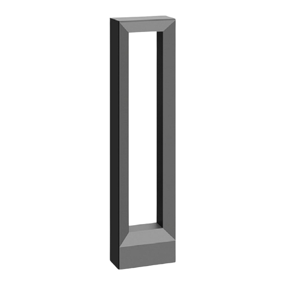
Bollard - Adjustable
Dimensions
A: 10-5/8
B: 43-3/8
C: 5-1/2
Figure 1:
Lichttechnik
Light technique
Eine innenliegende Verstelleinrichtung
An internal adjusting device allows you to
ermöglicht die Einstellbarkeit des optischen
adjust the optical system of the luminaire.
Systems der Leuchte.
In this way, symmetrical light distribution can be
So können eine symmetrische
achieved with the same proportions of light or
Lichtstärkeverteilung mit gleichen Lichtanteilen
with different, asymmetrical light distribution.
oder unterschiedliche asymmetrische
Lichtstärkeverhältnisse erzeugt werden.
Figure 3:
0°
15°
Einstellung der Ausstrahlrichtung:
Adjustment of the light radiation:
Einstellung werkseitig 0°.
Joint ajustment is factory-set at 0°.
Für Einstellung 15° oder 30°:
For adjustment 15° or 30°:
Innensechskantschrauben (SW 4) im
Undo hexagon socket head screws (wrench
Leuchtenkopf lösen und Deckel mit
size 4 mm) in the luminaire top and lift off cover
Verstelleinrichtung abheben.
with adjusting device.
Innensechskantschrauben (SW 3) auf beiden
Loosen the hexagon socket screws (wrench
Seiten der Verstelleinrichtung lösen und
size 3 mm) on both sides of the adjusting
gewünschte Ausstrahlrichtung einstellen.
device and set the desired beam direction.
Innensechskantschrauben fest anziehen.
Tighten the hexagon socket screws.
Deckel im Leuchtengehäuse einsetzen und
Insert the cover into the luminaire housing and
Schrauben gleichmäßig fest anziehen.
tighten the screws evenly.
Figure 4:
Überspannungsschutz
Overvoltage protection
The electronic components installed in the
Die in der Leuchte verbauten elektronischen
Komponenten sind nach DIN EN 61547 gegen
luminaire are protected against overvoltage in
Überspannung geschützt.
accordance with DIN EN 61547.
Maintenance:
Um einen zusätzlichen Schutz z. B. vor
To achieve an additional protection against
Transienten etc. zu erreichen, empfehlen wir
e. g. transients, etc. we recommend separate
Clean regularly with solvent-free cleaner
separate Überspannungsschutzkomponenten.
overvoltage protection components.
Sie finden diese auf unserer Website unter
You can find them on our website at
removing dirt and debris. Do not use high
www.bega.com.
www.bega.com.
pressure cleaners.
The ideal protection of all electronic
Den optimalen Schutz aller in den Leuchten
verbauten elektronischen Komponenten
components installed in the luminaires is
erreichen Sie durch die Verwendung von
achieved by using bounce-free switching
prellfreien Schaltkontakten wie einem
contacts such as an electronic relay (solid-state
elektronischen Relais, (solid-state-relais), z. B.
relay), e.g. BEGA 71 320.
BEGA 71 320.
Reinigung · Pflege
Cleaning · Maintenance
Leuchte regelmäßig mit lösungsmittelfreien
Clean luminaire regularly with solvent-free
Reinigungsmitteln von Schmutz und
cleansers from dirt and deposits.
Ablagerungen säubern.
Do not use high pressure cleaners.
Dafür keinen Hochdruckreiniger verwenden.
Replacement Parts
Bitte beachten Sie:
Please note:
See label inside of fixture for LED replacement
Den im Leuchtengehäuse befindlichen
Do not remove the desiccant bag from the
Trockenmittelbeutel nicht entfernen.
luminaire housing.
part number.
Er dient zur Aufnahme von Restfeuchtigkeit.
It is needed to remove residual moisture.
Consult factory for all other replacement
components.
BEGA Gantenbrink-Leuchten KG · Postfach 31 60 · 58689 Menden · info@bega.com · www.bega.com
88 062
Figure 2:
Technique d'éclairage
Un dispositif de réglage intégré permet
l'ajustement du système optique du luminaire.
On peut ainsi obtenir une répartition lumineuse
symétrique avec un éclairement uniforme
ou bien diverses intensités lumineuses
asymétriques
30°
Réglage de la direction du faisceau :
Réglage de la rotule à l'usine 0°.
Pour réglage 15° ou 30° :
Desserrer les vis à six pans creux (taille de
clé 4) de la lête du luminaire et soulever le
couvercle avec le dispositif de réglage.
Desserrer les vis à six pans creux (taille de
clé 3) se trouvant de chaque côté du dispositif
de réglage puis régler la direction du faisceau
souhaitée. Serrer fermement les vis à six pans
creux.
Remettre en place le couvercle dans le
boîtier du luminaire puis serrer fermement et
régulièrement les vis.
SW 3
Protection contre les surtensions
Les composants électroniques installés dans
le luminaire sont protégés contre la surtension
conformément à la norme DIN EN 61547.
Pour obtenir une protection supplémentaire
contre la surtension, les tensions transitoires
etc., nous proposons des composants de
protection séparés. Vous les trouverez sur notre
site web www.bega.com.
Pour garantir la protection optimale de tous
les composants électroniques installés dans
les luminaires, il faut utiliser des contacts de
commutation sans rebond tel qu'un relais
électronique, (solid-state-relais) par ex. BEGA
71 320.
Nettoyage · Entretien
Nettoyer régulièrement le luminaire des
dépôts et des souillures avec des produits de
nettoyage ne contenant pas de solvants.
Ne pas utiliser de nettoyeur haute pression.
Attention :
Ne pas retirer le sachet de dessicant présent
dans l'armature du luminaire.
Il sert à absorber l'humidité résiduelle.
Updated: 06/06/24
88 062
1 of 2
3 / 4
Advertisement

Related Manuals for BEGA 88 062


Summary of Contents for BEGA 88 062
- Page 1 1 of 2 Due to the dynamic nature of lighting products and the associated technologies, luminaire data on this sheet is subject to change at the discretion of BEGA North America. For the most current technical data, please refer to bega-us.com...
- Page 2 2 of 2 Due to the dynamic nature of lighting products and the associated technologies, luminaire data on this sheet is subject to change at the discretion of BEGA North America. For the most current technical data, please refer to bega-us.com...
Need help?
Do you have a question about the 88 062 and is the answer not in the manual?
Questions and answers