
Related Manuals for HTW MINI V10 B


Summary of Contents for HTW MINI V10 B
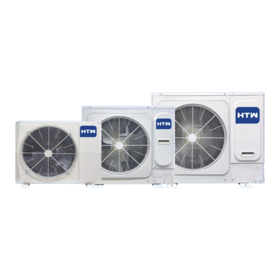
- Page 1 MINI V10 B HTW-VED10ILMV10B HTW-VED12ILMV10B HTW-VED14ILMV10B HTW-VED16ILMV10B ENGLISH Owner’s and installation manual. Mini VRF Outdoor Unit + info Please, read carefully this manual before using the product Thank you...
-
Page 3: Table Of Contents
CONTENTS OPERATION MANUAL BEFORE OPERATING OPERATION MAINTENANCE AND REPAIR TROUBLESHOOTING CHANGE INSTALLATION SITE DISPOSAL INSTALLATION MANUAL PRECAUTIONS ABOUT THE PACKING BOX ABOUT THE OUTDOOR UNIT PREPARATIONS BEFORE INSTALLATION OUTDOOR UNIT INSTALLATION ELECTRICAL WIRING CONFIGURATION TEST RUNNING PRECAUTIONS ON REFRIGERANT LEAKAGE TURN OVER TO CUSTOMER... - Page 4 Air inlet Air outlet Refrigerant pipe connector Mounting bracket NOTE All the pictures in this manual are for explanation purpose only. They may be slightly different from the air conditioner you purchased (depend on model). The actual shape shall prevail. The units 8-18 kW comply with IEC 61000-3-12.
-
Page 5: Operation Manual
Never replace a fuse with that of wrong rated current or other OPERATION MANUAL wires when a fuse blows out. Use of wire or copper wire may cause the unit to break down or cause a fire. 1. BEFORE OPERATING It is not good for your health to expose your body to the air flow To prevent injury to the user or other people and property for a long time. -
Page 6: Operation
2. OPERATION Do not operate the air conditioner with a wet hand. An electric shock may happen. 2.1 Operation range Do not touch the heat exchanger fins. Use the system in the following temperature for safe and effective These fins are sharp and could result in cutting injuries. operation. -
Page 7: Maintenance And Repair
When the protection equipment is activated, the operation When the cooling and heating operation conflict with each other, the indicator still lights while the air conditioner is not running. But the check indoor unit which are running in cooling or fan mode would stop and there will be standby or no priority displayed on the control panel. -
Page 8: Troubleshooting
Clean the air filter and external shell of the unit. Please contact the WARNING installation or maintenance personnel. The installation/operation manual of the indoor unit includes maintenance tips and cleaning Do not attempt to modify, dismantle, remove, reinstall or repair procedures. - Page 9 Table 4 -1 Symptoms Causes Solution Power failure. Wait for the comeback of power. Power switch is off. Switch on the power. Fuse of power switch may have burned. ReplLocation: Unit does not start Unit does not start Batteries of remote controller exhausted Replace the batterises or check the or other problem of controller.
- Page 10 4.2 Troubles and causes of remote controller Before asking for serving or repairing , check the following points. (see in Table 4-2) Table 4-2 Symptoms Causes Solution When the automatic mode is selected, Check whether the MODE indicated the air conditioner will automatically on the display is "AUTO".
- Page 11 4.3 Error code: Overview Table 4-3 (8/10/12/14/16 kW) Recovery mode Error code Fault or protection type Recoverable Communication fault between main control board and communication terminals block Recoverable Communication error between indoor and outdoor unit Recoverable Outdoor heat exchanger temperature sensor (T3) error or outdoor ambient temperature sensor (T4) error Recoverable Input voltage protection...
- Page 12 Table 4-4 (18 kW) Recovery mode Error code Fault or protection type Recoverable Communication error between main chip and compressor drive chip Recoverable Communication error between indoor and outdoor units Recoverable Actual compressor frequency differs from target frequency by more than 15Hz protection Recoverable Abnormal power supply voltage Recoverable...
-
Page 13: Change Installation Site
Symptom 4.3: Outdoor unit 4.4 Following symptoms are not air conditioner troubles When the tone of operating noise changes, the noise is caused by the change of frequency. Symptom 1: The system does not operate Symptom 5: Dust comes out of the unit The air conditioner does not start immediately after the ON/OFF button on the romote controller is pressed. -
Page 14: Installation Manual
The temperature of refrigerant circuit will be high, please keep INSTALLATION MANUAL the interconnection cable away from the copper tube. An all-pole disconnection device which has at least 3mm separation distance in all pole and a residual current device (RCD) with the rating of above 10mA shall be incorporated in 1. -
Page 15: About The Packing Box
2.2 Attached fittings Be sure to provide grounding. Do not connect ground wires to gas pipes, water pipes, lightning rods or ground wires for telephone cables. NAME SHAPE QUANTITY Conform to the regulations of the local electric company when wiring the power supply. 1. -
Page 16: Preparations Before Installation
CAUTION CAUTION The total capacity of the IDUs, measured in horsepower, must not Install the outdoor unit at a place where discharge air is not blocked. exceed 130% of the capacity of the ODU. When the combination When an outdoor unit is installed in a place that is always exposed ratio of IDUs exceeds 100%, the output capacity of the system to a strong wind like a coast or on a high story of a building, secure may decrease. - Page 17 12/14/16 kW Table 4-1(unit:mm) Model 8/10 12/14/16 1040 1053 Drawing No. Fig.4-2,Fig.4-3 Fig.4-4,Fig.4-5 Fig.4-6,Fig.4-7 Fig.4-4 Single unit installation (Wall or obstacle) Air inlet surface > 300 > 300 Maintenance cable and pipeline surface Air inlet surface > 600 Fig.4-5 > 2000 Air outlet surface 18 kW Fig.4-8...
- Page 18 The first connect methond CAUTION Outdoor Unit Keep a distance of 2000mm or more between the unit and the wall surface when the discharge port faces to the wall of the building. 2000 Fig. 4-11 The First Line Branch Pipe The second connect methond Outdoor Unit(Take Model 160 for example) Fig.4-10...
- Page 19 When the outdoor unit connects only one indoor unit Table 4-4 The main pipes diameters of indoor unit Table 4-6 The max height drop(m) Indoor unit main The length of Total capactiy of MODEL The number pipe size(mm) refrigerant the downstream Branch Pipe (kW) of bends...
-
Page 20: Outdoor Unit Installation
5. OUTDOOR UNIT INSTALLATION NOTE 5.1 Prepare structure for installation Material: Only seamless phosphorus-deoxidized copper piping that complies with all applicable legislation should be used. Make concrete foundation according to the sepecifications of Thicknesses: Temper grades and minimum thicknesses for the outdoor units.(refer to Fig.5-1) different diameters of piping should comply with local regulations. - Page 21 Outlet piping connection mode Liquid side Gas side stop valve stop valve Gas side Liquid side stop valve stop valve Liquid side piping Gas side piping (provided on site) (provided on site) Fig.5-3 Fig.5-7 The connection method of flaring Back outlet piping connection mode Gas side piping (provided on site) Back out...
- Page 22 Outlet piping connection mode Outlet piping connection mode Liquid side Liquid side stop valve stop valve Gas side Gas side stop valve stop valve Liquid side piping Liquid side piping Gas side piping Gas side piping (provided on site) (provided on site) (provided on site) (provided on site) Fig.5-15...
- Page 23 5.4 Leak Detection 5.6 Airtight Test Use soapy water or a leak detector to check whether air leaks at each joint. Air tightness test – nitrogen must be used. A and B indicate check valves of ODU. Increase the pressure from the liquid pipe and gas pipe to 4.0 MPa at C and D indicate IDU connecting pipe ports.
-
Page 24: Electrical Wiring
5.8 Refrigerant Amount to be Added Calculate the amount of the R410A refrigerant to be added based on the diameter and length of the liquid pipes of the ODU and IDUs. Table 5-1 Additional refrigerant charge per Liquid Piping meter of equivalent length of Diameter liquid piping (kg) (mm OD) - Page 25 CAUTION CAUTION Please select power source for indoor unit and outdoor unit The reserved function is indicated in broken line table, users can respectively. select it when necessary. The power supply has specified branch circuit with leakage protector and manual switch. Indoor/Outdoor Unit Signal Wire The outdoor unit model which corresponding to different outdoor unit power supply should refer to the nameplate.
- Page 26 Wiring Terminal Description Note: The wired controller and centralized controller in the dashed box are optional accessories. If necessary, please contact the local distributor for purchase. Centralized controller P Q E X Y E X Y E Suspend Please use the shielded wire, and the shield layer must be grounded. P Q E P Q E P Q E...
-
Page 27: Configuration
Single phase indoor unit CAUTION 1. Refrigerant piping system, indoor unit-indoor unit connection Display signal wires and indoor unit-outdoor unit connection signal wire board are in the same system. 2. When power cord is parallel with signal wire, please put them X Y E into separate wire distribution pipes, and leave a proper distance. -
Page 28: Test Running
8. TEST RUNNING Display function The ODU check board or the main control board is equipped with Operate according to "gist for test running" on the electric control box the check button (SW2 for 8/10/12/14/16/18 kW). The digital tubes cover. on the check board or the main control board will show the parameters of the air conditioner in the following order (the button CAUTION... -
Page 29: Precautions On Refrigerant Leakage
9.1 Important information for the used 9. PRECAUTIONS ON REFRIGERANT refrigerant LEAKAGE This product has the fluorinated gas, it is forbidden to release to air. Refrigerant type: R410A; Value of GWP: 2088; This air conditioner (A/C) adopts inncouous and nonflammable GWP=Global Warming Potential refrigerant. - Page 31 España info@htwspain.com France info@htwfrance.com Portugal info@htw.pt Italy info.it@htwspain.com C. Can Cabanyes, 88 08403 Granollers (Barcelona) - España España sat@groupgia.com tel. +34 933904220 tel. +34 93 390 42 20 France sat.fr@groupgia.com tel. +33 465430168 info@htwspain.com Portugal sat.pt@groupgia.com www.htwspain.com Italy sat.it@groupgia.com tel. +39 05641715509 IMPORTANT INFORMATION FOR CORRECT DISPOSAL OF THE PRODUCT IN ACCORDANCE WITH EC DIRECTIVE 2002/96/EC.
Need help?
Do you have a question about the MINI V10 B and is the answer not in the manual?
Questions and answers