Table of Contents
Advertisement
2024 Lennox Industries Inc.
©
Dallas, Texas, USA
General .....................................................................................1
Included Parts...........................................................................2
Model Number Identification .....................................................3
Indoor / Outdoor Unit Match-Ups..............................................4
System Dimensions ..................................................................5
Outdoor Units ................................................................................................... 5
Indoor Units ...................................................................................................... 8
Wall Mounting Plates ........................................................................................ 9
System Clearances ................................................................11
Outdoor Unit ................................................................................................... 11
Indoor Unit ...................................................................................................... 11
Torque Requirements for Caps and Fasteners.......................12
Indoor Unit Installation ............................................................12
Unit Placement Considerations ...................................................................... 12
Determining Wall Mounting Plate Location .................................................... 12
Installation of Wall Mounting Plate ................................................................. 13
Installation of Wall Sleeve .............................................................................. 13
Installation of Indoor Unit on Wall Mounting Plate .......................................... 13
Indoor Unit Condensate Piping Connections ................................................. 14
Outdoor Unit Installation .........................................................14
Placement Considerations ............................................................................. 14
Direct Sunlight, Rain, Snow and Ice Protection .............................................. 15
Prevailing Winds ............................................................................................. 16
Buried Refrigerant Pipe Protection ................................................................. 16
Outdoor Unit Condensate Piping .................................................................... 16
Securing the Outdoor Unit .............................................................................. 17
Refrigerant Piping Connections ..............................................17
Leak Test and Evacuation ......................................................19
Leak Test ........................................................................................................ 19
Triple Evacuation Procedure .......................................................................... 20
Wiring Connections ................................................................20
Outdoor Unit .................................................................................................. 20
Indoor Unit ...................................................................................................... 20
Unit Start-Up ...........................................................................28
Adding Refrigerant for Longer Line Set ..................................29
Troubleshooting ......................................................................29
I-Clean Feature.......................................................................30
Test Run .................................................................................31
Pre-Checks ..................................................................................................... 31
Procedure ....................................................................................................... 31
Double-Check Pipe Connections ................................................................... 31
If Ambient Temperature is below 60°F (16°C) ................................................ 31
Dry Mode Operation (Dehumidification) .................................31
Procedure ....................................................................................................... 31
Sequence of Operation .................................................................................. 31
Humidity Control .....................................................................32
Intelligent Eye Function .........................................................32
INSTALLATION
INSTRUCTIONS
MLB/MPC Outdoor Units
with MWMC Indoor Units
SINGLE-ZONE MINI-SPLIT SYSTEMS
(115V and 208/230V) --
Wall-Mounted Indoor Unit
507545-07 04/2024
Supersedes 02/2024
THIS MANUAL MUST BE LEFT WITH THE OWNER
FOR FUTURE REFERENCE
WARNING
Improper installation, adjustment, alteration, ser vice or
maintenance can cause property damage, personal
injury or loss of life.
Installation and service must be performed by a li censed
professional HVAC installer (or equivalent) or a service
agency.
WARNING
The clean Air Act of 1990 bans the intentional venting of
refrigerant (CFCs, HCFCs, and HFCs) as of July, 1992.
Approved methods of recovery, recycling or reclaiming
must be followed. Fines and/or incarceration may be
levied for non-compliance.
CAUTION
As with any mechanical equipment, contact with sharp
sheet metal edges can result in personal injury. Take
care while handling this equipment and wear gloves and
protective clothing.
General
These instructions are intended as a general guide and
do not supersede local or national codes in any way.
Authorities having jurisdiction should be consulted before
installation.
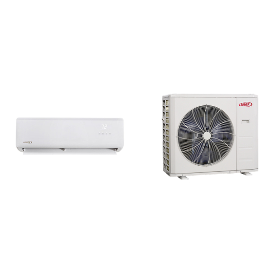
The MWMC wall-mounted indoor units are matched with
an outdoor heat pump unit to create a mini-split system
that uses HFC-410A refrigerant.
Advertisement
Table of Contents

Related Manuals for Lennox MLB Series


Summary of Contents for Lennox MLB Series
-
Page 1: Table Of Contents
INSTALLATION INSTRUCTIONS 2024 Lennox Industries Inc. © MLB/MPC Outdoor Units Dallas, Texas, USA with MWMC Indoor Units SINGLE-ZONE MINI-SPLIT SYSTEMS (115V and 208/230V) -- Wall-Mounted Indoor Unit 507545-07 04/2024 Supersedes 02/2024 Table of Contents THIS MANUAL MUST BE LEFT WITH THE OWNER FOR FUTURE REFERENCE General ..................1... -
Page 2: Included Parts
Included Parts Package 1 of 1 contains the following: 1 - Assembled Indoor Unit The assembled indoor unit will include the following items: Parts Figure Quantity Parts Figure Quantity M0STAT60Q-1 Installation and owner’s 1 ea. Wireless controller manual Wireless control BUBBLE LEVEL holder with 2 mounting... -
Page 3: Model Number Identification
Model Number Identification OUTDOOR SINGLE ZONE HEAT PUMP UNITS M P C 009 S 4 S - 1 P Series Type Voltage M = Mini-Split L = 115V-1 phase-60hz P = 208/230V-1 phase-60hz Unit Type Minor Design Sequence L = Low Ambient Heat Pump P = Heat Pump 1 = 1st Revision Refrigerant Circuits... -
Page 4: Indoor / Outdoor Unit Match-Ups
Indoor / Outdoor Unit Match-Ups Table 1. Unit Match-Ups Outdoor Unit Indoor Unit Voltage MPC012S4S-*L MWMC12S4-*L 115V MWMC006S4-*P 208/230V MPC009S4S-*P MWMC009S4-*P 208/230V MPC012S4S-*P MWMC012S4-*P 208/230V MPC018S4S-*P MWMC018S4-*P 208/230V MPC024S4S-*P MWMC024S4-*P 208/230V MPC030S4S-*P MWMC030S4-*P 208/230V MLB009S4S-*P MWMC009S4-3P 208/230V MLB012S4S-*P MWMC012S4-3P 208/230V MLB018S4S-*P MWMC018S4-2P 208/230V... -
Page 5: System Dimensions
System Dimensions Outdoor Units DRAIN HOLE (Bottom of Unit) 3/8 (10) 1-1/2 (62) 3/4 (19) 11-1/4 3 (76) (286) 12-3/8 (314) TOP VIEW 30-7/8 (784) 21-7/8 GAS VALVE (556) LIQUID VALVE 2-3/8 (60) 3-3/4 (95) 17-3/4 (451) 11-7/8 (302) 30-1/8 (765) 32-7/8 (835) SIDE VIEW FRONT VIEW... - Page 6 DRAIN HOLE (Bottom of Unit) ?? (??) 1/2 (13) ?? (??) 13-3/4 12-3/4 (349) (324) (381) ?? (??) ?? (??) 2-7/8 (73) TOP VIEW 35-1/4 (895) 26-1/2 GAS VALVE (673) LIQUID VALVE 2-3/8 (60) 4-1/4 (108) 26-1/8 (664) 13-1/2 (343) 35 (889) SIDE VIEW 37-5/8 955)
- Page 7 DRAIN HOLE (Bottom of Unit) 1 (25) 17-3/4 (450) 1-7/8 (48) 12-1/2 (318) 12-1/8 (308) 13-5/8 (346) 1-1/2 (32) TOP VIEW 32 (813) GAS VALVE 21-7/8 (556) LIQUID VALVE 2-3/8 (60) 3-3/4 (95) 20-1/8 (511) 31-3/4 (806) 13 (330) 34-3/8 (873) FRONT VIEW SIDE VIEW Figure 5.
-
Page 8: Indoor Units
DRAIN HOLE (Bottom of Unit) 18-1/8 (460) 3-5/8 (92) 15-7/8 (403) 15-1/4 (387) (457) 1 (25) 2-7/8 (73) TOP VIEW 40-1/2 (1029) 31-7/8 (810) GAS VALVE LIQUID VALVE 2-3/8 (60) 4-1/4 (108) 26-1/2 (673) 16-1/8 (410) SIDE VIEW 37-1/4 (946) FRONT VIEW Figure 7. -
Page 9: Wall Mounting Plates
Wall Mounting Plates Indoor unit outline (51) 4-3/4 (51) (121) 1-5/8 1-5/8 (41) (41) Left rear side Right rear side refrigerant pipe inlet refrigerant pipe inlet 2-1/2 (64) diameter 2-1/2 (64) diameter Size MWMC006, 009 11-1/2 28-1/2 13-3/4 MWMC012 11-3/4 31-3/4 15-7/8 Figure 8. - Page 10 Indoor unit outline 22-1/2 (570) 2-3/8 (60) BUBBLE LEVEL 14-5/8 (371) inch LIQUID 2-3/4 inch (51) RECOMMAND (70) 2 (51) 2 (51) 44-7/8 (1140) Left rear side Right rear side refrigerant pipe inlet refrigerant pipe inlet 2-1/2 (64) diameter 2-1/2 (64) diameter Figure 10.
-
Page 11: System Clearances
System Clearances Outdoor Unit 24 (610) Air Inlet (305) (305) (610) (2007) Air Outlet Minimum rear clearance can be 6 inches (152 mm) when mounted on brackets and with no obstructions on the other three sides. Figure 11. Outdoor Unit Clearances - Inches (mm) Indoor Unit Ceiling 6”... -
Page 12: Torque Requirements For Caps And Fasteners
See the Lennox Service and Application Notes C-08-1 for further details and information. Determining Wall Mounting Plate Location Table 3. Torque Requirements... -
Page 13: Installation Of Wall Mounting Plate
Installation of Wall Mounting Plate INSIDE Install the wall mounting plate (see “Figure 9. MWMC018S4S Indoor Unit Wall Plate Dimensions - Inches (mm)” on page OUTSIDE Typical 9) so that it is correctly positioned horizontally and installation vertically. The indoor unit must be installed level on the procedure wall to allow proper condensate drainage. -
Page 14: Indoor Unit Condensate Piping Connections
Indoor Unit Condensate Piping Connections Placement Considerations Consider the following when positioning the unit: IMPORTANT • In coastal areas or other places with salty atmosphere of sulfate gas, corrosion may shorten the life of the Make sure that drain piping is properly routed and unit. -
Page 15: Direct Sunlight, Rain, Snow And Ice Protection
Direct Sunlight, Rain, Snow and Ice Protection • If the outdoor unit is subjected to prolong exposure to direct sunlight with temperatures over 100°F (38°C) a canopy is recommended as illustrated in “Figure 19. Air Inlet Outdoor Unit on Pedestal and Protective Canopy” or “Figure 24. -
Page 16: Prevailing Winds
Prevailing Winds Normally wind baffles are not required for a outdoor unit. However, in order to maximize reliability and performance, the following best practices should be followed. If unit coil cannot be installed away from prevailing winter winds, some method of protecting the coil is recommended. 24 in 610 mm 12 in... -
Page 17: Securing The Outdoor Unit
Securing the Outdoor Unit Slab or Roof Mounting Install the unit a minimum of 4 inches (102 mm) above the roof or ground surface to avoid ice build-up around the 6 in 152 mm unit. Place the unit above a load bearing wall or area of the roof that can adequately support the unit. - Page 18 Table 4. Flaring Piping Table 5. Refrigerant Piping and Indoor Unit Connection Sizes Flare Dimension A (mm) Size Liquid Line Suction Line Pipe Diameter Flare Shape (Btuh) 6000, 9000 1/4” (6.35) 90 ° 4 12000 3/8” (9.62) 12.0 12.4 18000 1/2”...
-
Page 19: Leak Test And Evacuation
Table 7. Refrigerant Line Set Requirements Minimum Line Set Length - 10 ft. (3m) Maximum Line Set OUTDOOR UNIT INDOOR UNIT Length Maximum Line Set Length Maximum Maximum Elevation - Elevation - INDOOR UNIT Outdooor Outdooor Unit BELOW Unit ABOVE Indoor Unit Indoor Unit OUTDOOR UNIT... -
Page 20: Triple Evacuation Procedure
Indoor Unit IMPORTANT • All indoor units are powered by the outdoor unit Use only oxygen-free nitrogen (OFN). • Communication Wiring (Indoor Units 30K and Below): Use one stranded 4-conductor wire to provide power Triple Evacuation Procedure and communication A Micron or Torr gauge must be used for this procedure. •... - Page 21 IMPORTANT This unit must be properly grounded and protected by a circuit breaker. The ground wire for the unit must not be connected to a gas or water pipe, a lightning conductor or a telephone ground wire. Do not connect power wires to the outdoor unit until all other wiring and piping connections have been completed. Do not install the unit near a lighting appliance that includes a ballast.
- Page 22 Table 9. Single Zone Mini-Split Wiring Guide Wire Gauge / MOCP System Number of Systems System Voltage Wire Type Capacity Conductors MCA / Max Fuse Indoor to Outdoor Wiring (Power only) 208/230 VAC Stranded 14AWG*3 Stranded, unshielded L1, L2 and GND Indoor to Outdoor Wiring Stranded 208/230 VAC...
- Page 23 HORIZONTAL INDOOR WIRING DIAGRAM DC FAN SWING MOTOR M MOTOR 5(10) Output:310VDC CN12 Output: CN19 L-OUT (or 140VDC) 12VDC VERTICAL Input:230VAC Output: SWING MOTOR (or 115VAC) 12VDC CN22 L-IN(or CN 2) BLUE(BLACK) MAIN CONTROL BOARD N-IN Input:230VAC CN15 (or 115VAC) YELLOW Output: INDOOR COIL...
- Page 24 WIRING DIAGRAM I NDOOR UNI T POWER SUPPLY (T5) BL UE CN17 CN15 CN3 CN2 CN1 CN16 C R AN KC ASE EARTH L-IN N-IN H EAT ER H EAT ER CN1A MA I N BOARD CN50 CN31 DC FAN CN1A I NPUT 230V CN31 OUTPUT 0~12V DC...
- Page 25 WIRING DIAGRAM INDOOR UNIT POWER SUPPLY T3 T4 BLUE CN16 CN19 CN17 CN6 CN8 CN7 CN2 EARTH L-IN N-IN T.M.P_Sensor MAIN BOARD CN18 DC FAN CN2 7/8 INPUT 230V CN18 OUTPUT 0~12V DC CN414 OUTPUT 0~310V AC CN60 OUTPUT 230V CN17 OUTPUT 0~5V CN16...
- Page 26 Figure 39. 208/230V MPC030S4S-*P Outdoor Unit Wiring Diagram WIRING DIAGRAM INDOOR UNIT POWER SUPPLY BLUE CN17 CN15 CN3 CN2 CN1 CN16 C R AN KC ASE EARTH L-IN N-IN H EAT ER H EAT ER CN1A MAIN BOARD CN50 CN31 DC FAN CN1A INPUT 230V...
- Page 27 WIRING DIAGRAM I NDOOR UNI T POWER SUPPLY T3 T4 BL UE CN16 CN19 CN17 CN6 CN8 CN7 CN2 C R AN KC ASE EARTH L-IN N-IN T.M .P_Sensor 4- WAY H EAT ER H EAT ER MA I N BOARD CN18 DC FAN CN2 7/8 I NPUT...
-
Page 28: Unit Start-Up
NOT AVAILABLE ON 24K NOT AVAILABL E ON 24K U~V~W among phases 0~250VAC Output:0-12VDC Connect to FAN Input:0-5VDC voltage among phases 0~200VAC Output:230 VAC Output:230 VAC Intput:230 VAC Output:230 VAC Output:230 VAC CODE Figure 42. 208/230V MLB024S4S-*P Outdoor Unit Wiring Diagram in “Table 3. -
Page 29: Adding Refrigerant For Longer Line Set
Adding Refrigerant for Longer Line Set Table 11. Indoor Unit Error and Status Code Display The outdoor unit is factory-charged with refrigerant. Display Type Information Calculate the additional refrigerant required according to the diameter and the length of the liquid pipe between the Outdoor ambient temperature sensor T4 is in outdoor unit and indoor unit connections. -
Page 30: I-Clean Feature
I-Clean Feature For units that use the provided wireless remote control, there is a button labeled “i-clean”. Press to activate self cleaning mode. In cooling or dry mode only, the indoor unit will temporarily change operation to allow condensate on the indoor unit coil to evaporate, and then will turn off. -
Page 31: Test Run
2. Using insulation tape, wrap the indoor refrigerant pipe Test Run connections that you left uncovered during the indoor unit installation process. Pre-Checks If Ambient Temperature is below 60°F (16°C) Only perform test run after you have completed the You cannot use the remote controller to turn on the following steps: COOL function when the ambient temperature is below •... -
Page 32: Humidity Control
Humidity Control The user can adjust the room humidity during Dry operation. The humidity range adjustment has a range of 35%~85%. There is a humidity button on the wireless remote, press that button to increase the humidity in 5% increments. Intelligent Eye Function With the Intelligent Eye Function, your indoor unit will automatically detect the room vacant and adjust the...
Need help?
Do you have a question about the MLB Series and is the answer not in the manual?
Questions and answers
What do I do if a dF error appears?
If a dF error appears on a Lennox MLB Series unit, it indicates a Defrost Status. This is not an error but a normal operating status. No action is needed.
This answer is automatically generated
lennox heat pump 6924e01263 mwmc009s4-2p Will this unit work in -28C?