Table of Contents
Advertisement
Quick Links
Installation, Kit
Control Board Replacement
Kit
For replacement of control board in XT sprayers. For professional use only.
Not approved for use in explosive atmospheres or hazardous (classified) locations.
Models: 20B426, 20B427, 20B428, 2002367
Important Safety Instructions
Read all warnings and instructions in this
manual and the sprayer manual before
using the equipment. Be familiar with the
proper control and usage of the
equipment. Save these instructions.
Related Manuals
Find English manuals and any available translations at
www.graco.com.
English Manual
Description
Number
3A9095
Sprayer Operation Manual
3B0142A
EN
Advertisement
Table of Contents

Subscribe to Our Youtube Channel
Related Manuals for Graco 20B426


Summary of Contents for Graco 20B426
- Page 1 3B0142A For replacement of control board in XT sprayers. For professional use only. Not approved for use in explosive atmospheres or hazardous (classified) locations. Models: 20B426, 20B427, 20B428, 2002367 Important Safety Instructions Read all warnings and instructions in this manual and the sprayer manual before using the equipment.
-
Page 2: Table Of Contents
Installation....... . . 5 Graco Standard Warranty....13 Disassembly. -
Page 3: Safety Symbols
Safety Symbols Safety Symbols The following safety symbols appear throughout this manual and on warning labels. Read the table below to understand what each symbol means. Symbol Meaning Electric Shock Hazard Moving Parts Hazard Ground Equipment Read Manual Follow Pressure Relief Procedure Wear Personal Protective Equipment Safety Alert Symbol... -
Page 4: General Warnings
General Warnings General Warnings The following warnings apply throughout this manual. Read, understand, and follow the warnings before using this equipment. Failure to follow these warnings can result in serious injury. WARNING ELECTRIC SHOCK HAZARD This equipment must be grounded. Improper grounding, setup, or usage of the system can cause electric shock. -
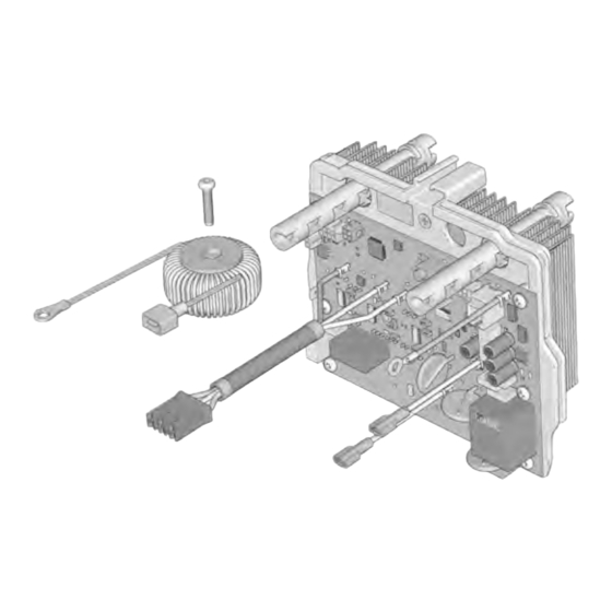
Page 5: Installation
Installation Installation 5. Remove two screws (34) using a T20 torx tool. Remove top cover (39). Keep clear of electrical and moving parts during repair procedure. To avoid electrical shock hazards, wait five minutes after disconnecting power cord for stored electricity to dissipate before starting repair procedure. -
Page 6: Assembly
Installation Assembly 5. Install top cover (39). Ensure tabs on the inside of the top shroud and align with the grooves on the control board assemble as shown. Install two 1. Perform the Pressure Relief Procedure found in screws (34) and torque to 12-16 in-lbs. (1.3-1.8 the sprayer manual. -
Page 7: Transducer Calibration
Installation Knob Calibration 7. Install front cover (43) with four screws (11) and torque to 20-25 in-lbs. (2.2-2.8 N•m). NOTE: Knob calibration should be performed whenever the control board is replaced. 1. To perform knob calibration, enter secondary menu by holding menu button while powering sprayer. 2. -
Page 8: Disassembly Instructions For Kit #20B426
Installation Disassembly Instructions for Kit Installation Instructions for Kit #20B426 #20B426 1. Complete steps 1-5 of Disassembly, page 5. 4. Install new filter (24) and screw (25) Torque to 12-16 in-lbs. (1.3-1.8 N•m). Plug ground with from cord 2. Remove the ground screw (73) from the back of the into the filter. -
Page 9: Wiring Diagrams
Wiring Diagrams Wiring Diagrams 110-120V 3B0142A... -
Page 10: 220-240V
Wiring Diagrams 220-240V 3B0142A... -
Page 11: 110Uk
Wiring Diagrams 110UK 3B0142A... -
Page 12: California Proposition 65
California Proposition 65 California Proposition 65 CALIFORNIA RESIDENTS WARNING: Cancer and reproductive harm – www.P65warnings.ca.gov. 3B0142A... -
Page 13: Graco Standard Warranty
With the exception of any special, extended, or limited warranty published by Graco, Graco will, for a period of twelve months from the date of sale, repair or replace any part of the equipment determined by Graco to be defective. - Page 14 Original instructions. This manual contains English. MM 3B0142 Graco Headquarters: Minneapolis International Offices: Belgium, China, Japan, Korea GRACO INC. AND SUBSIDIARIES • P.O. BOX 1441 • MINNEAPOLIS MN 55440-1441 • USA Copyright 2024, Graco Inc. All Graco manufacturing locations are registered to ISO 9001. www.graco.com...
Need help?
Do you have a question about the 20B426 and is the answer not in the manual?
Questions and answers