Midland 5001z - CB Radio Manual
- Owner's manual (14 pages) ,
- Owner's manual (14 pages)
Advertisement
- 1 Welcome to the World of Midland Electronics
- 2 Major 5001z Features
- 3 Installation
- 4 CB Antenna
- 5 5001z Front Panel Features and Operation
- 6 How to Operate your Transceiver
- 7 Back Panel Features and Operation
- 8 How to Operate the Public Address
- 9 Technical Specifications
- 10 Service and Technical Support
- 11 Documents / Resources
Welcome to the World of Midland Electronics
In the years ahead, you can expect to realize time and again why Midland holds the front running position among CB users everywhere. You will come to know that American Original is not just a slogan, but the heading of long list of hearable, seeable benefits. As your Midland CB experience unfolds and grows we hope you will remember that CB radios are only one kind of electronic excellence available under the Midland name.
Your 40 channel CB radio represents the state of the art in high tech engineering. The unit incorporates microprocessor controlled PLL circuitry for precise tuning.
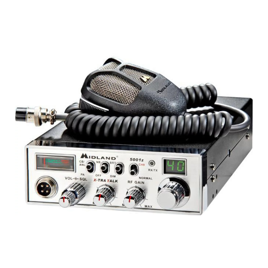
The 5001z is a classic style CB that is skillfully constructed with the finest components.
This radio is designed for reliable and trouble-free performance for years to come. Enjoy!
Major 5001z Features
- 40 CB Channels
- 4 Watt Output Power
- X-TRA TALK Mic Gain
- 4- Pin Front Panel Mic Connector
- PA Function
- Switchable Noise Blanker(NB)
- Instant Channel 9
- Dimmer Control
- RF Gain
- Automatic Noise Limiter(ANL)
- Push to talk ergonomically designed microphone
- 9 ft coil Mic cord
- Includes mounting bracket/hardware and fused DC power cord
Installation
This transceiver may be installed in any 12-volt negative ground-system car or truck. Most current U.S. and foreign vehicles use a negative system, but some older models and some newer large trucks may have a positive ground. Check the requirements for your vehicle before you begin installation. Generally, you have a negative-ground system if the minus (-) battery terminal is connected to the motor block. Contact your dealer in the event you are unable to determine your vehicle's polarity system.
Location
Your new Midland CB is designed to be installed under the dash or vertically on a console of your vehicle. Safety and convenience are the primary considerations in deciding exactly where to locate your radio.

Be sure that the unit is located so that it does not interfere with the driver, supplemental restraint systems (air bags), or impair access to any controls. Connecting cables must be routed and secured in such a manner as not to interfere with the operation of the brake, accelerator or other controls. Interference from either the unit or connecting cables may contribute to the loss of control of the vehicle.
Mechanical Mounting
- Use the mounting bracket as a template for marking the location of screw holes under the dash. Use a nail or other sharp pointed object to mark the hole locations.
- Drill a 1/8" hole for each screw hole in the mounting bracket. Attach the bracket to the dash with the Phillips head sheet metal screws provided. NOTE:Extreme care should be exercised when drilling into the dash to avoid damage to under-dash electronic ignition, cruise control, instrument and/ or accessory wiring.
- Attach removable 3-pin plug-in DC cord to polarized DC jack on the rear of the transceiver.
- Locate and secure the radio into the mounting bracket, allowing working space for later power connections.
Power Wiring (negative ground only)
- If you have not determined whether your vehicle has a negative or positive ground, do so now. Then disconnect the negative lead from the battery to prevent short circuits that can occur during wiring. Do not connect this transceiver to positive ground electrical systems.
- With negative ground:
- Connect the positive (RED WIRE) the one with in-line fuse holder to either the
- fuse block
- cigarette lighter or
- directly to the positive post on your battery.
Usually, the fuse block is the most convenient connecting point. It is also possible to connect to the Accessory terminal on the fuse block or ignition switch, so that your CB automatically goes off when the ignition goes off.
- Then tightly connect the ground (BLACK WIRE) directly to the vehicle's metal frame. Agood direct metal-to-metal ground is essential for optimum performance.
- Connect the positive (RED WIRE) the one with in-line fuse holder to either the
Mounting the Main Unit
- Loosen the retaining knobs on each side of the mounting bracket to give enough space for the unit to slide between the two bracket arms.
- Position the main unit between the bracket arms in line with the retaining knobs. Set the height and angle for optimum operating comfort and accessibility.
- Tighten the retaining knobs.
Installation of Microphone Hanger
Mounting holes are provided on the microphone hanger bracket. The bracket can be attached to the vehicle dash or other convenient location.
CB Antenna
How to Select, Position, Install and Tune the Right One for You
Basically, you may choose from two types of mobile CB antennas - full-length whip and loaded whip - and a variety of mounts (depending on where you locate your antenna). Midland markets a line of high-performance antennas. Visit our website at www.midlandradio.com to check out the selection.
Where You Locate your Antenna Does Make a Difference.
Some general rules for antenna location that can aid CB performance:
- Put your mount as high on the vehicle as possible.
The higher the proportion of antenna length that is above the roof, the better. - If possible, mount the antenna in the center of whatever surface you choose.
- Keep antenna cables away from noise sources such as the ignition system, gauges, etc.
- Make sure you have a solid metal-to-metal ground.
- Exercise care to prevent cable damage.
Essentially, you have five location choices: the roof, gutter, rear deck, front cowl or rear bumper. Where you decide to locate your antenna will determine the type of antenna needed.
Antenna Installation:
Follow the manufacturer's installation instructions carefully.
![]()
Never operate your CB radio without attaching an antenna or with a broken antenna cable. This will result in damage to transmitter circuitry.- Safety notice: The antenna used for this radio must be installed to provide a separation distance of at least 20 cm (8 in.) from all persons and must not be colocated or operating in conjunction with any other antenna or transmitter.

Tuning your Antenna
Some antennas are factory tuned. However, performance can usually be improved by slightly lengthening or shortening its length, using a Standing Wave Radio (SWR) meter. For the exact procedures to be used refer to the antenna manufacturer's installation manual.
5001z Front Panel Features and Operation

- 4-pin Microphone Connector
- OFF/ON/Volume Knob-Turn clockwise to turn power on and set the desired listening volume.
- Squelch Knob- This control is used to cut off or eliminate receiver background noise in the absence of an incoming signal. For maximum receiver sensitivity it is desired that the control be adjusted only to the point where the receiver background noise or background noise is eliminated. Adjust until the receiver noise disappears. This will require the incoming signal to be slightly stronger than the average receiver noise. Further clockwise rotation will increase the threshold level which a signal must overcome in order to be heard. Only strong signals will be heard at a maximum clockwise setting.
- X-TRA TALK Knob-Adjusts the microphone gain in the transmit and PA modes. This controls the gain to the extent that full talk power is available several inches away from the microphone. In the Public Address (PA) mode, the control functions as the volume control.
- RF Gain Knob- Adjust as required to optimize signal. This control is used primarily to optimize reception in strong signal areas. Gain is reduced by counter clockwise rotation of the control.
- Channel Selector Knob- This knob selects any one of the 40 Citizen Band channels. The selected channel is indicated by the LED readout, directly above the Channel Selector Knob.
- LED Channel Display- Displays the selected channel.
- RX/TX LED Indicator- When the radio is in receive mode, the LED will be green. When in transmit mode, the LED will be red.
- Channel 9/Normal Switch- This switch is used for instant selection of emergency Channel 9 or Normal CB operation. In normal position, all 40 CB channels can be accessed by the Channel Selector Knob.
- BRT/DIM Switch- Controls the brightness of the LED channel indicator and the S/RF meter for optimum brightness for day or night time usage.
- NB/OFF Switch- When this switch is in the NB position, the RF Noise Blanker will be activated. The RF Noise Blanker is very effective for cutting down on ignition interference.
- CB-ANL/PA Switch- This switch selects the mode of operation. In the CB-ANL positon, the PA function is disabled and the radio will transmit and receive on the CB frequency. In the PA mode, incoming CB transmissions will be heard through the PA speaker. This allows you to hear transmissions when you are not inside your vehicle. The PA function should not be used unless a PAspeaker is connected. Note: The ANL feature is always active to reduce background noise. This cannot be turned OFF.
- S/RF Meter-This meter will swing proportionally to the strength of the incoming signal during transmission receiving. Also, it will swing proportionally to the RF output while transmitting.
- Press-to-Talk(PTT) Button on Microphone- Both the receiving and transmitting functions of this radio are controlled by the Press-to-Talk button on the microphone. Press the PTT button and the transmitter is activated; release the button to receive transmissions. For optimum results when transmitting, hold the microphone 2 inches from the mouth and speak into the upper portion of the speaker grill. Be sure to speak clearly in a normal voice.
How to Operate your Transceiver
You should become familiar with the controls and complete the preceding installation instructions before attempting operation of your CB.
- Rotate the On/Off Volume Knob clockwise to turn the unit on.
- Rotate the RF Gain Knob fully clockwise.
- Adjust the Squelch Knob fully counter clockwise so noise is heard.
- Adjust the volume for a normal listening level.
- Rotate the Squelch Knob until the noise just disappears. In some cases you may need to rotate the RF Gain counter clockwise to reduce the noise level.
- Select the desired channel by rotating the Channel Selector Knob.
- To transmit press the PTT button on the side of the microphone. Hold the micro phone 2 to 3 inches from your lips and speak in a normal voice.
- To receive, simply release the PTT button.
Back Panel Features and Operation

- Antenna Connector- The SO-239 connector allows the connection of a standard 50-ohm CB antenna to this unit.
- PA Speaker Jack- Attach an external 8-ohm, 5.0 watt PA speaker to this jack to use the radio as a Public Address system. This allows you to communicate with pedestrians or other vehicles through your CB microphone.
- External Speaker Jack- When a speaker is connected to this jack the internal speaker is by-passed. All received signals will be heard through the external speaker. The speaker connected to the "EXT" jack should be rated at 8-ohms and 5 watts.
- DC 13.8V Power Jack- Connects to power cord with inline 2 Amp fuse.
How to Operate the Public Address
- Connect a PA speaker to the PA jack provided on the rear panel.
- Place PA/CB switch into the PA position.
- Press the push-to-talk button on mic and speak in a normal voice.
- Adjust PA speaker volume with front panel X-TRA TALKcontrol.
Technical Specifications
GENERAL
Frequency Range: 26.965-27.405 MHz
Frequency Control: Phase Lock Loop (PLL)
Channels: 40
Modulation Type: AM
Antenna Connector: SO-239
PA Speaker: 8-Ohm, 5 Watts
Microphone: Electret
Power Supply: 13.8 VDC
Size: 10.25"(D) x 2.12"(H) x 6.25"(W)
Unit Weight: 3 lbs.
RECEIVER
Sensitivity: 0.7 uV for 10dB s/n
Selectivity: 45 dB + 10 kHz
Squelch Range: Adjustable less than 1 uV
Audio Output Power: 4 Watts
Distortion at 1000 mV: 3%
Audio Frequency Response: 400-2400 Hz
Intermediate Frequency: I° 10.695 MHz II° 455 kHz
Spurious Response: more than 45 dB
TRANSMITTER
RF Output Power: 4 Watts
Frequency Tolerance: 0.005%
Harmonic Suppression: More than 60 dB
Modulation: AM 90%( ± 5%)
Service and Technical Support
* If you have a problem which you believe requires service, please call first and speak with a service technician. Many problems can be remedied over the phone without returning the unit for service.
For Technical Support Contact:
Midland Radio Corporation
5900 Parretta Drive
Kansas City, Missouri 64120
Phone: (816) 241-8500
Fax: (816) 241-5713
E-mail: mail@midlandradio.com
Website: www.midlandradio.com
If after talking with technical support you still feel your unit needs to be returned for service, follow the below instructions:
- Pack the unit in its original box and packing. Then pack the original box in asuitable shipping carton. Caution: Improper packing may result in damage during shipment.
- Include the following:
- full description of any problems
- money order for $7.50 to cover shipping and handling (this may not berequired in some states)
- daytime telephone number, name & address
- For warranty service include a photocopy of the bill of sale from an authorizeddealer or other proof of purchase showing the date of sale.
- You do not need to return accessory items (Fused DC power cord, mounting hardware, Owners Guide) unless they might be directly related to the problem.
- A flat rate of $45.00 will apply to repairs not covered by warranty or unitsthat are over three years old. Send only cashier's check, money order or Master Card or Visa card number. Send to:
Midland Radio Corporation
5900 Parretta Drive
Kansas City, Missouri 64120
MIDLAND RADIO CORPORATION
5900 Parretta Drive
Kansas City, MO 64120 Call 816.241.8500
visit us at http://www.midlandradio.com
Note: Features & Specifications are subject to change without notice. MIDLAND is not responsible for unintentional errors or omissions on its packaging.
Documents / Resources
References
Download manual
Here you can download full pdf version of manual, it may contain additional safety instructions, warranty information, FCC rules, etc.
Advertisement


Need help?
Do you have a question about the 5001z and is the answer not in the manual?
Questions and answers