Midland Alan 78 Plus Multi B Instruction Manual
Hide thumbs
Also See for Alan 78 Plus Multi B:
- Instruction manual (52 pages) ,
- Manual (44 pages) ,
- User manual (8 pages)
Advertisement
Advertisement
Table of Contents

Related Manuals for Midland Alan 78 Plus Multi B


Summary of Contents for Midland Alan 78 Plus Multi B
- Page 1 Alan 78Plus Multi B ” I N S T R U C T I O N GU I D E...
- Page 2 INDEX Your ALAN 78PLUS MULTI B represents the state-of-the art in high-tech en- gineering. Designed for the Citizen Band Mobile operation, this compact package is big in performance. It is a quality piece of electronic equipment, skillfully constructed with the finest components. The circuitry is all a solid- Introduction Pag.1 state, mounted on rugged printed circuit boards.
-
Page 3: Function And Location Of The Controls
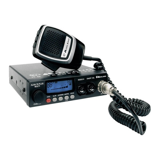
FUNCTION AND LOCATION OF THE CONTROLS RX/TX:TX=transmit mode; RX=receive mode SCAN mode EMG mode Frequency band selected. LOW: displayed when the radio transmits in low power (this mode is possible with some frequency bands only – see the Frequency band chart). LOCK: microphone (UP/DOWN buttons) lock enabled. - Page 4 MICROPHONE REAR PANEL ANTENNA S. METER ”EXT” jack: external loudspeaker jack.(the internal loudspeaker is PTT: transmission button excluded) UP/DOWN buttons: manual channels selector. Power 12.6V DC: power supply cable LOCK button: it allows you to lock the UP/DOWN buttons. S.Meter jack: it allows an external “S. Meter” connection 6 pin microphone connector Antenna connector (SO239 connector type)
-
Page 5: Installation
INSTALLATION REPLACING FUSE Safety and convenience are the primary consideration for mounting any pie- If you replace the fuse for DC power Cord, use F 2A 250V type. The parameters and the symbol of the fuse are indicated in the following label. ce of mobile equipment. -
Page 6: Frequency Band Chart
FREQUENCY BAND CHART Digits displayed Country Italy 40 CH AM/FM 4Watt Italy 34 CH AM/FM 4Watt Germany 80 CH FM 4Watt / 12 CH AM 1Watt Germany 40 CH FM 4Watt / 12 CH AM 1Watt Germany 80 CH FM 4Watt / 40 CH AM 1Watt Germany 80 CH FM 4Watt / 40 CH AM 4Watt Europe 40 CH FM 4Watt / 40 CH AM 1Watt CEPT 40 CH FM 4Watt... -
Page 7: Technical Specifications
TECHNICAL SPECIFICATIONS GENERAL Channels ...............(see the frequency band chart) Frequency Range* ...............26.565-27.99125 MHz Duty cycle (% on 1 hour) ......... TX 5% - RX 5% - Stand-by 90% Frequency Control ......................PLL Operating Temperature Range ..............-10°/+55° C DC input voltage ..................12.6V DC ±10% Size ....................180 (L)x35 (H)x140 (P) mm Weight ........................
Need help?
Do you have a question about the Alan 78 Plus Multi B and is the answer not in the manual?
Questions and answers