
Related Manuals for ASROCK A770CROSSFIRE - V1.0


Summary of Contents for ASROCK A770CROSSFIRE - V1.0
-
Page 1: User Manual
A770CrossFire User Manual Version 1.0 Published June 2008 Copyright©2008 ASRock INC. All rights reserved. 1 1 1 1 1... - Page 2 (including damages for loss of profits, loss of business, loss of data, interruption of business and the like), even if ASRock has been advised of the possibility of such damages arising from any defect or error in the manual or product.
-
Page 3: Table Of Contents
2.12 Serial ATA (SATA) / Serial ATAII (SATAII) Hard Disks Installation ................. 36 2.13 Hot Plug and Hot Swap Functions for SATA / SATAII HDDs and eSATAII Devices ................ 37 2.14 SATA / SATAII HDD Hot Plug Feature and Operation Guide ..38 2.15 Driver Installation Guide ............ - Page 4 3 . 3 . 3 . 3 . 3 . BIOS S BIOS S BIOS S BIOS SETUP UTILITY ETUP UTILITY ETUP UTILITY ETUP UTILITY ..........................................45 BIOS S ETUP UTILITY ........... Introduction ................45 3.1.1 BIOS Menu Bar ............... 45 3.1.2 Navigation Keys .............
-
Page 5: Package Contents
ASRock’s commit- ment to quality and endurance. In this manual, chapter 1 and 2 contain introduction of the motherboard and step-by-step guide to the hardware installation. Chapter 3 and 4 contain the configuration guide to BIOS setup and information of the Support CD. -
Page 6: Specifications
Conductive Polymer Capacitors) - Support for Socket AM2+ / AM2 processors: AMD Phenom FX / Phenom / Athlon 64 FX / Athlon 64 X2 Dual-Core / Athlon X2 Dual-Core / Athlon 64 / Sempron processor - Supports CPU up to 140W... - Page 7 - 6 x Serial ATAII 3.0Gb/s connectors, support RAID (RAID 0, Connector RAID 1, RAID 0+1, RAID 10 and JBOD), NCQ, AHCI and “Hot Plug” functions (see CAUTION 7) - 1 x eSATAII 3.0Gb/s connector (shared with 1 SATAII connector) (see CAUTION 8)
- Page 8 Overclocking may affect your system stability, or even cause damage to the components and devices of your system. It should be done at your own risk and expense. We are not responsible for possible damage caused by overclocking.
- Page 9 15. This motherboard supports ASRock AM2 Boost overclocking technology. If you enable this function in the BIOS setup, the memory performance will improve up to 12.5%, but the effect still depends on the AM2 CPU you adopt. Enabling this function will overclock the chipset/CPU reference clock.
-
Page 10: Premium 2008 And Basic Logo
Premium 2008 and Basic Logo Premium 2008 and Basic Logo Premium 2008 and Basic Logo Premium 2008 and Basic Logo For system integrators and users who purchase this motherboard and plan to submit Windows Vista Premium 2008 and Basic logo, please follow ®... -
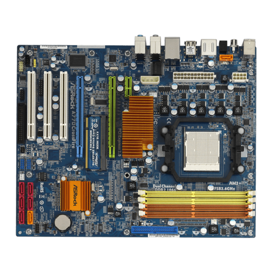
Page 11: Motherboard Layout
HDMI_SPDIF Header (HDMI_SPDIF1) Clear CMOS Jumper (CLRCMOS1) PCI Slots (PCI1- 3) Chassis Speaker Header (SPEAKER 1) PCI Express 2.0 x16 Slot (PCIE3; Blue) System Panel Header (PANEL1) SLI/XFire Switch Card Retention Slot Sixth SATAII Connector (SATAII_6) PCI Express 2.0 x16 Slot (PCIE2; Green) Fourth SATAII Connector (SATAII_4) PCI Express 2.0 x1 Slot (PCIE1/DE;... -
Page 12: Asrock Spdif I/O
Coaxial SPDIF Out Port ** 7 Front Speaker (Lime) PS/2 Keyboard Port (Purple) Microphone (Pink) * There are two LED next to the LAN port. Please refer to the table below for the LAN port LED indications. LAN Port LED Indications SPEED ACT/LINK... -
Page 13: Installation
Installation Installation Installation This is an ATX form factor (12.0-in x 9.6-in, 30.5 cm x 24.4 cm) motherboard. Before you install the motherboard, study the configuration of your chassis to en- sure that the motherboard fits into it. Pre-installation Precautions... -
Page 14: Cpu Installation
Step 4. When the CPU is in place, press it firmly on the socket while you push down the socket lever to secure the CPU. The lever clicks on the side tab to indicate that it is locked. -
Page 15: Installation Of Memory Modules (Dimm)
(the same brand, speed, size and chip-type) DDR2 DIMM pair in the slots of the same color. In other words, you have to install identical DDR2 DIMM pair in Dual Channel A (DDRII_1 and DDRII_2; Yellow slots;... - Page 16 DIMMs or the system components. Step 1. Unlock a DIMM slot by pressing the retaining clips outward. Step 2. Align a DIMM on the slot such that the notch on the DIMM matches the break on the slot. notch break...
-
Page 17: Expansion Slots (Pci And Pci Express Slots)
2.4 Expansion Slots (PCI and PCI Express Slots) 2.4 Expansion Slots (PCI and PCI Express Slots) There are 3 PCI slots and 3 PCI Express slots on this motherboard. PCI Slots: PCI slots are used to install expansion cards that have the 32-bit PCI interface. PCIE Slots: PCIE1/DE (PCIE x1 slot;... - Page 18 1. If you plan to install only one PCI Express VGA card on this motherboard, please install it on PCIE2 slot (Green). In this mode, you do not need to adjust the default setting of ASRock SLI/XFire Switch Card, and please do not remove or lose ASRock SLI/XFire Switch Card when it is still in working condition.
- Page 19 MSI RX1600PRO-TD256E Catalyst 7.3 Radeon X1300 PRO MSI RX1300PRO-TD256E Catalyst 7.3 1. If a customer incorrectly configures their system they will not see the performance benefits of CrossFire . All three CrossFire components, a CrossFire Ready graphics card, a CrossFire...
- Page 20 Take it out gently by holding its edges, and keep away from touching the connectors (Golden Fingers). Step 4. Reverse the card direction so as to have the “X8 / X8 MODE” wording side toward the retention slot base. Insert the card into the bottom of the base.
- Page 21 Step 5. Push the card down into the retention slot till both the retention arms firmly hold the card into position. Also, keep away from touching the connectors (Golden Fingers). Step 6. Install one Radeon graphics card to PCIE2 slot. For the proper installation procedures, please refer to section “Expansion Slots”.
-
Page 22: Ati Tm
Step 9. Connect the DVI monitor cable to the DVI connector on the Radeon graphics card on PCIE2 slot. (You may use the DVI to D-Sub adapter to convert the DVI connector to D-Sub interface, and then connect the D-Sub monitor cable to the DVI to D-Sub adapter.) -
Page 23: Surround Display Feature
Your computer will automatically reboot. After restarting your computer, please confirm whether the option “Enable CrossFire ” in “ATI Catalyst Control Center” is selected or not; if not, please select it again, and then you are able to enjoy the benefit of CrossFire feature. -
Page 24: Jumpers Setup
CLRCMOS1 for 5 seconds. However, please do not clear the CMOS right after you update the BIOS. If you need to clear the CMOS when you just finish updating the BIOS, you must boot up the system first, and then shut it down... -
Page 25: Onboard Headers And Connectors
(33-pin FLOPPY1) FLOPPY1 Pin1 (see p.11 No. 25) the red-striped side to Pin1 Note: Make sure the red-striped side of the cable is plugged into Pin1 side of the connector. Primary IDE connector (Blue) (39-pin IDE1, see p.11 No. 9) IDE1... - Page 26 SATAII function. The current eSATAII interface allows up to 3.0 Gb/s data transfer rate. Serial ATA (SATA) Either end of the SATA data cable Data Cable can be connected to the SATA / SATAII hard disk or the SATAII (Optional) connector on this motherboard.
- Page 27 If you don’t plan to use WiFi+AP functin on this motherboard, this header can be used as a 4-Pin USB 2.0 header to support one USB 2.0 port. To connect the 4-Pin USB device cable to this header, please refer to this picture for proper installation.
- Page 28 Though this motherboard provides 4-Pin CPU fan (Quiet Fan) support, the 3-Pin CPU fan still can work successfully even without the fan speed control function. If you plan to connect the 3-Pin CPU fan to the CPU fan connector on this motherboard, please connect it to Pin 1-3.
- Page 29 Though this motherboard provides 24-pin ATX power connector, it can still work if you adopt a traditional 20-pin ATX power supply. To use the 20-pin ATX power supply, please plug your power supply along with Pin 1 and Pin 13.
- Page 30 HDMI_SPDIF Cable Please connect the black end (A) of HDMI_SPDIF cable to the (Optional) HDMI_SPDIF header on the motherboard. Then connect the white end (B or C) of HDMI_SPDIF cable to the HDMI_SPDIF connector of HDMI VGA card. A. black end B.
-
Page 31: Hdmi_Spdif Header Connection Guide
HDMI (High-Definition Multi-media Interface) is an all-digital audio/video specification, which provides an interface between any compatible digital audio/video source, such as a set-top box, DVD player, A/V receiver and a compatible digital audio or video monitor, such as a digital television (DTV). A complete HDMI system requires a HDMI VGA card and a HDMI ready motherboard with a HDMI_SPDIF header. -
Page 32: Esataii Interface Introduction
SATAII hard disk. Currently, on the market, the data transfer rate of USB 2.0 is up to 480Mb/s, and for IEEE 1394 is up to 400Mb/ s. However, eSATAII provides the data transfer rate up to 3000Mb/s, which is much higher than USB 2.0 and IEEE 1394, and still keeps the convenience of Hot... - Page 33 How to install eSATAII? SATAII_6 eSATAII_TOP In order to enable the eSATAII port of the I/O shield, you need to connect the orange SATAII connector (SATAII_6; see p.11 No.14) and the eSATAII connector (eSATAII_TOP; see p.11 No.1) with a SATA data cable first.
- Page 34 Comparison between eSATAII and other devices IEEE 1394 400Mb/s USB 2.0 480Mb/s SATA 1.5Gb/s (1500Mb/s) eSATAII/SATAII 3.0Gb/s (3000Mb/s)
-
Page 35: Sataii Hard Disk Setup Guide
Before installing SATAII hard disk to your computer, please carefully read below SATAII hard disk setup guide. Some default setting of SATAII hard disks may not be at SATAII mode, which operate with the best performance. In order to enable SATAII function, please follow the below instruction with different vendors to correctly adjust your SATAII hard disk to SATAII mode in advance;... -
Page 36: Installation
STEP 4: Connect the other end of the SATA data cable to the SATA / SATAII hard disk. 1. If you plan to use RAID 0 or RAID 1 function, you need to install at least 2 SATA / SATAII hard disks. If you plan to use RAID 0+1 or RAID 10 function, you need to install 4 SATA / SATAII hard disks. -
Page 37: Esataii Devices
SATA / SATAII HDD. What is Hot Swap Function? If SATA / SATAII HDDs are built as RAID 1 then it is called “Hot Swap” for the action to insert and remove the SATA / SATAII HDDs while the system is still power-on and in working condition. -
Page 38: Sata / Sataii Hdd Hot Plug Feature And Operation Guide
SATA / SATAII driver is available on our support website: www.asrock.com 4. Make sure to use the SATA power cable & data cable, which are from our motherboard package. 5. Please follow below instructions step by step to reduce the risk of HDD crash... - Page 39 Please do follow below instruction sequence to process the Hot Unplug, improper procedure will cause the SATA / SATAII HDD damage and data loss. Step 1 Unplug SATA data cable from SATA / SATAII HDD side. Unplug SATA 15-pin power cable connector (Black) from SATA / SATAII HDD side. Step 2...
-
Page 40: Driver Installation Guide
® ® ® Vista 64-bit on a RAID disk composed of 2 or more SATA / SATAII HDDs with RAID functions, please follow below procedures according to the OS you install. 2.16.1 Installing Windows 2.16.1 Installing Windows 2.16.1 Installing Windows 2.16.1 Installing Windows... -
Page 41: Installing Windows ® Vista Tm / Vista Tm 64-Bit With Raid Functions
” page, please insert the ASRock Support CD into your optical drive, and click the “Load Driver” button on the left on the bottom to load the AMD RAID drivers. AMD RAID drivers are in the following path in our Support CD:... -
Page 42: Installing Windows Xp / Xp 64-Bit / Vista Tm / Vista Tm 64-Bit With Raid Functions
(create, convert, delete, or rebuild) RAID functions on SATA / SATAII HDDs, you still need to set up “SATA Operation Mode” to [RAID] in BIOS first. Then, please set the RAID configuration by using the Windows RAID installation guide in the following path in the Support CD: .. -
Page 43: Tm Tm
” page, please insert the ASRock Support CD into your optical drive, and click the “Load Driver” button on the left on the bottom to load the AMD AHCI drivers. AMD AHCI drivers are in the following path in our Support CD:... -
Page 44: Untied Overclocking Technology
Untied Overclocking function, please enter “Overclock Mode” option of BIOS setup to set the selection from [Auto] to [CPU, PCIE, Async.]. Therefore, CPU FSB is untied during overclocking, but PCI / PCIE buses are in the fixed mode so that FSB can operate under a more stable overclocking environment. -
Page 45: Etup Utility
This section explains how to use the BIOS SETUP UTILITY to configure your system. The SPI Memory on the motherboard stores the BIOS SETUP UTILITY. You may run the BIOS SETUP UTILITY when you start up the computer. Please press <F2> during the Power-On-Self-Test (POST) to enter the BIOS SETUP UTILITY, otherwise, POST will continue with its test routines. -
Page 46: Navigation Keys
To jump to the Exit Screen or exit the current screen <ESC> Main Screen Main Screen Main Screen Main Screen Main Screen When you enter the BIOS SETUP UTILITY, the Main screen will appear and display the system overview. BIOS SETUP UTILITY Advanced H/W Monitor Boot Security... -
Page 47: Advanced Screen
(C) Copyright 1985-2003, American Megatrends, Inc. AM2 Boost This option appears only when you adopt AM2 CPU. If you set this option to [Enabled], you will enable ASRock AM2 Boost function, which will improve the memory performance. The default value is [Disabled]. Please refer to cau- tion 15 on page 9 for details. - Page 48 It will display Processor Maximum Voltage for reference. Multiplier/Voltage Change This item is set to [Auto] by default. If it is set to [Manual], you may adjust the value of Processor Frequency and Processor Voltage. However, it is recom- mended to keep the default value for system stability.
- Page 49 (C) Copyright 1985-2003, American Megatrends, Inc. Processor Frequency This option appears only when you adopt AM2 CPU. This item will show when “Multiplier/Voltage Change” is set to [Manual]; otherwise, it will be hidden. The range of the value depends on the CPU you adopt on this motherboard. However, for system stability, it is not recommended to adjust the value of this item.
- Page 50 Memory Clock This item can be set by the code using [Auto]. You can set one of the standard values as listed: [200 MHz (DDR2 400)], [266 MHz (DDR2 533)], [333 MHz (DDR2 667)] and [400MHz (DDR2 800)]. If you adopt Phenom CPU,...
- Page 51 [3CLK]. The default value is [Auto]. TRWTTO This option appears only when you adopt AM2 CPU. Use this to adjust TRWTTD values. Configuration options: [Auto], [2CLK], [3CLK], [4CLK], [5CLK], [6CLK], [7CLK], [8CLK] and [9CLK]. The default value is [Auto].
-
Page 52: Chipset Configuration
This item will switch the PCI Bus scanning order while searching for video card. It allows you to select the type of Primary VGA in case of multiple video controllers. The default value of this feature is [PCI]. Configuration options: [PCI] and [PCI Express]. -
Page 53: Acpi Configuration
If [Power On] is selected, the AC/power resumes and the system starts to boot up when the power recovers. Ring-In Power On Use this item to enable or disable Ring-In signals to turn on the system from the power-soft-off mode. -
Page 54: Ide Configuration
PCI Devices Power On Use this item to enable or disable PCI devices to turn on the system from the power-soft-off mode. PS/2 Keyboard Power On Use this item to enable or disable PS/2 keyboard to turn on the system from the power-soft-off mode. - Page 55 [ARMD]: This is used for IDE ARMD (ATAPI Removable Media Device), such as MO. LBA/Large Mode Use this item to select the LBA/Large mode for a hard disk > 512 MB under DOS and Windows; for Netware and UNIX user, select [Disabled] to disable the LBA/Large mode.
-
Page 56: Pcipnp Configuration
Use this item to enable or disable the S.M.A.R.T. (Self-Monitoring, Analysis, and Reporting Technology) feature. Configuration options: [Disabled], [Auto], [Enabled]. 32Bit Data Transfer Use this item to enable 32-bit access to maximize the IDE hard disk data transfer rate. 3.3.5 3.3.5 3.3.5 PCIPnP Configuration... -
Page 57: Floppy Configuration
Use this item to enable or disable floppy drive controller. Serial Port Address Use this item to set the address for the onboard serial port or disable it. Configuration options: [Disabled], [3F8 / IRQ4], [2F8 / IRQ3], [3E8 / IRQ4], [2E8 / IRQ3]. -
Page 58: Usb Configuration
Use this item to enable or disable the USB 2.0 support. Legacy USB Support Use this option to select legacy support for USB devices. There are four configuration options: [Enabled], [Auto], [Disabled] and [BIOS Setup Only]. The default value is [BIOS Setup Only]. Please refer to below descriptions for the details of these four options: [Enabled] - Enables support for legacy USB. -
Page 59: Hardware Health Event Monitoring Screen
Hardware Health Event Monitoring Screen Hardware Health Event Monitoring Screen In this section, it allows you to monitor the status of the hardware on your system, including the parameters of the CPU temperature, motherboard temperature, CPU fan speed, chassis fan speed, and the critical voltage. -
Page 60: Boot Screen
Boot Screen Boot Screen Boot Screen Boot Screen Boot Screen In this section, it will display the available devices on your system for you to config- ure the boot settings and the boot priority. BIOS SETUP UTILITY Main Advanced H/W Monitor... -
Page 61: Security Screen
Boot From Onboard LAN Use this item to enable or disable the Boot From Onboard LAN feature. Boot Up Num-Lock If this item is set to [On], it will automatically activate the Numeric Lock function after boot-up. 3.6 Security Screen... -
Page 62: Exit Screen
BIOS SETUP UTILITY. Discard Changes and Exit When you select this option, it will pop-out the following message, “Dis- card changes and exit setup?” Select [OK] to exit the BIOS SETUP UTILITY without saving any changes. Discard Changes When you select this option, it will pop-out the following message, “Dis-... -
Page 63: Software Support Software Support
4.2.1 Running The Support CD 4.2.1 Running The Support CD To begin using the support CD, insert the CD into your CD-ROM drive. The CD automatically displays the Main Menu if “AUTORUN” is enabled in your computer. If the Main Menu did not appear automatically, locate and double click on the file “ASSETUP.EXE”...
Need help?
Do you have a question about the A770CROSSFIRE - V1.0 and is the answer not in the manual?
Questions and answers