Advertisement
Quick Links
About this Manual
This manual is included as a quick reference for installation. For
further information on the use of this device with an FACU, please
refer to the panel's manual.
Note: This manual should be left with the owner/operator of this
equipment.
This manual covers the following models:
SPPS-204-25R-WP Weather protected wall mounted speaker/
strobe 25V, red
SPPS-204-70R-WP Weather protected wall mounted speaker/
strobe 70V, red
SPP-204-25R-WP Weather protected wall/ceiling mounted
speaker 25V, red
SPP-204-70R-WP Weather protected wall/ceiling mounted
speaker 70V, red
Accessory: MP-300 End of line resistor 3.9 kΩ
Notes
• DO NOT PAINT OR ALTER FACTORY APPLIED FINISH IN
ANY WAY.
• Wiring must be in accordance with CSA C22.1 Section 32,
NFPA 70, and NFPA 72.
Description
The SPP-204 series weather protected speaker and SPPS-204
weather protected speaker/strobe provide a wide range of audible
and visual settings in a single compact device. The candela
settings on the speaker/strobe can be field-configured for 15, 30,
75, 110, 185, and 15/75 cd.
Dimensions
8 5/8" (219 mm) W
7 7/16" (189 mm) H
4 7/16" (112 mm) D
Specifications
Operating temperature:
Humidity range:
Strobe flash rate
Nominal strobe voltage:
Operating strobe voltage
range:
Nominal speaker voltage:
Speaker size
Terminal wire gauge
Installation environment:
*Note: For FWR signaling use a Mircom or Secutron panel.
1
SPPS-204-WP and SPP-204-WP Series
Weather Protected Speaker/Strobes
-40 °C to +66 °C
(-40 F to 151 F)
95% relative humidity at 60 °C
(140 F)
1 Hz (1 flash per sec.)*
Regulated 24 VDC / 24 VFWR
16-33 VDC/VFWR
25V or 70.7Vrms
4"
12-22 AWG
Outdoor environment wet location
Setting the Candela (SPPS-204 models)
The candela can be set to 15, 30, 75, 110, 185, 15/75.
Note: 185 cd setting is for General Signaling only.
The factory default setting is 15.
1.
Pull out the candela selector from the device.
2.
Re-insert the selector tab into the notch so that the desired
candela setting is in the middle and shows through the
window when the cover is in place.
(When removing or inserting the candela selector, ensure to
keep it straight).
Note: Select the candela setting before installing the device in the
mounting plate.
Figure 1:
Inserting candela selector
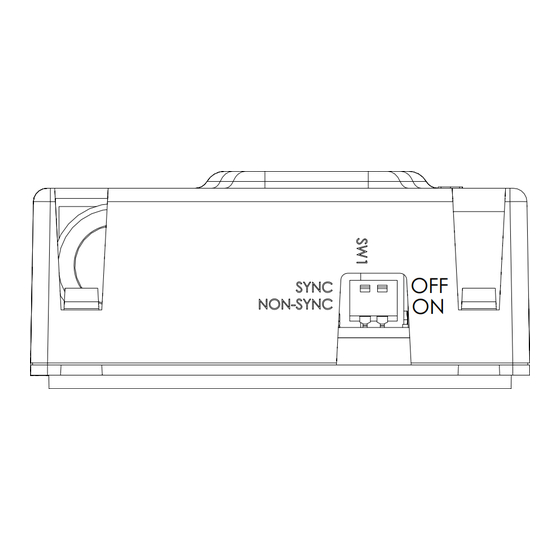
Setting the DIP Switches
Figure 2:
DIP switch
Input*
Regulated 24 VDC/FWR
(Non-synchronized)
Synchronized
*Note: Use "SYNC" when flash synchronization is required, either
through an external syncronization module or compatible FACU or
PSU supporting MGC sync protocol.
Use "NON-SYNC" when the appliances do not need to be
synchronized.
Note: DIP switch 1 default setting is OFF, synchronized.
Note: DIP switch 2 is not used. By default it is OFF.
www.mircomgroup.com LT-6512 Rev. 0 Jan. 2024
Selected candela
OFF
ON
DIP Switch 1
ON
OFF (default)
Advertisement

Related Manuals for MGC SPPS-204-WP Series


Summary of Contents for MGC SPPS-204-WP Series
- Page 1 Nominal speaker voltage: 25V or 70.7Vrms through an external syncronization module or compatible FACU or Speaker size 4” PSU supporting MGC sync protocol. Terminal wire gauge 12-22 AWG Use “NON-SYNC” when the appliances do not need to be synchronized. Installation environment: Outdoor environment wet location Note: DIP switch 1 default setting is OFF, synchronized.
- Page 2 Wiring FOR MODELS WITH STROBE FEATURE, STROBE INPUT POWER (NAC) SELECTABLE SPEAKER POWER (WATTS) Note: Connect speaker line between C Figure 3: Wiring taps Note: This device should be installed as per applicable local codes and standards and per the requirements of the authorities having jurisdiction.
- Page 3 Mount the unit to the wall or ceiling depending on the model. When mounting on the wall, mount the enclosure with the word TOP at the top, and mount the device with the MGC nameplate at 4 7/16” the bottom.
- Page 4 Note: The values in Table 4 are shown as percentages of the Angle OSPL (dBA) rated light output at any candela setting. +53° Warranty ±90° -5.3 Vertical Axis Purchase of all MGC products is governed by: https://www.mircom.com/product-warranty Angle OSPL (dBA) https://www.mircom.com/purchase-terms-and-conditions ±52° https://www.mircom.com/software-license-terms-and-conditions ±90° -5.3...
Need help?
Do you have a question about the SPPS-204-WP Series and is the answer not in the manual?
Questions and answers