Table of Contents
Advertisement
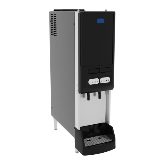
JDF- 2 NCV
(JDF- 2 S, VPDS)
INSTALLATION & OPERATING GUIDE
For Technical Service, contact Bunn-O-Matic Corporation at 1-800-286-6070.
Bunn-O-Matic Corporation
Post Office Box 3227, Springfield, Illinois 62708-3227
Phone (217) 529-6601 | Fax (217) 529-6644
www.bunn.com
57547.0001 C 03/24 © 2022 - 2024 Bunn-O-Matic Corporation
Advertisement
Table of Contents

Related Manuals for Bunn BUNN McDonald's JDF-2 NCV


Summary of Contents for Bunn BUNN McDonald's JDF-2 NCV
- Page 1 (JDF- 2 S, VPDS) INSTALLATION & OPERATING GUIDE For Technical Service, contact Bunn-O-Matic Corporation at 1-800-286-6070. Bunn-O-Matic Corporation Post Office Box 3227, Springfield, Illinois 62708-3227 Phone (217) 529-6601 | Fax (217) 529-6644 www.bunn.com 57547.0001 C 03/24 © 2022 - 2024 Bunn-O-Matic Corporation...
-
Page 2: Warranty
BUNN’S SOLE OPTION AS SPECIFIED HEREIN, TO REPAIR, REPLACEMENT OR REFUND. In no event shall BUNN be liable for any other damage or loss, including, but not limited to, lost profits, lost sales, loss of use of equipment, claims of Buyer’s customers, cost of capital, cost of down time, cost of substitute equipment,... -
Page 3: Table Of Contents
Carefully read and follow all notices on the equipment and in this manual. They were written for your protection. All notices are to be kept in good condition. Replace any unreadable or damaged labels. The model "JDF 2 NCV" is the internal customer name for the BUNN model, JDF-2S, VPDS. NOTE:... -
Page 4: North American Requirements
NORTH AMERICAN REQUIREMENTS • This appliance must be installed in locations where it can be overseen by trained personnel. • For proper operation, this appliance must be installed where the temperature is between 41°F to 90°F (5°C to 32°C). • For proper operation, this appliance must be installed where humidity is 50%. •... -
Page 5: Initial Setup
This dispenser must be connected to a chilled water supply line system with a 50 psi minimum dynamic operating pressure. This water source must be capable of producing a minimum flow rate of 8 fluid ounces (532 milliliters) per second. BUNN also requires a pressure gauge at the inlet of the dispenser for diagnostic purposes. -
Page 6: Plumbing Hookup
The plumbing connection is located on the rear of the dispenser. A 1/2” (12.7 mm) male flare adapter fitting is supplied, installed on the rear of the dispenser (Fig.1). NOTE: BUNN requires a pressure gauge at the inlet of the dispenser for diagnostic purposes. Accessory Part Number: 57524.1000 - Pressure Gauge Assy, 1/2" Inlet (Fig. 2) NOTE: Water pipe connections and fixtures directly connected to a potable water supply shall be sized, installed and maintained in accordance with federal, state and local codes. -
Page 7: Operating Controls
OPERATING CONTROLS Refrigeration Switch Remove lower splash panel. The refrigeration (compressor) switch is located on the Electrical Panel below the Circuit Board (Fig.5). This switch controls power to the relay contacts for the compressor and condenser fan motor. Lower Splash Panel FIG.5 Compressor Switch Program Switch Remove lower splash panel. - Page 8 OPERATING CONTROLS Product Dispense Switch (Portion Membrane Switch) Product Dispense Switch Membrane (Factory Setting: Sm-3 sec, Md Sm-6 sec, Md Lg-9 sec and Lg-12 sec.) Momentarily pressing and releasing one of the portion switches will initiate a timed dispense. Each station has four different timed dispenses which are preset at the factory.
-
Page 9: Product Setup
PRODUCT SETUP Two methods are available to operate the dispenser 3 sec. dispense flow test to verify water flow rate and sustainable dynamic 50psig water pressure. Option 2 is the easier method without having to remove the lower splash panel to access program switch. - Page 10 PRODUCT SETUP Loading (Concentrates) & Priming (continued) 5. Thoroughly mix the thawed concentrate in the bag by gently handling and maneuvering the bag around to mix concentrate before placing in dispenser cabinet. 6. Place the concentrate bag in the tray with the connection tube going through the large hole in the bottom of the tray.
- Page 11 PRODUCT SETUP Setting Ratio/Brix Using Refractometer 1. Load concentrate bag in dispenser. Dispense a few times to confirm the system has been primed and product is dispensing. 2. Disconnect or unplug dispenser. Remove the drip tray and splash panel to access control board, then replace drip tray.
-
Page 12: Ratio Target Chart
RATIO TARGET CHART Ratio Target Ratio Target 3 Sec. Water Dispense 3 Sec. Water Dispense 5 + 1 In Ounces 5 + 1 In Milliliters 8.11 9.73 240.0 288.0 8.28 9.94 245.0 294.0 8.45 10.14 250.0 300.0 8.62 10.34 255.0 306.0 8.79 10.55... -
Page 13: Cleaning & Preventive Maintenance
Weekly Cleaning Supplies: • KAY-5 Sanitizer/Cleaner Solution • 2 cleaning tubes provided with BUNN machine • KAY Peroxide Multi Surface Cleaner & Disinfectant Solution (3N1) • 2 empty small containers • Small-bristled brush • Clean, sanitizer-soaked towels... -
Page 14: Circuit Board Led Function List
CLEANING & PREVENTIVE MAINTENANCE Procedure - Weekly CIP (Clean In Place): NOTE: Clean and sanitize the interior juice lines. 1. Remove the juice concentrate bags and store in a separate refrigerator during cleaning. 2. Remove the drip tray and bag holders and take to the 3-compartment sink to wash, rinse and sanitize. Allow to air dry. 3. - Page 15 FUNCTION LIST Circuit Board LED Indicators LED # LED Color Illuminates: 1 Bath When bath temperature is above 34 degrees F. Flashes slowly when compressor is in a 6 minute delay period. Open bath thermistor circuit will flash #1 and #2 LED's 1 time every 3 seconds.
-
Page 16: Coolant Diagram
COOLANT SCHEMATIC DIAGRAM... -
Page 17: Schematic Wiring Diagram
*Jumper SHIELD SHIELD Wire GREY 120 VOLTS AC DISPENSE DISPENSE STATION STATION * Jumper Placement: J1-1 & J1-2 or J1-2 & J1-3 Dual Dispense capability disabled * Jumper Removed: Dual Dispense capability enabled 57543.0000 B 03/30/21 © 2020 BUNN-O-MATIC CORPORATION...
Need help?
Do you have a question about the BUNN McDonald's JDF-2 NCV and is the answer not in the manual?
Questions and answers
On off switch located