ASROCK 775TWINS-HDTV R2.0 User Manual
Hide thumbs
Also See for 775TWINS-HDTV R2.0:
- Manual to installation and configuration (22 pages) ,
- User manual (140 pages)
Table of Contents
Advertisement
Quick Links
Download this manual
See also:
User Manual
Advertisement
Table of Contents

Related Manuals for ASROCK 775TWINS-HDTV R2.0


Summary of Contents for ASROCK 775TWINS-HDTV R2.0
-
Page 1: User Manual
775Twins-HDTV User Manual Version 2.0 Published March 2006 Copyright©2006 ASRock INC. All rights reserved. 1 1 1 1 1... - Page 2 (including damages for loss of profits, loss of business, loss of data, interruption of business and the like), even if ASRock has been advised of the possibility of such damages arising from any defect or error in the manual or product.
-
Page 3: Table Of Contents
2.1 Screw Holes ..............12 2.2 Pre-installation Precautions ........... 12 2.3 CPU Installation .............. 13 2.4 Installation of Heatsink and CPU fan ......15 2.5 Installation of Memory Modules (DIMM) ......16 2.6 Expansion Slots ............. 17 2.7 Easy Multi Monitor Feature ..........18 2.8 Jumpers Setup .............. - Page 4 4.2 Support CD Information ..........45 4.2.1 Running Support CD ..........45 4.2.2 Drivers Menu ............45 4.2.3 Utilities Menu ............45 4.2.4 “LGA 775 CPU Installation Live Demo” Program .. 45 4.2.5 Contact Information ..........45 4 4 4 4 4...
-
Page 5: Introduction
ASRock’s consistently stringent quality control. It de- livers excellent performance with robust design conforming to ASRock’s commit- ment to quality and endurance. In this manual, chapter 1 and 2 contain introduction of the motherboard and step-by-step guide to the hardware installation. Chapter 3 and 4 contain the configuration guide to BIOS setup and information of the Support CD. -
Page 6: Specifications
Specifications Specifications Specifications Specifications Specifications - Micro ATX Form Factor: 9.6-in x 9.6-in, 24.4 cm x 24.4 cm Platform - LGA 775 for Intel Dual Core Pentium XE and Pentium ® ® ® Pentium 4 / Celeron D, supporting Conroe, Presler and ®... - Page 7 - 4 x Serial ATA 1.5Gb/s connectors Connector (Supports RAID 0, 1, 0+1, JBOD) (No support for “Hot Plug” function) - 2 x ATA133 IDE connector (supports 4 x IDE devices) - 1 x Floppy connector - 1 x Game header - 1 x IR header...
- Page 8 CPU. While CPU overheat is detected, the system will automatically shutdown. Before you resume the system, please check if the CPU fan on the motherboard functions properly and unplug the power cord, then plug it back again. To improve heat dissipation, remember to spray thermal grease between the CPU and the heatsink when you install the PC system.
-
Page 9: Vista Tm Basic Logo
Vista Basic logo, please adjust the shared memory size of ® onboard VGA to 64MB or less than 64MB. If you use onboard VGA with total system memory size above 512MB and plan to submit Windows Vista Basic logo, the ®... -
Page 10: Motherboard Layout
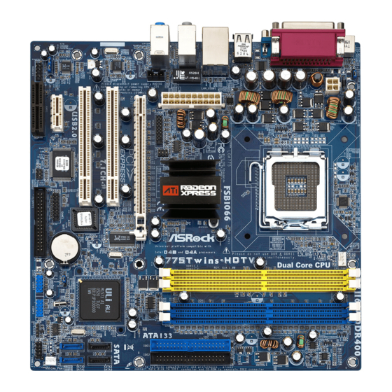
Chassis Speaker Header (SPEAKER 1) North Bridge Controller USB 2.0 Header (USB45, Blue) CPU Fan Connector (CPU_FAN1) USB 2.0 Header (USB67, Blue) 2 x 240-pin DDRII DIMM Slots Clear CMOS Jumper (CLRCMOS1) (DDRII_1, DDRII_2; Yellow) Floppy Connector (FLOPPY1) 2 x 184-pin DDR DIMM Slots Game Port Header (GAME1) (DDR1, DDR2;... -
Page 11: Hd 8Ch I/O
(No. 4) (No. 5) (No. 3) To enable Multi-Streaming function, you need to connect a front panel audio cable to the front panel audio header. After restarting your computer, you will find “Mixer” tool on your system. Please select “Mixer ToolBox”... -
Page 12: Installation
Chapter 2 Installation Chapter 2 Installation 775Twins-HDTV is a Micro ATX form factor (9.6" x 9.6", 24.4 x 24.4 cm) motherboard. Before you install the motherboard, study the configuration of your chassis to ensure that the motherboard fits into it. -
Page 13: Cpu Installation
Before you insert the 775-LAND CPU into the socket, please check if the CPU surface is unclean or if there is any bent pin on the socket. Do not force to insert the CPU into the socket if above situation is found. - Page 14 PnP cap to assist in removal. 1. It is recommended to use the cap tab to handle and avoid kicking off the PnP cap. 2. This cap must be placed if returning the motherboard for after service.
-
Page 15: Installation Of Heatsink And Cpu Fan
CPU and the heatsink to improve heat dissipation. Ensure that the CPU and the heatsink are securely fastened and in good contact with each other. Then connect the CPU fan to the CPU_FAN connector (CPU_FAN1, see page 10, No. -
Page 16: Installation Of Memory Modules (Dimm)
DIMMs or the system components. Step 1. Unlock a DIMM slot by pressing the retaining clips outward. Step 2. Align a DIMM on the slot such that the notch on the DIMM matches the break on the slot. notch break... -
Page 17: Expansion Slots
2.6 Expansion Slots (PCI, HDMR, and PCI Express Slots) There are 2 PCI slots, 1 HDMR slot and 2 PCI Express slots on this motherboard. PCI slots: PCI slots are used to install expansion cards that have the 32-bit PCI interface. -
Page 18: Easy Multi Monitor Feature
CLRCMOS1 for 5 seconds. However, please do not clear the CMOS right after you update the BIOS. If you need to clear the CMOS when you just finish updating the BIOS, you must boot up the system first, and then shut it down... -
Page 19: Onboard Headers And Connectors
(see p.9 No. 23) FLOPPY1 Pin1 the red-striped side to Pin1 Note: Make sure the red-striped side of the cable is plugged into Pin1 side of the connector. Primary IDE Connector (Blue) Secondary IDE Connector (Black) (39-pin IDE1, see p.9, No. 8) (39-pin IDE2, see p.9, No. - Page 20 (TV-OUT1: see p.9 No. 31) TV_Y header. USB 2.0 Header HD 8CH I/O accommo- USB_PWR dates 4 default USB 2.0 ports. If (9-pin USB67) those USB 2.0 ports on the I/O (see p.9 No. 21) DUMMY panel are not sufficient, this USB 2.0 header is available to...
- Page 21 HDA to function correctly. Please follow the instruction in our manual and chassis manual to install your system. 2. If you use AC’97 audio panel, please install it to the front panel audio header as below: A. Connect Mic_IN (MIC) to MIC2_L.
- Page 22 Please connect a CPU fan cable +12V to this connector and match CPU_FAN_SPEED (4-pin CPU_FAN1) FAN_SPEED_CONTROL the black wire to the ground pin. (see p.9 No. 5) ATX Power Connector Please connect an ATX power supply to this connector. (20-pin ATXPWR1) (see p.9 No.
-
Page 23: Installing Vga_Hdtv Panel To Enjoy Hdtv (High-Definition Tv) / Tv Support Function
J1 header Installing VGA_HDTV Panel Step 1. Either end of the VGA_2X8 cable can be connected to the J1 jumper of VGA_HDTV panel or the VGA1 header of this motherboard. Step 2. Either end of the AV/S_2X3 cable can be connected to the J2 jumper of VGA_HDTV panel or the TV-OUT header of this motherboard. -
Page 24: Hdtv (High-Definition Tv) Support Function
Internet. HDTV uses YPbPr connectors to receive input. The HDTV Component Video Adapter can be used in place of the standard AV Output cable to connect to an HDTV or other component video input devices, using component video cables. - Page 25 You are able to switch the monitor display to HDTV display by following the below instruction. Step 1. Connect one end of the VGA monitor cable to your monitor, and the other end to the VGA port (VGA1, see page 23, No. 4) of VGA_HDTV panel.
-
Page 26: Tv Support Function
When you install both VGA monitor cable and AV video cable to VGA_HDTV panel at the same time, the default enabled screen is the VGA monitor. You are able to switch the monitor display to TV display by following the below instruction. -
Page 27: Untied Overclocking Technology
Audio CODEC will not work. If you install Windows ® 2000 / XP OS without HDMR card inserted and plan to insert the HDMR card to this motherboard, you just have to restart your computer, then the Audio CODEC can... -
Page 28: Xp / Xp 64-Bit / Vista
RAID configuration on your system, or you may start to use “RAID Instal- lation Guide” to set RAID 0 / RAID 1 / RAID 0+1 / JBOD configuration before you install the OS. Before you start to configure the RAID function, you need to check the installation guide in the Support CD for proper configuration. -
Page 29: Bios Setup Utility
Power-On-Self-Test (POST) to enter the BIOS SETUP UTILITY, otherwise, POST will continue with its test routines. If you wish to enter the BIOS SETUP UTILITY after POST, restart the system by pressing <Ctl> + <Alt> + <Delete>, or by pressing the reset button on the system chassis. -
Page 30: Navigation Keys
To jump to the Exit Screen or exit the current screen <ESC> 3.2 Main Screen Main Screen Main Screen Main Screen Main Screen When you enter the BIOS SETUP UTILITY, the Main screen will appear and display the system overview BIOS SETUP UTILITY Advanced H/W Monitor Boot Security... -
Page 31: Advanced Screen
Use this to select Overclock Mode. The default value is [Auto]. Configura- tion options: [Auto], [CPU, PCIE, Sync.] and [CPU, PCIE, Async.]. If Overclock Mode is set to [Auto], you are not allowed to select PCI Frequency; if you select [CPU, PCIE, Sync.] or [CPU, PCIE, Async.], then PCI Frequency can be selected as [sync with CPU], [33.33 MHz], [33.80 MHz], [34.28 MHz], [34. - Page 32 If it shows “Locked”, then the item Ratio CMOS Set- ting will be hidden. If you use the ratio value to time the CPU frequency, it will be equal to the core speed of the installed processor.
-
Page 33: Chipset Configuration
[Auto], [Sync with CPU], [133MHz (DDR 266)], [166MHz (DDR 333)], [200MHz (DDR 400)]. If DDRII DIMM is inserted to DDRII slot, you may select [Auto], [Sync with CPU], [200MHz (DDRII 400)], [266MHz (DDRII 533)], [333MHz (DDRII 667)] as oper- ating frequency. - Page 34 Primary Graphics Adapter This item will switch the PCI Bus scanning order while searching for video card. It allows you to select the type of Primary VGA in case of multiple video controllers. The default value of this feature is [PCI]. Configuration options: [Onboard], [PCI] and [PCI Express].
-
Page 35: Acpi Configuration
[Auto], [Disabled], [30 C], [35 C], [40 C], [45 C], [50 C], [55 C], [60 C], [65 C], [70 C], [75 C]. If you select [Disabled], you will not find Thermal Throttling Duty Cycle option appear. The default value is [Auto]. -
Page 36: Ide Configuration
Use this item to enable or disable Ring-In signals to turn on the system from the power-soft-off mode. PCI Devices Power On Use this item to enable or disable PCI devices to turn on the system from the power-soft-off mode. PS/2 Keyboard Power On Use this item to enable or disable PS/2 keyboard to turn on the system from the power-soft-off mode. - Page 37 [AHCI], [RAID]. The default value is [AHCI]. IDE Device Configuration You may set the IDE configuration for the device that you specify. We will use the “Primary IDE Master” as the example in the following instruction, which can be applied to the configurations of “Primary IDE Slave”, “Sec- ondary IDE Master”, and “Secondary IDE Slave”...
-
Page 38: Pcipnp Configuration
[ARMD]: This is used for IDE ARMD (ATAPI Removable Media Device), such as MO. LBA/Large Mode Use this item to select the LBA/Large mode for a hard disk > 512 MB under DOS and Windows; for Netware and UNIX user, select [Disabled] to disable the LBA/Large mode. -
Page 39: Floppy Configuration
Use this item to enable or disable floppy drive controller. Serial Port Address Use this item to set the address for the onboard serial port or disable it. Configuration options: [Disabled], [3F8 / IRQ4], [2F8 / IRQ3], [3E8 / IRQ4], [2E8 / IRQ3]. - Page 40 Parallel Port Address Use this item to set the address for the onboard parallel port or disable it. Configuration options: [Disabled], [378], and [278]. Parallel Port Mode Use this item to set the operation mode of the parallel port. The default value is [ECP+EPP].
-
Page 41: Usb Configuration
Hardware Health Event Monitoring Screen Hardware Health Event Monitoring Screen In this section, it allows you to monitor the status of the hardware on your system, including the parameters of the CPU temperature, motherboard temperature, CPU fan speed, chassis fan speed, and the critical voltage. -
Page 42: Boot Screen
3.5 Boot Screen Boot Screen Boot Screen Boot Screen Boot Screen In this section, it will display the available devices on your system for you to config- ure the boot settings and the boot priority. BIOS SETUP UTILITY Main Advanced... -
Page 43: Security Screen
3.6 Security Screen Security Screen Security Screen Security Screen Security Screen In this section, you may set or change the supervisor/user password for the system. For the user password, you may also clear it. BIOS SETUP UTILITY Main Advanced H/W Monitor... -
Page 44: Exit Screen
BIOS SETUP UTILITY. Discard Changes and Exit When you select this option, it will pop-out the following message, “Dis- card changes and exit setup?” Select [OK] to exit the BIOS SETUP UTILITY without saving any changes. Discard Changes When you select this option, it will pop-out the following message, “Dis-... -
Page 45: Install Operating System
4 . 2 . 5 4 . 2 . 5 C o n t a c t I n f o r m a t i o n C o n t a c t I n f o r m a t i o n...
Need help?
Do you have a question about the 775TWINS-HDTV R2.0 and is the answer not in the manual?
Questions and answers