
Related Manuals for Dometic BAYSTAR FRONT MOUNT CYLINDER


Summary of Contents for Dometic BAYSTAR FRONT MOUNT CYLINDER
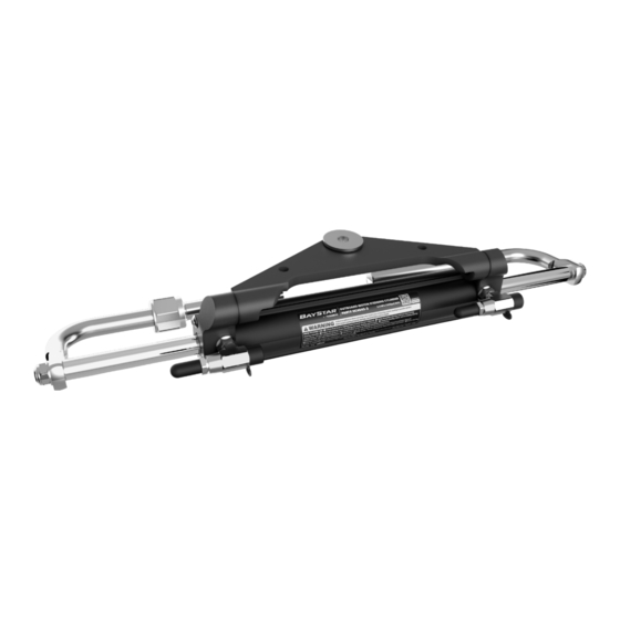
- Page 1 BAYSTAR FRONT MOUNT CYLINDER Hydraulic Steering for Outboard Powered Boats Rated to a Maximum of 150 HP (Total) Installation and User Manual — Book 22.3 [REVISION E] Form No. 998010 | © 2022 Dometic...
- Page 2 These safety alerts alone cannot eliminate all of the hazards that may be present while on the water. Dometic recommends that all users of the steering system take an accredited ‘boating safety course’, follow safe boating practices and are made aware of the environment that they will be in.
-
Page 3: Table Of Contents
INDEX Safety Information ..............ii Introduction ................1 Minimum Splashwell Dimensions ......... 2 Helm Mounting Template ............3 System Overview ..............5 Mounting the Helm ..............8 Re-Positionable ORB Hose Fitting Installation ......9 Hydraulic Hose/Tube Installation ........... 10 Cylinder Installation ............... 13 BayStar Compact Cylinders, HC4645-3, HC4647-3, HC4648-3, and HC4658-3 .......... -
Page 4: Safety Information
1. Install components as directed in all Installation Manuals Installation (including helm pumps, hoses and fitting kits). 2. DO NOT modify or substitute any component in any way without written consent from Dometic. CAUTION 3. Comply with all system ratings/regulations (boat/engine, U.S.C.G.). -4 helm pumps are fitted with - Cylinder MUST be compatible with engine(s) installed. - Page 5 WARNING The safety information provided below is intended to inform you of the dangers that may be present before, during and after the installation. It is critical that you read and understand ALL the points noted. 1. Check fluid level in highest helm pump (see page 26 for proper Prior to every use fluid level setting).
- Page 6 WARNING The safety information provided below is intended to inform you of the warning information on your products. Contact Dometic if labels are missing. Important Labels Figure 1...
-
Page 7: Introduction
Do Not use a wire coil type trim switch with a hydraulic steering system. Wire coil can wind tightly around the steering wheel shaft and prevent further steering! NOTICE For salt water applications Dometic recommends the use of a cylinder ground strap kit, part # HA5477. -
Page 8: Minimum Splashwell Dimensions
Before attempting installation, ensure that the splashwell of your boat has the following minimum dimensions. CYLINDER # OF MIN. ENGINE Minimum Splashwell MODEL NUMBER ENGINES CENTER DISTANCE Dimensions 21” (534 mm) 6” (153 mm) 5” (127 mm) HC4645/47H/ 48H/58H Twin engine applications not available at this time NOTES: Ensure there is no interference between the BayStar cylinder rod and the splashwell boot... -
Page 9: Helm Mounting Template
HELM MOUNTING TEMPLATE BayStar Helm (part# HH4311-4 and HH4314-4) Scale 1:1 HELM FLANGE OUTLINE (for reference only) Figure 3. 4-5/8" (118 mm) DIA. MAXIMUM COVERAGE, BAYSTAR HELM HH4314-4 & HH4311-4 NOTICE If you must photocopy this mounting template for use, check ALL measurements using a measuring device prior to using as a template. - Page 10 Note: This page left blank intentionally.
-
Page 11: System Overview
-3 fittings. Do NOT attempt to install an NPT pipe fitting into a helm hose fitting port. Doing so will lead to irreparable damage to the helm. ONLY use Dometic O-ring style hose fittings (ORB). Fluid Level and System Check STEP 3 •... - Page 12 NOTICE Specific installation may vary from the application depicted. Ensure the engine can be fully tilted into the splashwell and turned from port (engine stop) to starboard (engine stop) without interference occurring between the steering cylinder and engine cowling, engine hook and the splashwell or transom. WARNING Warranty will be void if BayStar system components are combined with any other manufacturer’s product.
- Page 13 Limited to boats rated to a MAXIMUM of 150 HP (Total). Twin engine Horse Power Limitations application not available. Engines using a 4.75" gearcase or large displacement engine de-tuned to 150 HP or less MUST use SeaStar steering. It is known that these engines generate higher steering loads that many will find unacceptable if using BayStar steering.
-
Page 14: Mounting The Helm
MOUNTING THE HELM Step 1: WARNING Determine desired mounting position. Ensure that the steering Use only self-locking fasteners wheel will not interfere with other functional equipment. Check for provided; substituting non-self adequate space behind the dash for fitting and line connections. locking fasteners can result in loosening or separation of equip- Step 2:... -
Page 15: Re-Positionable Orb Hose Fitting Installation
THREAD FITTING BY HAND UNTIL HERE WHILE TIGHTENING WASHER CONTACTS THIS FACE LOCKNUT (ITEM 1) Figure 7. Figure 8. WARNING Dometic recommends that the hose and hose fittings are checked on a regular basis to ensure the safe operation of the steering system. -
Page 16: Hydraulic Hose/Tube Installation
INSTALLATION Steering hoses/tubing and how they are installed are critical to the safe operation of your steering system. Dometic recommends the use of BayStar tubing or SeaStar hose ONLY. Use of any other tube/hose may drastically reduce system performance and safety. - Page 17 • Route steering hoses/tubing so that they have a gradual rise from the steering cylinder(s) to the helm pump. • If routing hoses/tubing through a blind area, ensure that the area is free and clear of any sharp edge, screw or any other object that may damage the hose.
- Page 18 BayStar hose to fitting installation STEP 3B • Remove protective caps. • Install hose end fitting onto intended fitting, tighten hand tight. • While holding the receiving fitting with a wrench, tighten hose fitting to 15 ft-lbs. WARNING When installed, confirm that the hoses are not being pulled or kinked over by pushing the engine(s) back and fourth.
-
Page 19: Cylinder Installation
CYLINDER INSTALLATION BayStar Compact Cylinders, HC4645-3, HC4647-3, HC4648-3, and HC4658-3 On the following pages of this instruction booklet you will find the assembly drawing for your specific application. In some cases, engine manufacturers will install plugs, caps WARNING and/or screws into the engine tiller arm. These plugs, caps and/ or screws MUST be removed prior to installation of the steering cylinder. - Page 20 Refer to page 29 for correct torque specifications of all installation hardware. WARNING ENGINE MANUFACTURER YEAR MODEL CYLINDER NOTE 1992 TO DATE 30–50 HP HONDA HC4645-3 4 Stroke Refer to figure 12a. Cylinder may not be centered when mounted due to short tiller tube. 1996 TO DATE 60–90 HP 4 Stroke...
- Page 21 Refer to page 29 for correct torque specifications of all installation hardware. WARNING ENGINE MANUFACTURER YEAR MODEL CYLINDER NOTE 1998 TO 2010 115–130 HP HONDA HC4647-3 4 Stroke WARNING In some cases, engine manufacturers will install plugs, caps and/or screws into the engine tiller arm. These plugs, caps and/or screws MUST be removed prior to installation of the steering cylinder.
- Page 22 Refer to page 29 for correct torque specifications of all installation hardware. WARNING ENGINE MANUFACTURER YEAR MODEL CYLINDER NOTE 1984 TO 1989 75–150 HP MERCURY/MARINER HC4645-3 2 Stroke Refer to figure 14a 1990 TO 2002 75–150 HP HC4645-3 2 Stroke Command Thrust must 1998 TO DATE 40–60 HP...
- Page 23 Refer to page 29 for correct torque specifications of all installation hardware. WARNING ENGINE MANUFACTURER YEAR MODEL CYLINDER NOTE 1977 TO 1990 65–150 HP HC4648-3 JOHNSON/EVINRUDE 2 Stroke Refer to figure 15d 1991 TO DATE 40–150 HP HC4645-3 2 Stroke Refer to figure 15a 1997 TO DATE 115 HP...
- Page 24 Refer to page 29 for correct torque specifications of all installation hardware. WARNING ENGINE MANUFACTURER YEAR MODEL CYLINDER NOTE 1986 TO 2003 40–50 HP YAMAHA 2 Stroke HC4645-3 Refer to figure 16a 1986 TO 2003 60 HP 2 Stroke HC4645-3 Refer to figure 16a.
- Page 25 Refer to page 29 for correct torque specifications of all installation hardware. WARNING ENGINE MANUFACTURER YEAR MODEL CYLINDER NOTE 1990 TO DATE 27–36 HP YANMAR Diesel HC4645-3 Requires Spacer Kit HO5090 (See page 21). WARNING In some cases, engine manufacturers will install plugs, caps and/or screws into the engine tiller arm.
- Page 26 Refer to page 29 or correct torque specifications of all installation hardware. WARNING ENGINE MANUFACTURER YEAR MODEL CYLINDER NOTE SUZUKI 1990 TO 2000 90–100 HP 2 Stroke HC4645-3 Refer to figure 18a 1998 TO DATE 40–70 HP 4 Stroke HC4645-3 Requires Spacer Kit HO5090 (See page 21) 2001 TO DATE 90–140 HP...
-
Page 27: Ho5090 Spacer Kit
HO5090 Spacer Kit For use with BayStar hydraulic steering cylinder HC4645-3, HC4647-3, HC4647-3, and HC4658-3. 1998 to DATE 40–140 HP JOHNSON/ Fig. 19. SUZUKI 4 Stroke 1998 to DATE 40 & 70 HP Fig. 20. EVINRUDE 4 Stroke 2001 to DATE 115–140 HP SUZUKI 4 Stroke Figure 19. -
Page 28: Reversing Compact Cylinder Engine Plate
REVERSING COMPACT CYLINDER ENGINE PLATE Recommended Tools 5/32” Allen head socket, with extension. 1. DO NOT attempt to reverse the pivot plate with the cylinder installed on the engine. (This may damage the steering shaft, causing irreparable damage.) 2. Remove the two cap screws from one end of the steering cylinder using the 5/32”... -
Page 29: Mounting To Outboard Engines Up To 60 Hp
MOUNTING TO OUTBOARD ENGINES UP TO 60 HP Small and mid sized outboard engines up to 60 HP may use a shorter tilt tube causing the BayStar Compact Steering Cylinder to be NOT centered with the engine in the straight ahead position. This will create reduced steering articulation in one direction. -
Page 30: Filling And Purging The System
Do not allow the fluid level to disappear into the helm pump, as this may introduce air into the system and increase your filling time. Due to recent upgrades in our steering system components, Dometic Hydraulic Fluid recommends use of SeaStar steering fluid ONLY in our hydraulic Requirements steering systems. - Page 31 Step 1 • Screw the threaded end of the filler tube into the helm filler port. FLUID BOTTLE • Remove the cap from the fluid bottle and holding upright screw into FILLER TUBE HELM the filler tube bottle cap. Poke hole in the bottom of the bottle. STEERING WHEEL •...
-
Page 32: Fluid Level And System Check
System Air Test • Place engine in the center position. • Manually push engine back and fourth. • While pushing engine back and fourth, watch the steering cylinder “body” move. If cylinder body moves more than 1/8”, this is a sign that there is still air remaining in the system and further bleeding is required. - Page 33 • If leaks are noticed they MUST be repaired prior to operating boat. After repair repeat bleeding procedures as outlined in this manual. • Repeat to the Port direction and inspect ALL connections, fittings, seals and hoses for leaks. • If leaks are noticed they MUST be repaired prior to operating boat. After repair repeat bleeding procedures as outlined in this manual.
-
Page 34: Routine Maintenance
3. Check for mechanical play or slop throughout steering system, correct as required. 4. Check for signs of corrosion. If corrosion is present contact your dealer or Dometic. After every 200 hours or 12 months (which ever comes first). 1. All points noted above. - Page 35 2. Remove tiller nut; clean threads, re-grease using a good quality marine grease, then reinstall. NOTE: Ensure proper torque specification is met when reinstalling. 3. Remove support rod from cylinder shaft, clean and re-grease using a good quality marine grease. NOTE: Ensure proper torque specification is met when reinstalling.
-
Page 36: Troubleshooting Guide
This valve is set to 1000psi. mechanic only. Most faults occur when installation instructions are not followed and Dometic offers the following as in most cases will show up immediately upon filling the system. Below a guide only and will not assume are the most common faults, their likely cause and possible solutions. - Page 37 FAULT CAUSE SOLUTION Dirt in inlet check of helm pump. Contact repair center, or replace helm pump. Helm unit in system is very bumpy DO NOT attempt to access WARNING and requires too many check valves, or dismantle the helm pump turns from hardover in any way, doing so may lead to loss to hardover.
-
Page 38: Replacement Parts
This can result in a purchase of counterfeit or underperforming parts, despite the seller’s claims. With genuine Dometic OEM parts you won’t have to study a myriad of aftermarket options. You can simply replace your original part with one provided by Dometic. This replacement will perform as effectively as the original part, you won’t have to worry about its fit or reliability. - Page 39 WARNING Any maintenance/repairs on BayStar steering components must be performed by a qualified marine mechanic. HA4640 HA4641 HA4642 HA4643 USE WITH CYLINDER USE WITH CYLINDER USE WITH CYLINDER USE WITH CYLINDER HC4645-3 HC4647-3 HC4648-3 HC4658-3 Figure 28. PIVOT PLATE END GLAND BARREL SHAFT CAP SCREW...
- Page 40 (PART # HC4645-3, HC4647-3, HC4648-3, HC4658-3) BAYSTAR CYLINDER (PART # HC4645H, HC4647H, HC4648H, HC4658H) WARNING Any maintenance/repairs on BayStar steering components must be performed by a qualified marine mechanic. NOTICE + HF4202 is for use with BayStar tubing marked – ‘H’ ONLY. * Included in seal kits HP4600 and HP4601.
-
Page 41: Limited Warranty
• has been used on an engine/boat combination where the engine horsepower exceeds the rating established by the boat manufacturer; • has been used with other or as specified in the Dometic’s Owners Manual for the purchased product/product(s) which, in Dometic’s opinion, are incompatible with the Dometic’s product. - Page 42 Dometic Tech Support Phone: 800-730-4082 Email: marinesupport@dometic.com NOTE: The above Limited Warranty supersedes all previous versions and is a reproduced extract from Dometic publication: L-4940. Form No. 340124 05/18 REV B. Effective 01/01/2024.
- Page 44 Mobile living made easy. DOMETIC VANCOUVER 3831 NO.6 ROAD RICHMOND, B.C. CANADA V6V 1P6 www.dometic.com © 2022 DOMETIC PRINTED IN CANADA 04/24 ISO 10592 Please scan FORM NO. 998010 REV. E this QR code and watch our latest Boating Safety video.
Need help?
Do you have a question about the BAYSTAR FRONT MOUNT CYLINDER and is the answer not in the manual?
Questions and answers