Table of Contents
Advertisement
MARINE
CONTROL UNITS
Passport I/O Legacy, Passport I/O Compact,
AH-Passport I/O Legacy, AH-Passport I/O Compact
Passport I/O Digital Controls
EN
Installation and Operation Manual . . . . . . . .2
WARNING
Cancer and Reproductive Harm
www.P65Warnings.ca.gov
L-5508 | Form No. 341205 20210420 | ©2021 Dometic Corporation
Advertisement
Table of Contents

Subscribe to Our Youtube Channel
Related Manuals for Dometic Passport I/O Legacy


Summary of Contents for Dometic Passport I/O Legacy
- Page 1 Passport I/O Legacy, Passport I/O Compact, AH-Passport I/O Legacy, AH-Passport I/O Compact Passport I/O Digital Controls Installation and Operation Manual ..2 WARNING Cancer and Reproductive Harm www.P65Warnings.ca.gov L-5508 | Form No. 341205 20210420 | ©2021 Dometic Corporation...
-
Page 2: Table Of Contents
8 Maintenance . . . . . . . . . . . . . . . . . . . . . . . . . . 23 date product information, please visit www.dometic.com. -
Page 3: Understand Signal Words
• Use for purposes other than those described in this – ANSI/NFPA70, National Electrical Code (NEC) manual – American Boat and Yacht Council (ABYC) Dometic reserves the right to change product appearance and product specifications. 1 .4 General Safety Messages WARNING: ELECTRICAL SHOCK, FIRE, AND/ OR EXPLOSION HAZARD . -
Page 4: General Information
Measurements may vary ±0.38 in. (10 mm). All Passport control models have similar features, installation procedures, and functionality. 3 .1 Tools and Materials Dometic recommends that the following tools and materials be used while installing the Passport controls: Recommended Tools Phillips-head Screwdriver... -
Page 5: Specifications
(64 mm x 48 mm) Models Toggles between the ON and Power OFF modes 4 .2 Cable Length Brand identification. No Dometic operational function Display Cable 15.0 ft (4.6 m) Standard Cycles through the different fan speeds Alternate Air Temperature Sensor 7.0 ft (2.1 m) Standard... -
Page 6: Available System Inputs
Specifications Passport I/O Digital Controls 4 .3 Available System Inputs 30 A @ 100–120 VAC For CW Only: Heater Output Input (using compressor relay) 20 A @ 208–240 VAC Ambient or Inside Air Temperature 1/4 HP @ 100–120 VAC Sensor Pump Output High Refrigerant Pressure 1/2 HP @ 208–240 VAC... -
Page 7: Wiring Diagrams
Passport I/O Digital Controls Wiring Diagrams 5 Wiring Diagrams WARNING: ELECTRIC SHOCK HAZARD . Turn power off before performing any electrical installation or maintenance activities. Failure to obey this warning could result in death or serious injury. Figure 3 and Figure 4 provide examples of the DX and CW wiring for the Passport controls. -
Page 8: Installation
Installation Passport I/O Digital Controls SMX DISPLAYS ONLY For Humidistat For Changeover Switch 0-10 VDC Display Jacks Optional DC Blower Inside Temperature Sensor Jack Required Water-In Temperature Sensor Optional Water-Out Temperature Sensor Optional Outside Air Temperature Sensor Ground Water Valve Fan Run Capacitor Electric Heat Strip... -
Page 9: Choosing A Display Panel Location
2. Apply the adhesive strips to the bulkhead. If the adhesive strips cannot be used directly on the bulkhead, an optional plastic bulkhead adapter is available for purchase. Contact Dometic Customer Service. 5 Legacy Cutout Dimensions/ Passport Control Dimensions 2.9 in. (74 mm) 3.9 in. -
Page 10: Operation
Operation Passport I/O Digital Controls 7 .1 .1 Normal Heating or Cooling Cycle In AUTOMATIC mode, heating and cooling are supplied as required to meet the cabin temperature set point. • The system starts a cooling cycle once the cabin temperature exceeds the temperature set point by 2 °F (1 °C) and starts a heating cycle once the cabin temperature falls below the temperature set point by... - Page 11 Passport I/O Digital Controls Operation To provide heat when the required water • When a cooling or heating cycle initiates after the temperature is not available, install the optional system has been OFF for less than 75 seconds electric heater, and program parameter P-19. (5 minutes for Passport control displays with firmware See “Programming the Passport Control”...
-
Page 12: Understanding The Service Utility Commands (Dx Systems Only)
Operation Passport I/O Digital Controls 7 .2 Understanding the Service The service history log keeps these faults: Utility Commands (DX Systems Only) • High Refrigerant Pressure (HPF) • Low Refrigerant Pressure (LPF) DX systems include service utility commands. This section explains the self-test program, the hours meter, •... - Page 13 Passport I/O Digital Controls Operation Available Modes and Options for Operation Indicator Description/Mode Function The COOL mode indicator illuminates when the COOL mode is selected or when the Passport control is in an AUTOMATIC mode cooling cycle. Only the cooling system Cool operates.
-
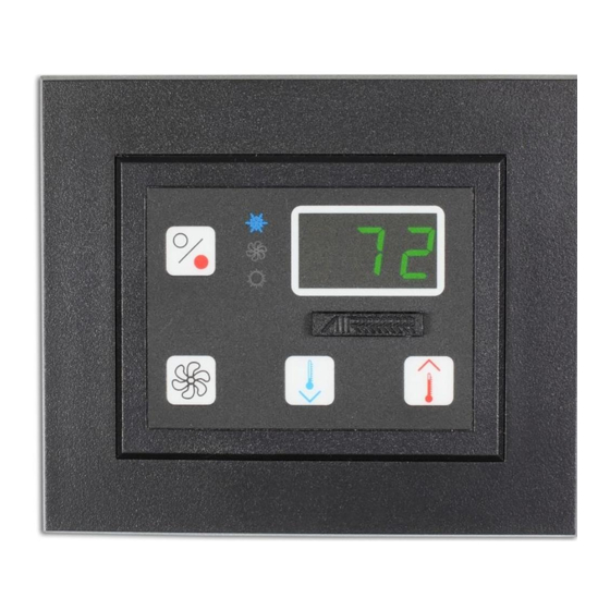
Page 14: Using The Passport Control Display Panel
Operation Passport I/O Digital Controls Indicator Description/Mode Function The Fan indicator illuminates when a manual fan speed is operating. Manual fan speeds allow the selection of a consistent desired fan speed. There are six manual fan speeds available (1=low and 6=high). The speed number is illuminated on the display when selected. - Page 15 Passport I/O Digital Controls Operation Combination Names Function Enter the DEHUMIDIFICATION mode: Power & Down Press the Power and Down buttons simultaneously while in the ON with display ON mode. Press the Power button to exit. & (Display ON) Display the service sensor temperature: Power &...
-
Page 16: Programming The Passport Control
Operation Passport I/O Digital Controls 7 .3 Programming the Passport Control Read the following important points before programming the Passport control: • If your air-conditioning unit has a Shaded-Pole (SP) fan motor instead of a Split-Capacitor (SC) High- Velocity (HV) fan motor, program SP into the fan motor type parameter before operating the Passport control. - Page 17 Passport control enters OFF mode after exit. 1. Enter Programming mode. See “Entering Programming Mode” on page 16. When contacting Dometic regarding the system or about programming the Passport control, note 2. Set the parameter value for parameter P-17 to “rSt.”...
- Page 18 Operation Passport I/O Digital Controls Parameter Name Factory Default Parameter Range 100–120 VAC: 75–105 208–240 VAC: 175–205 Low AC Voltage Set the built-in voltmeter circuit that monitors the AC input voltage prior to each cooling or Shutdown heating cycle. • For 100–120 VAC input power, set to OFF or 75–105 VAC. •...
- Page 19 Passport I/O Digital Controls Operation Parameter Name Factory Default Parameter Range nor = Normal Fan Operation rEF = Reversed Fan in HEAT Mode Reverse the automatic fan speeds during HEAT mode to improve heat output in cooler Reverse Automatic climates. P-13 Fan Speeds During •...
- Page 20 Setting • Parameter choices are between 10 (100 hours) and 250 (2500 hours). • Dometic recommends checking the air filter at least every 500 hours of operation. Available only in software version A21 and newer. Displays the elapsed time (in hours x10) since the timer was started or reset.
- Page 21 Passport I/O Digital Controls Operation Fault and Status Codes Fail Safe Levels Description DX Only Code Description DX CW Fail Safe Level 0: Provides minimal failsafe Indicates an air sensor failure. protection and is not recommended. • Only the ASF fault is detected and Indicates that the air filter replacement displayed.
-
Page 22: Navigation Tree
Operation Passport I/O Digital Controls 7 .4 Navigation Tree This section shows the menu flow for the Passport controls. FAN MODES DISPLAY INDICATORS OPERATING MODES Fan Mode Fan Modes Manual Fan Mode Cool Mode Up+Down Operating Modes Fan-Only Mode Heat Mode Fan+Power Service History Log Cycled/Continuous Fan Mode... -
Page 23: Maintenance
Passport I/O Digital Controls Maintenance 8 Maintenance 6. Verify that the fan is running and that a steady airflow is coming out of the supply-air grille. This section describes routine activities to maintain 7. Select a temperature set point lower than the current properly working system components. -
Page 24: Cleaning The Condenser Coil (Dx Systems Only)
Maintenance Passport I/O Digital Controls 8 .5 Cleaning the Condenser Coil Choose one of the methods below. The first two methods use a 50/50 nonpolluting, biodegradable (DX Systems Only) antifreeze/water solution: To avoid a marine-growth-fouled coil: 1. Pump the antifreeze solution into the overboard thru-hull fitting, and discharge the antifreeze solution 1. -
Page 25: Troubleshooting
Passport I/O Digital Controls Troubleshooting 9 Troubleshooting The following table describes some common occurrences that are not a result of defective workmanship or materials. Problem Possible Causes Recommended Solution The system does Turn on the air conditioning unit’s circuit breaker at the ship’s The air conditioning unit’s circuit breaker not power up. - Page 26 Troubleshooting Passport I/O Digital Controls Problem Possible Causes Recommended Solution The fan coil is See “There is a lack of airflow” in this table. The airflow is blocked or restricted iced. (continued) Set the fan speed to AUTOMATIC mode or increase the manual The fan runs too slow.
- Page 27 Passport I/O Digital Controls Troubleshooting Problem Possible Causes Recommended Solution The unit switches This is normal when the de-icing feature is enabled. Reprogram The de-icing feature is enabled due to to heat while in the de-icing cycle under the parameter settings. the coil possibly icing up during long run COOL mode.
- Page 28 Troubleshooting Passport I/O Digital Controls Problem Possible Causes Recommended Solution A high-pressure • Remove any obstructions in the return-air stream. The high-pressure switch is open (in fault is present. heating) due to improper airflow. • Clean the air filter and grille. (continued) •...
-
Page 29: Disposal
10 Disposal 11 Warranty Information Place the packaging material in the appropriate LIMITED WARRANTY AVAILABLE AT DOMETIC.COM/ recycling waste bins, whenever possible. Consult EN-US/TERMS-AND-CONDITIONS-CONSUMER/ a local recycling center or specialist dealer for WARRANTY. details about how to dispose of the product in... - Page 30 Passport I/O Digital Controls...
- Page 31 Passport I/O Digital Controls...
- Page 32 Mobile living made easy. dometic .com CONTACT US dometic .com/en-us/terms-and-conditions-consumer/contact-us A complete list of Dometic companies, which comprise the Dometic Group, can be found in the public filings of: DOMETIC GROUP AB Hemvärnsgatan 15 SE-17154 Solna Sweden...
Need help?
Do you have a question about the Passport I/O Legacy and is the answer not in the manual?
Questions and answers