Nespresso Gemini CS220 PRO Service Manual
Hide thumbs
Also See for Gemini CS220 PRO:
- User manual (28 pages) ,
- Manual (25 pages) ,
- Descaling manual (8 pages)

Related Manuals for Nespresso Gemini CS220 PRO


Summary of Contents for Nespresso Gemini CS220 PRO
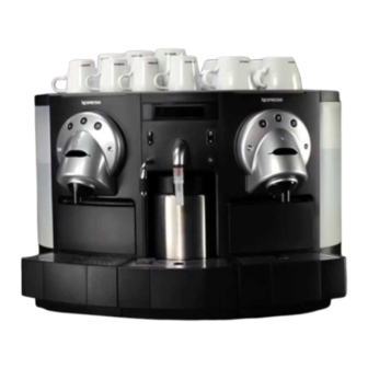
- Page 1 S E R V I C E M A N U A L C O F F E E M A C H I N E Gemini CS220 PRO EF 702 Gemini CS200 PRO EF 705 Version 1.1 en...
-
Page 2: Table Of Contents
C O N T E N T S 1 Main Components ....................6 1.1 Overview front side of Gemini CS220.............. 6 1.2 Overview front side of Gemini CS200.............. 7 1.3 Overview removable parts ................ 8 1.4 Overview rear side ................... 9 1.5 Overview operating elements and display ............. 10 1.6 Interior view...................... 11 1.7 Type plate ...................... 13 1.8 Fluid system ..................... 14 1.8.1 ... - Page 3 4.4 Descaling ...................... 45 4.4.1 Accessory ....................46 4.4.2 Safety instructions .................. 46 4.4.3 Preparation ..................... 47 4.4.4 Descaling and rinsing procedure for CS220 ........... 48 4.4.5 Descaling and rinsing procedure for CS200 ........... 54 4.5 Extraction unit maintenance ................ 59 4.5.1 Security check ..................59 4.5.2 Wearing parts ..................60 4.5.3 Lubrication of extraction unit..............61 5 Troubleshooting ....................
- Page 4 6.6.2 Removing hot water / steam module ............91 6.6.3 Replacing steam thermoblock of hot water / steam module ....92 6.6.4 Replacing pump of hot water / steam module......... 93 6.6.5 Replacing cappuccino keyboard of hot water / steam module....94 6.6.6 Replacing cappuccino module of hot water / steam module....95 6.6.7 Replacing solenoid valves of hot water / steam module ......96 6.6.8 Replacing steam outlet of hot water / steam module ......97 6.6.9 Replacing micro switch for milk container detection ....... 98 6.6.10Replacing micro switch for middle drip tray detection ......99 6.7 Hot water module (CS200 only) .............. 100 6.7.1 Removing display with logic module ............. 100 6.7.2 ...
- Page 5 P R E F A C E The purpose of this Service Manual is to provide the service personnel with all neces Please keep this sary information with regards to correct handling, maintenance and repair of the coffee manual together with the corresponding machines EF 702 and EF 705. service documentation. This way you are assured This Service Manual is based on the Gemini CS220 (EF 702) coffee machine mainly. to have the necessary information. Differences compared to the Gemini CS200 (EF 705) coffee machine are mentioned and illustrated if necessary. This manual should be used by the technicians as a valuable aid to guarantee the permanent readiness for use of the machines. In order to take full advantage of all the functions, it is absolutely necessary to follow the instructions in this manual. For fast access to information directly from the PC or MAC monitor, this manual is also ® available on CDROM. The required utility (Adobe Reader ), also on this CDROM, runs on PC and MAC computers. This service manual is available as PDFfile. The required utility software to read PDF ® files (Adobe Reader ) for PCs and MAC computers is included on the Gemini Service CDROM, can be downloaded (under http://www.adobe.com) for free please click the logo: 5 Service manual EF 702 / 705 ...
-
Page 6: 1 Main Components
M A I N C O M P O N E N T S 1 M A I N C O M P O N E N T S 1.1 Overview front side of Gemini CS220 1) Heating plate 9) Drip tray contacts (left, right) 2) Safety lid (left, right) 10) Drip tray support (left, right) 3) ... -
Page 7: Overview Front Side Of Gemini Cs200
M A I N C O M P O N E N T S 1.2 Overview front side of Gemini CS200 1) Heating plate 8) Drip tray contacts (left, right) 2) Safety lid (left, right) 9) Drip tray support (left, right) 3) Capsule slot (left, right) 10) Micro switches for capsule container detection 4) Coffee outlet (left, right) (left, right) 5) Cover for capsule ejection hole (left, right) 11) Support for middle drip tray 6) Water tank support (left, right) 12) Micro switch for drip tray detection 7) ... -
Page 8: Overview Removable Parts
M A I N C O M P O N E N T S 1.3 Overview removable parts 1) Milk container (thermos, 2 pcs.) 6) Capsule container (left, right) 2) Water filter (optional, left, right) 7) Drip grid (middle, CS220) 3) Water tank cover with lock (left, right), 8) Drip tray with thermos support (middle, CS220) necessary for direct water connection 9) Drip grid (left, right) 4) Water tank cover (left, right) 10) Drip tray with water level detection (left, right) 5) Water tank (left, right) with 11) Drip tray with water level detection (left, right, carrying handle (hinged) necessary for direct water connection) magnetic floater level control ... -
Page 9: Overview Rear Side
M A I N C O M P O N E N T S 1.4 Overview rear side 1) Back wall 5) Direct water connection 2) Service Stick connector (cover) 6) Mains switch 3) Safety instruction text 7) Mains connection 4) Type plate 8) Water tank connection valve (direct water ON/OFF) 9 Service manual EF 702 / 705 ... -
Page 10: Overview Operating Elements And Display
M A I N C O M P O N E N T S 1.5 Overview operating elements and display 1) Coffee button "small cup" (left, right, back lighted) 6) Passive display (LCD, back lighted) 2) Coffee button "medium cup" (left, right, back 7) Standby button (back lighted) lighted) 8) Portion button for hot milk (CS220, back lighted) 3) Coffee button "large cup" (left, right, back lighted) 9) Fill up button for hot milk (CS220, back lighted) 4) Portion button for hot water (back lighted) 10) Cup illumination (left, right, white / yellow) 5) Fill up button for hot water (back lighted) 11) Water tank illumination (left, right, white) 10 Service manual EF 702 / 705 ... -
Page 11: Interior View
M A I N C O M P O N E N T S 1.6 Interior view 1) Main module pcb 7) Flow meter 2) Thermoblock TB 2003 8) Pump CP4SP C2 3) Service Stick connector 9) Solenoid valve (direct water connection) 4) Solenoid valve (bistable) 10) Transformer 5) Valve lifter 11) Power module pcb 6) Water tank lighting 11 Service manual EF 702 / 705 ... - Page 12 M A I N C O M P O N E N T S 12) Logic module pcb 16) Solenoid valve (bistable) 13) Display module 17) Cappuccino module pcb (CS220) 14) Thermoblock TB 2003 18) Pump MPP1 15) Keyboard module Refer to "Exploded drawings" on page 146 to locate other components not visible in this illustration. 12 Service manual EF 702 / 705 ...
-
Page 13: Type Plate
M A I N C O M P O N E N T S 1.7 Type plate The type plate can be found at the backside of the coffee machine, carries the following information: 1) Brand name 2) Machine type 3) Rated voltage and power consumption 4) Origin 5) National approval seal 6) RoHS compliance sign (Restriction of the use of certain Hazardous Substances) 7) Bar code 8) Serial number 9) Nonwaste disposal symbol 10) Mark of conformity ... -
Page 14: Fluid System
M A I N C O M P O N E N T S 1.8 Fluid system Coffee preparation . Each coffee outlet has its own circuit. Both coffee outlets can work simultaneously Hot water preparation Both pumps (8) and thermoblocks (7) work simultaneously if there is no coffe prepara tion at the same time. Both water tanks (1 and 2) are emptied equally. Steam preparation (CS220) The steam outlet (18) has its own circuit which is supplied from the left water tank (1) only. 1.8.1 Fluid system of Gemini CS220 1) Water tank 1 10) Pump MPP1 2) Water tank 2 11) Bistable solenoid valve (reversed 3) Water tank connector assembled)* 4) Direct water connection 12) Bistable solenoid valve (5x) 5) ... -
Page 15: Fluid System Of Gemini Cs200
M A I N C O M P O N E N T S 1.8.2 Fluid system of Gemini CS200 1) Water tank 1 8) Pump CP4SP C2 (2x) 2) Water tank 2 9) Flow meter (2x) 3) Water tank connector 10) Bistable solenoid valve (4x) 4) Direct water connection 11) Counterpressure valve (2x) 5) Solenoid stop valve 2/2 way 12) Brewing chamber (2x) 6) Water tank connection valve 13) Drip tray, left (direct water ON/OFF) ... - Page 16 M A I N C O M P O N E N T S Consumption data CS220 D.C. Motors (2 pcs.) for extraction units Preheating time aprrox........... 67 s Voltage..............16 VDC Heating up ............24.5 Wh 1 medium coffee cup (40 ml*) .......4 Wh Bistable solenoid valves 2 medium coffee cups (2 x 40 ml* simultaneously) .6 Wh Voltage.............240 V / 50 Hz 1 large coffee cup (110 ml*) ........11 Wh Overpressure release approx. ......12 bar 2 large coffee cups (2 x 110 ml* simultaneously) ......20.5 Wh Hot water (125 ml*) .......... 8 Wh Capacities Foam milk (100ml*) ..........13.5 Wh 2 water tanks ............each 3 l ...
-
Page 17: 2 Operation
O P E R A T I O N 2 O P E R A T I O N 2.1 General information operational controls see For an overview of the "Overview operating elements and . display" on page 10 Preset filling amounts Coffee, portion and fill up buttons have preset filling amounts that can be modified (see "Programming the cup volume by pushbutton" on page 27). The operation of these buttons is time controlled: • Pressing a button for a maximum up to 1 sec releases the preset filling amount. • Pressing a button longer than 5 sec changes the presetting (depending on the power user menu setting). Multiple procurements The coffee machine can perfom two servings at the same time: An error message appears if three servings are ordered at the same time. 17 Service manual EF 702 / 705 ... -
Page 18: Preparation (For Test In After Sales Center)
O P E R A T I O N 2.2 Preparation (for test in After Sales Center) For a function control and some function tests (see "Function tests" on page 132) it is necessary to make the coffee machine ready for operation. 1. Check if cover is mounted on direct water connection and water tank connection For connection to the valve is turned off. water supply refer to "Direct water connec tion" on page 20. 2. Fill both water tanks with fresh water. A minimum water quantity is required to lift the magnetic float in the water tanks. Otherwise the display message "Fill water" will appear. 3. For testing the cappuccinatore unit (CS220) fill a milk container with enough cold milk, insert a straw with disposable foam device in milk container. 18 Service manual EF 702 / 705 ... - Page 19 O P E R A T I O N 4. Insert milk container with drip tray in machine (CS220). Check correct fit of all drip trays and capsule containers at the same time. 5. Connect coffee machine to mains (1, 2) and switch on mains switch (3). 6. Press standby button (4) and wait (50 70 sec.) till coffee machine is heated up and pushbutton illumination turns to white. An automatic rinsing of the coffee outlets is performed. Danger of burns! Hot steam and splashes of water. Be distant from steam outlet of CS220. 7. Press fill up button for approx. 20 sec to clean steam outlet (CS220). 8. Place disposable foam device on steam outlet afterwards (CS220). 19 Service manual EF 702 / 705 ...
-
Page 20: Direct Water Connection
O P E R A T I O N 2.2.1 Direct water connection The coffee machine is equipped with a direct water connection at the back wall to allow the automatic filling of the water tanks. For testing the direct water connection, the water supply has to meet the following requirements: Max. water pressure ....................10 bar Min. water pressure ....................0.8 bar Water temperature ..................max. 25 °C Water quality ............clean, potable water (use water filter) Minimal required installation material: Refer to separate manual "Installation guide for direct water connection" for additional installation material and special equipment for cof fee machine. 1) Stop valve on the water supply (symbolic illustration) 2) Noreturn valve (symbolic illustration), legal rule to avoid a water backflow into the water supply 3) Highpressure reinforced hose with suitable connections (G 3/4" for coffee machine) 20 Service manual EF 702 / 705 ... - Page 21 O P E R A T I O N 1. Fill both water tanks with fresh water. A minimum water quantity of 0.2 l in each water tank avoids air bubbles in the fluid system, splashing during initial operation. 2. Insert water tanks and check correct fit of all drip trays (left and right drip trays especially) and capsule containers at the same time. 3. Lock both water tank covers (special types) for safety reasons (3). 4. Connect noreturn valve to water supply. 5. Connect high pressure hose to water supply. 6. Remove cover and connect high pressure hose to solenoid valve. 7. Turn water tank connection valve to position ON. 21 Service manual EF 702 / 705 ...
- Page 22 O P E R A T I O N 8. Connect coffee machine to mains. 9. Switch on mains switch. 10. Press standby button: Depending on the water level in the tanks the message "Fill water" appears on the display. 11. Open stop valve of the water mains supply. Check tightness of the high pressure hose connections. An automatic rinsing of the coffee outlets is performed. 12. Wait (50 70 sec.) till coffee machine is heated up and pushbutton illumination turns to white. Then prepare hot water several times and check if water is replen ished in the water tanks. In case of problems refer to "Direct water connection problems" on page 71. Safety measures Operating errors • If no responsible person is present (e.g. at meal time, night etc.), the stop valve of can cause a flood the water mains supply must be closed. ing! • Adhere strictly to the following procedure for removal of water tanks: 1. Switch off standby button (1). 2. Turn water tank connection valve (2) to position OFF. 3. Unlock cover of water tank(s) (3). 4. ...
-
Page 23: Preparing Coffee
O P E R A T I O N If one or both water tanks are removed for a prolonged time, turn off stop valve of water supply as additional safety measure. 5. Reinsert water tank(s). 6. Lock cover of water tank(s) again. 7. Turn water tank connection valve to position ON. 2.3 Preparing coffee The procedure is identical for both coffee outlets: Coffee preparation can be aborted by pressing the same coffee button again (e.g. cup too small for preset filling amount). 2.4 Preparing hot water 1. Press portion button maximal 1 sec for a preset filling amount of hot water. 2. For additional hot water, press fill up button (+) as long as desired. 23 Service manual EF 702 / 705 ... -
Page 24: Preparing Cappuccino (Cs220)
O P E R A T I O N Hot water preparation can be aborted by pressing the portion button again (e.g. cup too small for preset filling amount). If there is no simultaneous coffee preparation, hot water is generated rapidly with the thermoblocks and pumps of both coffee units (refer to "Fluid system" on page 14). 2.5 Preparing cappuccino (CS220) The steam for the milk foam is gener ated with water from the left water tank only (refer to "Fluid system of Gemini CS220" on page 14). 1. Press portion button maximal 1 sec for a preset amount of milk foam. 2. For additional milk foam, press fill up button (+) as long as desired. Milk foam preparation can be aborted by pressing the portion button again (e.g. cup too small for preset filling amount). 3. Place cup under coffee outlet and prepare cappuccino. 24 Service manual EF 702 / 705 ... -
Page 25: Coffee Machine Displays
O P E R A T I O N 2.6 Coffee machine displays 2.6.1 Button colors White, blinking backlight ........... coffee machine is heating up A red backlight on these buttons locates White backlight.................. ready for operation the error and is Red backlight ..........error, user or service intervention necessary accompanied by an error display message. Button colors of coffee and cappuccino or hot water units can be different, depending on cause of error or operation mode. The standby mode of the coffee machine is indicated by a red backlighted standby button. During the shutdown procedure of the coffee machine (approx. 30 sec.), the standby button is blinking red. 2.6.2 Display messages The following display messages To change the user language of the dis are considerations for use, play messages, refer appear when a user intervention is necessary or in case of a malfunction. ... - Page 26 O P E R A T I O N Operation Display message Reason Remedy Water tank empty. Fill water tank. Fill water Floater in water tank stucked. Clean floater chamber in water tank. Water sensor defective. Replace water sensor. Drip tray missing or not inserted cor Reinsert drip tray. No drip tray rectly. Contact bank for level sensor defective. Align contacts or replace contact bank. Capsule container missing or not Reinsert capsule container. No capsule inserted correctly. container Micro switch(es) defective. Replace micro switch(es). Milk container or cover of milk container Insert milk container correctly. No milk container missing. Micro switch defective. Replace micro switch. Water in drip tray reaches contacts of Drip tray full ...
-
Page 27: 3 Programming
P R O G R A M M I N G 3 P R O G R A M M I N G 3.1 Programming the cup volume by pushbutton Cup volumes can be defined in the cus tomer settings of the This feature has to be enabled in the power user menu at first (program cup length ON, Service Stick software also see "Power user menu points" on page 30). (see "Customer settings (Client PC Software)" on page 38). Simply press and hold a coffee or portion button, until the desired filling amount is in the cup then release the pushbutton. A display message appears if the maximum value is reached. Set menu point "program cup lenght" to OFF afterwards to avoid changes by operating errors. 3.2 Power user menu This menu ... -
Page 28: Access To Power User Menu
P R O G R A M M I N G 3.2.1 Access to power user menu 1. Switch coffee machine to standby mode. 2. Press all coffee buttons of one coffee unit simultaneously, until the first menu point is displayed. Right and left coffee buttons correspond to the UP and DOWN ARROW keys on a key board. The middle coffee button corresponds to the ENTER key. 3. Use right and left coffee buttons to scroll up/down in the menu. 4. Use middle coffee button to to select a menu point, execute commands like "Exit" or "Descaling", edit and confirm the settings of menu points. Example: Change display language 1. Press middle coffee button to select language. The language is now marked with arrows. 2. Use left and/or right coffee button to choose a language. 3. ... -
Page 29: Power User Menu Selection
P R O G R A M M I N G 4. Use left and/or right coffee button to display EXIT command. 5. Press middle coffee button to confirm and terminate power user menu. 3.2.2 Power user menu selection Without filter(s): With installed filter(s): The primary water fil ter setting is part of the after sales menu (see page 31). * Only Gemini CS200 29 Service manual EF 702 / 705 ... -
Page 30: Power User Menu Points
P R O G R A M M I N G 3.2.3 Power user menu points Language Settings: English / German / French / Customer Factory setting: German Use this menu point to choose the display language. Beside the standard languages an additional customer specific language is available under the "Customer" setting. A customer specific language has to be uploaded to the coffee machine by Service Stick (see "Service Stick menu" on page 37). Program cup lenght Settings: OFF / ON Factory setting: OFF Use this menu point to inhibit or enable the programming of the cup volume by push button (see page 27). By pressing a coffee or portion button too long, a user can change preset filling amounts inadverently. Autooff Settings: OFF / 0.5h / 1h / ... / 10 h Factory setting: 4h Use this menu point to determine the rest period after that the coffee machine switches to standby. The "OFF" setting inhibits the standby mode. Cup Heater (only for Gemini CS200) Settings: OFF / ON Factory setting: OFF Use this menu point to switch on/off the cup heater. Coffee temperature Settings: Low / Optimal / High Factory setting: Optimal Use this menu point to change the optimal coffee temperature (86 °C) at the outlet if colder or hotter coffee is required. ... -
Page 31: After Sales Menu
P R O G R A M M I N G Direct water Settings: OFF / ON Factory setting: OFF Set this menu point to "OFF" if the water tanks are filled manually. "ON" only if the coffee machine is connected to the water supply. See "Direct water connection" on page 20 for more information. Filter: ON Commands: Change filter (left/right arrow) / Exit Use this menu point to replace a used water filter once the message "Change filter" appears on the display (see "Change filter elements (optional)" on page 42). This menu point has to be enabled in the after sales menu (see page 32). Exit Use this command to exit the power user menu and to resume standby mode. 3.3 After sales menu This menu is for service technicians only, allows basic settings and configurations, has two interdependent menu points ("Filter" and "Water hardness"), affects the power user menu structure. The customer setting file of the Service Stick software contains settings and configurations out of the after sales menu (see "Customer settings (Client PC Software)" on page 38). ... -
Page 32: After Sales Menu Selection
P R O G R A M M I N G 3.3.2 After sales menu selection Without filter(s): With installed filter(s): 3.3.3 After sales menu points The menu points "Filter" and "Descaling" are similar resp. identical to those in the power user menu. Filter: ON Commands and Settings ON activated: Change filter (left/right arrow) / Exit / OFF OFF activated: ON / Exit / OFF Factory setting: OFF Use this menu point to determine water filter installation: After sales menu Water filter(s) Remarks settings • Menu point "Water hardness" enabled No water filter(s) Filter : OFF • Menu point "Descaling" enabled in power user menu • Menu point "Filter" inhibited in power user menu • Menu point "Water hardness" inhibited Filter in water tanks Filter : ON ... - Page 33 P R O G R A M M I N G Water hardness Settings: 0 / 1 / 2 / 3 Factory setting: 2 Use this menu point to determine the descaling interval, depending on the water hard ness. This menu point appears only if "Filter" is set to OFF in the after sales menu. The available settings (0 3) correspond to a preset water volume, measured with the flow meters in the coffee machine, the water hardness. Water Fixed water volume Water reserve Water hardness Preparations hardness until descaling until machine is range (at 70 ml each) level message blocked 0 very soft / < 3.0° dH 1 ...
- Page 34 P R O G R A M M I N G 2. Add one drop of indicator liquid and mix. 3. Compare with Brita water hardness table. 4. Continue adding one drop at a time and mix until solution turns yellow. 34 Service manual EF 702 / 705 ...
- Page 35 P R O G R A M M I N G 5. Calculate the water hardness by comparing the number of drops used to the Brita water hardness water table. Use the following tabel to allocate the local water hardness to the correct water level setting: Carbonate hardness Water hardness level ºdH ºKH ºe ºf ppm (CaCO ) mMol/l 3 1 1.253 1,78 17.8 0,179 0 2 2.5 3,6 35.6 0,4 3 3.8 5,3 53.4 ...
- Page 36 P R O G R A M M I N G Descaling Use this command to start the descaling of the coffee machine. Refer to "Descaling" on page 45 for required accessories, preparations and descaling sequence. Direct water Settings: OFF / ON Factory setting: OFF Set this menu point to Danger of malfunc tion! "OFF" if the water tanks are filled manually. If menu point "Direct "ON" only if the coffee machine is connected to the water supply. water" is set to ON, water filters must not be placed See "Direct water connection" on page 20 for more information. in the water tanks. Only an external water filter is permitted. This menu point influences the water measurement of the coffee machine with installed water filter(s): • If "Direct water" is set to ON, the display message "Change filter" will occur when the total water flow of left and right flow meters reaches the setting (correct for external water filter). • If "Direct water" is set to OFF, the display message "Change filter" will occur if the left or right flow meter reaches the fixed value of 50 l (correct for filter cartridges in water tanks). ...
-
Page 37: Service Stick
P R O G R A M M I N G 3.4 Service Stick 3.4.1 Service Stick menu The Service Stick is an optional acces sory for initial opera tion, maintenance and aftersales service of the coffee machine. It is pro grammed with the Client PC Software. Depending on the software version, this menu example is subject to alterations. This menu appears on the display of the coffee machine after the Service Stick is connected to the interface connector on the back wall of the machine. Refer to the Service Stick user manual for instructions and menu explanation (delivered with Nespresso article no. 5716). 37 Service manual EF 702 / 705 ... -
Page 38: Customer Settings (Client Pc Software)
P R O G R A M M I N G 3.4.2 Customer settings (Client PC Software) Depending on the software version, this screenshot is subject to alterations. Screenshot from Client PC Software for Service Stick Customer settings are data files that contain the settings of the power user and after sales menu, can be generated and edited with the Client PC Software, can be downloaded to the coffee machine with the help of the Service Stick. The Client PC Software is delivered with the Service Stick and has to be installed on a PC. Predefined customer settings are an easy way to customize one or several coffee machines of the CS range. Refer to the Service Stick user manual for instructions and explanations of the respective settings. Check and adapt customer settings if the coffee machine is moved to a new site. 38 Service manual EF 702 / 705 ... -
Page 39: 4 Maintenance
M A I N T E N A N C E 4 M A I N T E N A N C E 4.1 Clean milk container This chapter contains basic maintenance work done by the cus Although the milk container is designed as thermos, the milk heats up slowly during tomer as well as special coffee machine operation and can spoil. Therefore a timer limits the residence time of maintenance instructions the milk container in the coffee machine. for the service technician. The insulation of the milk container is designed for an internal temperature rise of max. 10 °C in 8 hours based on a room temperature of 20 °C. If the predetermined residence time of 8 hours (resp. 1 hour for USA) is reached a display message appears, the cappuccinatore unit is blocked, ... -
Page 40: Reset A Locked Cappuccinatore Unit
M A I N T E N A N C E 5. Clean and refill milk container. 6. Store milk container in refrigerator. Use both supplied milk containers and circulate them. 7. Replace used milk container with second one out of refrigerator. 8. Insert a straw with disposable foam device in milk container. 9. Insert milk container with drip tray in coffee machine. The cappuccinatore unit resumes operation and the timer is resetted. 10. Attach disposable foam device to steam outlet. 4.1.1 Reset a locked cappuccinatore unit If no milk is used (milk container empty and clean): Pull out drip tray with milk container Health hazard ! from coffee machine and reinsert it after approx. 4 sec. Do not prolong the residence time of a filled milk container in the cof The timer, which limits the residence time of the milk container fee machine with this cannot be adjusted individually, method. cannot be deactivated. 40 ... -
Page 41: Daily Maintenance And Cleaning
M A I N T E N A N C E 4.2 Daily maintenance and cleaning Inform customer that daily cleaning and maintenance of the coffee machine is of utter importance, especially for the cappuccinatore unit. Danger of burns! Hot steam and splashes of water. Be distant from steam outlet. 1. Detach disposable foam device from steam outlet and swing it sideways. 2. Press fill up button for approx. 20 sec to clean steam nozzle. During standby operation drops of milk can be sucked up from the dispos able foam device into the steam nozzle by low pressure. This milk residues can curdle and clog the steam nozzle. Maintenance errors can cause a flood ing, if coffee machine is equipped with a direct water connection. Refer to "Safety measures" in "Direct water connec tion" on page 22 for instructions. 3. Switch coffee machine to standby. 4. Remove milk container and throw away disposable foam device with straw. 5. ... -
Page 42: Change Filter Elements (Optional)
M A I N T E N A N C E 8. Fill water tanks and reassemble coffee machine. 9. Check if water tank connection valve is set to OFF. Then switch on coffee machine. 4.3 Change filter elements (optional) Depending on the water supply of the coffee machine, different water filters are used. Water filters do not prevent descaling completely. Addi tional to the exchange of the filter cartridges it is rec ommended to descale the coffee machine once a year. 1) Claris water tank filters (with fix counter setting of 50 l ) Water tank filters 2) External water filter for direct water connection (e.g. Brita 06BC, Brita AquaQuell). must not be used in combination with a direct Individual counter setting: 200 5000 l for filtered water volume water connection. For water tank filters The coffee machine displays a message, if a filter cartridge in a water tank or an external only: As the water water filter has to be replaced. consumption is differ ent between the two water ... -
Page 43: Filter Cartridge Exchange Time
M A I N T E N A N C E 4.3.1 Filter cartridge exchange time The filter cartridge exchange time is determined by the water quantity passing through the water filter. This water quantity is measured with the flow meters of the coffee machine. Water tank filters The water quantity for each water tank filter is set to 50 l permanently. The display message "Change filter" will occur if the left OR right water flow meter reaches the setting. External water filter With a direct water connection and an external water filter, it is possible to set the filtered water volume up to 5000 l with the help of the Service Stick. Refer to "Service Stick menu" on page 37 to localize the menu point "Filter volume setting" or consult the Service Stick user manual. The display message "Change filter" will occur when the total flow of left AND right water flow meter reaches the setting. 4.3.2 Filter cartridge exchange procedure This section describes the exchange of filter cartridges in the water tanks only. For the external water filter refer to the supplier documentation. 1. Check display which filter cartridge has to be exchanged (see arrow). Left and right water tank have a different water consumption, dependent on the usage of the cappuccinatore unit. 2. Empty water tank. Remove and dispose used filter cartridge. 3. Insert a new filter cartridge in the water tank. Fill water tank with fresh water and insert it in the coffee machine. ... - Page 44 M A I N T E N A N C E Example with power user menu: Rinse left (right) water filter cartridge 5. Rinse the new filter cartridge for proper function with the command "Change filter". About 300 ml cold water flows out of the hot water outlet. The command "Change Filter" can be selected in the after sales menu also (see menu point "Filter" in "After sales menu points" on page 32. The water tank selection for rinsing is skipped, if the menu point "Direct water" is set to ON (external water filter). 44 Service manual EF 702 / 705 ...
-
Page 45: Descaling
M A I N T E N A N C E 4.4 Descaling When the message "Descaling needed" is displayed, the cof fee machine locks up after a given number of servings The coffee machine displays this message, if descaling is necessary. (protective measure). This message appears only, if the water filter setting is OFF in the after sales menu. A..............First display message "Descaling needed" B......Second display message "Descaling needed call service center" (coffee machine blocked) After the display message "Descaling needed" appears, a safety margin of 10 l water can be used until the coffee machine is blocked for safety reasons. Instruct the customer to call the service partner or to perform descaling himself immediately after the first display message "Descaling needed". The blockage of the coffee machine assures the correct maintenance of the fluid stystem. Under no circum The consequences of deblocking are: stances deblock a • Insufficient coffee quality coffee machine without descaling! • Longer preparation times ... -
Page 46: Accessory
2) A plastic pipe with threaded connec tion for steam outlet. 3) Special wrench for steam nozzle (CS220 only). This kit contains basic and reusable accessory for the descaling procedure. All 6 respectively 4 Stock number 5035/CS220 Stock number 5035/CS200 Stock number 5034 descaling packages are needed for one descaling process. This kit for the CS220 coffee This kit for the CS200 coffee Can with 5 litres of machine contains 6 descaling machine contains 4 Nespresso descaling packages and a descaling descaling packages and a agent for after sales manual. descaling manual. service. The following descaling description is based on this descaling manual but contains additional information. 4.4.2 Safety instructions After a premature termination of the descaling procedure, a rinsing is In case of emer executed (see display messages "Push a button"). Afterwards the descaling gency interrupt des caling procedure by procedure can only be restarted from the beginning. pressing the standby button or switch off cof fee machine with mains ... -
Page 47: Preparation
M A I N T E N A N C E Protective measures The decalcifier is aggressive to sur • Only use Nespresso decalcifier never use vinegar! faces and corrodes the • Wipe off decalcifier splashes with a wet cleaning rag immediatley. contacts on the left and right drip tray. • During cleaning of the drip trays, pay attention to the contact surfaces. 4.4.3 Preparation It is a good idea to perform the first descaling together with the responsible person for the coffee machine. Estimate a good quarter hour for the complete descaling process. 1. Switch coffee machine to standby. 2. Check if water tank connection valve at back wall is set to OFF. 3. Remove and empty all three drip trays. For locations with high room temperature: Store milk container in refriger ator during descaling procedure (CS220 only). 4. Throw away disposable foam device with straw (CS220 only). ... -
Page 48: Descaling And Rinsing Procedure For Cs220
M A I N T E N A N C E 5. Unscrew nozzle from steam outlet (CS220 only). Use special wrench (for CS220 only) supplied with descaling kit 5035/ GEMINI. 6. Reinsert drip trays. 7. Screw plastic pipe in steam outlet (CS220) resp. connect plastic pipe to hot water outlet (CS200). 8. Place both receptables under outlets of coffee machine. 4.4.4 Descaling and rinsing procedure for CS220 The command "Descaling" can be started out of the power user menu only if the water filter setting is OFF (in the after sales menu), can be started out of the after sales menu anytime, performs the complete descaling and rinsing procedure. A display message appears if user intervention is necessary. 48 Service manual EF 702 / 705 ... - Page 49 M A I N T E N A N C E Example with power user menu: 1. Start descaling procedure. The thermoblock which is responsible for steam production is cooled down. This step is skipped, if the thermoblock is cold already (e.g. after switchon of the coffee machine). 2. Remove and empty both water tanks. 3. Fill water tanks with indicated doses of descaling fluid and water. Use a measuring beaker to fill in water. 4. Insert water tanks in coffee machine. Do not exchange left with right water tank by mistake. 49 Service manual EF 702 / 705 ...
- Page 50 M A I N T E N A N C E 5. Continue descaling procedure by pressing a button. Refer to illustration for descaling steps and fluid course: • First the descaling fluid runs through the steam outlet into the receptable. • Next the descaling fluid runs through the associated drip tray valve into the left drip tray. • Next the descaling fluid runs through both hot water valves towards the hot water tube and into the receptable. • Next the descaling fluid runs through both drip tray valves of the coffee units into the left and right drip tray. • At the end the descaling fluid runs through both coffee outlets into the receptables until the water tanks are empty. 50 Service manual EF 702 / 705 ...
- Page 51 M A I N T E N A N C E 6. Empty all receptables and drip trays and reinsert them into coffee machine. 7. Empty water tanks and clean them thoroughly. 8. Fill water tanks with 3 l of fresh water each and insert them into coffee machine. The display message changes. 51 Service manual EF 702 / 705 ...
- Page 52 M A I N T E N A N C E 9. Start rinsing procedure by pressing a button. Refer to illustration for rinsing steps and water course: • First the water runs through the steam outlet into the receptable. • Next the water runs through the associated drip tray valve into the left drip tray. • Next the water runs through both hot water valves towards the hot water tube and into the receptable. • Next the water runs through both drip tray valves of the coffee units into the left and right drip tray. • At the end the water runs through both coffee outlets into the receptables until the water tanks are empty. 52 Service manual EF 702 / 705 ...
- Page 53 M A I N T E N A N C E 10. Empty and clean all receptables and drip trays. Dry drip tray contacts. 11. Detach plastic tube from steam outlet and mount steam nozzle. 12. Reinsert drip trays with milk container in coffee machine. 13. Attach disposable foam device to steam nozzle. 14. Refill water tanks if coffee machine has no direct water connection. 15. Press button to start normal operation. 16. Check position of water tank connection valve: Only if a direct water connection is existing, set valve to ON. End of the descaling and rinsing procedure for the CS220 coffee machine. 53 Service manual EF 702 / 705 ...
-
Page 54: Descaling And Rinsing Procedure For Cs200
M A I N T E N A N C E 4.4.5 Descaling and rinsing procedure for CS200 The command "Descaling" can be started out of the power user menu only if the water filter setting is OFF (in the after sales menu), can be started out of the after sales menu anytime, performs the complete descaling and rinsing procedure. A display message appears if user intervention is necessary. Example with power user menu: 1. Start descaling procedure. The thermoblock which is responsible for steam production is cooled down. This step is skipped, if the thermoblock is cold already (e.g. after switchon of the coffee machine). 2. Remove and empty both water tanks. 3. Fill water tanks with indicated doses of descaling fluid and water. Use a measuring beaker to fill in water. 4. Insert water tanks in coffee machine. Do not exchange left with right water tank by mistake. 54 Service manual EF 702 / 705 ... - Page 55 M A I N T E N A N C E 5. Continue descaling procedure by pressing a button. Refer to illustration for descaling steps and fluid course: • First the descaling fluid runs through both hot water valves towards the hot water outlet and into the receptable. • Next the descaling fluid runs through both drip tray valves of the coffee units into the left and right drip tray. • At the end the descaling fluid runs through both coffee outlets into the receptables until the water tanks are empty. 55 Service manual EF 702 / 705 ...
- Page 56 M A I N T E N A N C E 6. Empty all receptables and drip trays and reinsert them into coffee machine. 7. Empty water tanks and clean them thoroughly. 8. Fill water tanks with 3 l of fresh water each and insert them into coffee machine. The display message changes. 56 Service manual EF 702 / 705 ...
- Page 57 M A I N T E N A N C E 9. Start rinsing procedure by pressing a button. Refer to illustration for rinsing steps and water course: • First the water runs through both hot water valves towards the hot water outlet and into the receptable. • Next the water runs through both drip tray valves of the coffee units into the left and right drip tray. • At the end the water runs through both coffee outlets into the receptables until the water tanks are empty. 57 Service manual EF 702 / 705 ...
- Page 58 M A I N T E N A N C E 10. Empty and clean all receptables and drip trays. Dry drip tray contacts. 11. Detach plastic tube from hot water outlet. 12. Reinsert drip trays in coffee machine. 13. Refill water tanks if coffee machine has no direct water connection. 14. Press button to start normal operation. 15. Check position of water tank connection valve: Only if a direct water connection is existing, set valve to ON. End of the descaling and rinsing procedure for the CS200 coffee machine. 58 Service manual EF 702 / 705 ...
-
Page 59: Extraction Unit Maintenance
M A I N T E N A N C E 4.5 Extraction unit maintenance The extraction units are exposed to wear and tear during operation and contain wearing parts. Within the scope of a maintenance agreement it is advisable to exchange the wearing parts perodically. 4.5.1 Security check Malfunction of the safety lid (223) can cause injuries! Finger tips that are inserted in the capsule slot can be squeezed. Whenever a faceplate (116) is detached during maintenance, the correct function of the associated safety lid (223) must be tested after reassembly. Procedure 1. Insert an obstacle (e.g. srewdriver, pencil etc.) in the capsule slot. 2. Switch on mains switch and press standby button. 3. The coffee machine performs a selftest and closes/opens the extraction units. 4. As soon as the safety lid detects the obstacle, the concerning extraction unit stops and the display message "Machine blocked call service center" appears. 5. Remove the obstacle. If the obstacle is clamped in the extraction unit or damaged: • Check wiring of safety lid (223). ... -
Page 60: Wearing Parts
M A I N T E N A N C E 4.5.2 Wearing parts The special mounting tool (978) is neces sary to remove the shower, a part of the spare support plate (222). Replacement Pos. Designation mandatory optional 153 Outlet 702, extract unit, black X 195 Seal 758, extract head V2, black, 80 shore, 2x0.5mm, embossed X 199 Thrust ring 702, seal, black, extract unit X 221 Spare kit pyramid plate 702/705 X 222 Spare kit support plate 702/705 X 978 Mounting tool 702, alu (EFR no. 44269) — ... -
Page 61: Lubrication Of Extraction Unit
M A I N T E N A N C E 4.5.3 Lubrication of extraction unit Specified lubricant for extraction unit Use only specified Molykote PG65 Plastislip, art. no: 01945866 lubricant! Improper lubricants can decrease the service life of the extraction unit. nd Use this lubricant for vertical guiding ways and 2 generation motor spindles only. Vertical guiding ways Lubricating points on extraction unit Lubrication intervall Production date all generations Lubrication after every 10’000 coffee preparations Procedure 1. Remove extraction unit (refer to page 86). 2. Lubricate the vertical guiding ways with a litte grease. 3. Check smooth and quiet running of mechanism. 61 Service manual EF 702 / 705 ... - Page 62 M A I N T E N A N C E Motor spindle Due to further development, there exist 3 different spindle models: st nd rd Spindle 1 generation 2 generation 3 generation till end of Production date April 2007 under development March 2007 Appearance plastic spindle metallic spindle coated metallic spindle NO (see below) Lubrication NO (except if noisy) NO Replace a plastic spindle after 10’000 coffee preparations with kit "metallic spindle and grease", EF no. 0050973. nd Lubrication of 2 generation spindle (if noisy) ...
-
Page 63: 5 Troubleshooting
T R O U B L E S H O O T I N G 5 T R O U B L E S H O O T I N G This chapter gives useful hints and information for fault finding. It is not intended as a complete list of possible errors and malfunctions. 5.1 Check list With an acceptance check in accordance with this checklist, common errors are quickly found and corrected. Therefore, adhere to the sequence of the check list. Repair every occurring error and work the check list until it is completed. Procedures Checks / repair works • ... -
Page 64: Diagnostic With Service Stick
T R O U B L E S H O O T I N G 5.2 Diagnostic with Service Stick With the help of the Service Stick The Service Stick is an optional acces a quick and simple function test of the operating elements is possible, sory for initial opera statistic data can be retrieved and displayed. tion, maintenance and aftersales service of the Refer to the Service Stick user manual for detailed instructions and explana coffee machine. It is pro tions. grammed with the Client PC Software. 5.2.1 Function test menu Depending on the software version, this menu example is subject to alterations. 64 Service manual EF 702 / 705 ... -
Page 65: Statistic Data
T R O U B L E S H O O T I N G Use the function test menu to test the display, buttons (without standby button and mains switch), Ledlighting of buttons, coffee cups and water tanks. 5.2.2 Statistic data Statistic data are a summary of operational data like the count of various counters, which Statistic data can be are stored in the coffee machine. With the analysis of statistic data the maintenance rate compared with an odometer in a car. can be appointed and preventive maintenance can be carried out. They give information about the working life of the With the help of the Service Stick, statistic data can be coffee machine. displayed at the coffee machine line by line, stored and transferred to a computer. The coffee machine displays only a counter number and the linked value. For an explanation of these counter numbers see the following example or refer to the Service Stick user manual. Example of a CS220 statistic data file (excerpt) This statistic data file example is subject to ... -
Page 66: Error Messages
T R O U B L E S H O O T I N G 019; Counter_06: Total of Lungo cup right;9 020; Counter_07: Total of coffees without capsule left;6 021; Counter_08: Total of coffees without capsule right;9 022; Counter_09: Total of steam intakes;118 023; Counter_10: Total of hot water intakes;130 024; Counter_11: Total of all coffees left (servicecounter);62 025; Counter_12: Total of all coffees right (servicecounter);56 026; Counter_13: Total of steam time (min);21 027; Counter_14: Total of hot water volume (dl);166 028; Cleaning 029; Counter_15: Total of cold start rinsing left & right;3 030; Counter_16: Total of coffee water + rinse water left (dl);1 031; Counter_17: Total of coffee water + rinse water right (dl);1 etc. Important counters out of statistic data The values of the following counters are important for maintenance planning: Intake Counters Counter_11 Total of all coffees left (service counter) Counter_12 Total of all coffees right (service counter) Counter_13 Total of steam time (min), CS220 only Counter_14 Total of hot water volume (dl) 5.3 ... -
Page 67: Capsule Not Ejected Call Service Center
T R O U B L E S H O O T I N G 5.3.2 Capsule not ejected call service center This error message appears after coffee preparation, if no ejected capsule has been detected by the light barrier under the extraction unit. After 3 unsuccessful ejection attempts, the concerning coffee unit will be locked and its coffee buttons turn to red. Quick fix Instruct customer by phone to perform this quick fix. 1) Remove capsule container of locked coffee unit. 2) Reach into ejection hole and detach stucked capsule. There is no risk of getting hurt or burned. 3) Reset coffee machine: Switch standby button OFF and ON again to resume oper ation. Do not reset coffee machine without removing the stucked capsule first completely. If parts of a damaged capsule remain in the coffee extraction unit, this error can reappear. Additional measures (if safety lid is open) 1. Lit through capsule slot into brewing chamber with a pocket lamp. Check ejector mech 2. Insert teaspoon etc. through capsule slot and remove foreign object(s) completely anism of extraction ... -
Page 68: Machine Blocked Call Service Center
T R O U B L E S H O O T I N G 5.3.3 Machine blocked call service center For fault localization, check first which buttons of the coffee/capuccino units turn to red in combination with this error message. Possible reasons: • Defective NTC temperature sensor on thermoblock • NTC temperature sensor is not fixed • Thermoblock defective • Flow meter defective • Micro switch of safety lid defective • Motor of extraction unit blocked or defective Remedy: • Check the history bit counters in the statistic data file (refer to Service Stick manual). Every problem that leads to a ”machine blocked” message is tracked and monitored by history bits. For each history bit, two counters are in use: one which cannot be reset, and a resetable one. Example of history bit counters (excerpt) This excerpt of a sta tistic data file is sub ... -
Page 69: Drip Tray Display Messages
T R O U B L E S H O O T I N G 5.4 Drip tray display messages The left and right drip tray, as well as the middle drip tray of the CS200 coffee machine have contacts that are inserted in a contact bank for water level and attendance detec tion. These contact points can be the reason of irrational display messages concerning the drip trays. Erroneous display message and possible reasons No drip tray Consequence of corroded or defective contact(s): • Contacts can corrode if exposed to a descaling agent. • A deformed contact bank can be the reason for defective contacts. Drip tray full • Consequence of wet and shortout contacts by water drops (rarely reason, eg. after cleaning the drip trays). • An internal leak can affect the cable connectors of the contact bank wiring. Remedy: 1. Inspect contacts on drip tray: Dry, clean and polish contacts with a emery paper if necessary. 2. Inspect associated contact bank in coffee machine: Dry, clean and align contacts. Replace a corroded contact bank, refer to ... -
Page 70: Only Hot Water During Coffee Preparation
T R O U B L E S H O O T I N G 5.6 Only hot water during coffee preparation The used coffee capsule is not or only partly perforated on both sides. Possible reasons: • A second capsule is stucked in the brewing chamber of the extraction unit. • The capsule is not well positioned in the brewing chamber. • A deformed capsule border the hot water flows straight to the coffee outlet. Remedy: • Check for stucked capsule(s) in extraction unit. 5.7 No or too less steam for milk preparation Possible reasons: • The steam nozzle is clogged. Milk residues can curdle and clog the steam nozzle outlet. • The cappuccinatore unit is calcified. • An internal leak can reduce the rate of steam flow. Remedy: • Unscrew steam nozzle. Clean nozzle or replace steam nozzle. ... -
Page 71: Direct Water Connection Problems
T R O U B L E S H O O T I N G 5.9 Direct water connection problems Stick to the following procedure if the direct water connection does not work after instal lation. Check water supply installation • Machine correctly connected to the cold water supply? Rinse water supply • Water supply opened? pipe first, if it was not used for a long time! • Water pressure within limits (0.8 10 bar)? Dirty water can clog the • Noreturn valve mounted inversed? coffee machine. (See arrow head or similar sign on housing.) Check coffee machine setting • Water tank connection valve set to ON? • Menu point "Direct water" set to ON in after sales menu? Check if coffee machine is clogged The water circuit of the coffee machine is ... - Page 72 T R O U B L E S H O O T I N G 1) External water filter (example) 2) Filter insert in direct water solenoid valve 3) Mesh bottom in valve lifters (2x) For maintenance of an external water filter, refer to the supplier documenta tion. 72 Service manual EF 702 / 705 ...
-
Page 73: 6 Repairs
R E P A I R S 6 R E P A I R S These repair instructions This chapter con tains special safety help to localize components of the coffee machines with general drawings, and assembly notices. are based on exploded drawings combined with repair and mounting tips, Disregarding them may presuppose basic knowledge in repairing Nespresso coffee machines. lead to injuries and dam ages. As a rule, identical components (eg. pumps, thermoblocks etc.) are presented in detail only once. 6.1 Safety instructions Danger of electrocution! Mains voltage inside the coffee machine. Disconnect the mains plug before disassembly the coffee machine must be voltage free. Danger of burns! Hot parts and water under pressure inside the coffee machine (all ther moblocks in particular). Let coffee machine cool down before disassembly. ... -
Page 74: General
R E P A I R S If the obstacle is clamped in the extraction unit or damaged: • Check wiring of safety lid (223). • Replace a defect safety lid (refer to page 88). • Repeat security check. 6.2 General 6.2.1 Repair and mounting tips These general advices are completed with specific repair tips in this chapter. Additional information For components not mentioned in this repair chapter, refer to the exploded drawings in chapter "Exploded drawings" on page 146. Screw connections Do not overtighten screws. Plastic threads and inserts are delicate. Snap connections Parts of the case and components of the coffee machine are connected screwless with latches. When loosening these connections, proceed with care and patience to avoid causing any damage. Designation of spare parts The components in the following illustrations are indexed with position numbers. Added position numbers in brackets refer to similar, mirrorinverted parts not shown in the illus tration. See separate spare parts list for corresponding spare part numbers. Distinguish between spare parts of the CS220 and CS200 coffee machine. Electrostatic discharge protection When installing a new printed circuit board, the service technician must be earthed with a grounding band. Wiring arrangement Random changes in the wiring arrangement during a repair can cause ... -
Page 75: Tools And Accessories
R E P A I R S Protective measures • Do not change the course of internal wiring during repair. • Make sure that wires are distant form hot parts use existing cable clips. Residual water • If it is necessary to pull off hoses from components, hold ready a small beaker and a towel to collect and wipe away leaking water. • A special procedure is necessary to empty the fluid system of the coffee machine for repair or shipment: 1. Check if there is no display message "Drip tray full". Empty full drip trays if neces sary. 2. Switch machine to standby (standby button turns red after shutdown procedure). 3. Remove both water tanks. 4. Press and hold for 5 s: Portion and fill up buttons for hot water together with middle coffee button "medium cup" of right coffee unit. 6.2.2 Tools and accessories With the following assortment of tools, all repairs described can be made: • TORXscrewdriver set TX6, TX10, TX15, TX20, TX25, TX30 (can be substituted partly by torx bits of special mounting tool) • Slotted screwdriver no. 4 • Phillips (cross tip) screwdriver no. 0 • Flat wrench, span 14 mm, 10 mm AF ... -
Page 76: Overview Of Plugin Modules
R E P A I R S 6.2.3 Overview of plugin modules The coffee machine has a modular design for ease of servicing: Position Module Components Reference Pump 1 Coffee pump / flow meter modul Flow meter page 79 Contact bank Wearing parts 2 Extraction unit DC motor page 84 Spindle Keyboard Thermoblock 3 Hot water / steam module (CS220 only) Pump page 90 Cappuccino module pcb Micro switches Keyboard 4 Hot water module (CS200 only) page 100 Contact bank 76 Service manual EF 702 / 705 ... -
Page 77: General Disassembly
R E P A I R S 6.3 General disassembly This subchapter gives information how to open the casing of the coffee machine for a basic inspection and leakage check, the parts of the casing are mounted. 6.3.1 Opening the casing The following disas sembly steps are required for most of the repair work. 1. Remove power cord and all accessories first: water tanks, drip trays and capsule containers. 2. Unscrew cover from direct water connection and turn water tank connection valve to position ON (align lever with aperture in back wall). 3. Unscrew all 13 screws (6) and remove back wall (4). 77 Service manual EF 702 / 705 ... - Page 78 R E P A I R S 4. Use longnosed plier or a flat plier to pull out 4 locking levers (8, 9, 10, 11) under When laying down the heating plate (7). the water tank sup ports (66, 69), do not The locking levers are attached with elongated holes to the heating plate and tension the wiring of the have a limit stop. water tank lighting. 5. Lift heating plate (7) a little at the backside until all lateral pins are out of the posi tioning holes. Then lift remaining pins out of the positioning holes at the front side. 6. Detach ground wire at the underside of the heating plate (7). 7. To get access to lateral placed components of the coffee machine: Simply lift right and left water tank supports (66, 69) out of the anchoring. 78 Service manual EF 702 / 705 ...
-
Page 79: Coffee Pump / Flow Meter Module
R E P A I R S 6.4 Coffee pump / flow meter module 6.4.1 Removing coffee pump / flow meter module • Loosen screw (6) and pull out drawer (301 or 312) partially. • Disconnect resp. diasassemble all restricting cable and hose connections. The wiring of contact plate (111) is fixed with a cable clip at the underside of the extraction unit holder (103 or 101). Make sure to remove wiring from cable clip before pulling out drawer. 79 Service manual EF 702 / 705 ... -
Page 80: Replacing Coffee Pump
R E P A I R S 6.4.2 Replacing coffee pump The pump on the right coffee pump / flow meter module is illus trated as example. Pos. Designation 301 Drawer 702, right, black 312 Drawer 702, left, black 307 Pump holder 680, black, 64 sh, D13,5mm 308 Pump CP.04.117.0/ST/S/P, 230V 50Hz, light blue, professional, V2 309 Thermostat 115C/10,0A 1NT01L, connection 2xFZ6,3x0,8mm, straight 310 Clip thermostat, 1NT/01 311 Fluid connection elbow 702, neutral Repair tips • When installing a new pump the angled hose connection may have to be realigned. The white plastic Iid on the pump is rotatable and has two flat surfaces onto which the flat wrench can be placed. • To avoid possible flow fluctuations make sure not to kink hoses during reassembly. The white fluid connection elbow (311) is specially designed to avoid the clocking of the pump (less noise due to 0.6 mm hole diameter). Do not replace it with a standard fluid connection elbow (black case) used in other coffee machines. 80 ... -
Page 81: Replacing Thermostat Of Coffee Pump
R E P A I R S 6.4.3 Replacing thermostat of coffee pump The pump of the right coffee pump / flow meter module is shown as example. Pos. Designation 301 Drawer 702, right, black 308 Pump CP.04.117.0/ST/S/P, 230V 50Hz, light blue, professional, V2 309 Thermostat 115C/10,0A 1NT01L, connection 2xFZ6.3x0.8mm, straight 310 Clip thermostat, 1NT/01 312 Drawer 702, left, black 81 Service manual EF 702 / 705 ... -
Page 82: Replacing Flow Meter
R E P A I R S 6.4.4 Replacing flow meter The flow meter on the right coffee pump / flow meter module is illustrated as example. Pos. Designation 6 Screw KST/PT, 3.0x12, blue galvanized, round head, Torx10, CA point 301 Drawer 702, right, black 303 Flow meter FHKSC12R, 270 grade, V2, 4 lugs 304 Holding ring, D=3mm, type Starlock P6490 312 Drawer 702, left, black 313 Flow meter FHKSC12R, 90 grade, V2, 4 lugs Repair tip • Loosen screw (6) and pull out drawer (301, 312) partially to gain access to the flow meter (303, 313). Replace holding ring (304). 82 Service manual EF 702 / 705 ... -
Page 83: Replacing Left / Right Contact Bank
R E P A I R S 6.4.5 Replacing left / right contact bank The contact bank on the right coffee pump / flow meter module is illustrated as example. Pos. Designation 111 Spare contact plate 702/705, complete 301 Drawer 702, right, black 312 Drawer 702, left, black Repair tips • For access to the contact bank (111) remove coffee pump / flow meter module. • In case of corroded contacts check the other contact bank(s) also. 83 Service manual EF 702 / 705 ... -
Page 84: Extraction Unit
R E P A I R S 6.5 Extraction unit The left and right extraction units are identical and interchangeable, can be serviced and repaired the same way. 6.5.1 Replacing worn parts The wearing parts of the brewing chamber can be replaced onsite without removing the extraction unit. General repair tips • The jaw must be open and the safety lid (223) must be unscrewed to remove worn parts. How to open a closed jaw: 1. Switch machine to standby mode. 2. Enter power user menu (jaw of extraction unit opens automatically). 3. Exit power user menu. 4. Switch machine off with mains switch. The cup lighting (113) • Hold fast the cup lighting (113), when removing the faceplate (116) with cover (117) is inserted in a recess from the coffee outlet. at the underside of • When mounting the faceplate (116) again, make sure that the cup lighting (113) is the faceplate (116). inserted in the recess correctly. ... - Page 85 R E P A I R S Worn parts of lower brewing chamber (set no. 221) Repair tips (refer to preceeding illustration) • While loosen screw (152) press down and fix pyramid plate (156) with finger. • Lift ejector and lever up a stucked pyramid plate support (155) with a slotted screw driver if necessary. Then remove outlet (153). • Before mounting new parts exchange worn parts of upper brewing chamber first if needed, clean coffee outlet (153) or replace it if needed, clean brewing chamber. • When mounting the outlet (153) again, make sure that the centering pin is in the recess of the diecast part. Do not overtighten screw (152). Worn parts of upper brewing chamber (set no. 222) To get access to the upper brewing cham ber, all wearing parts of the lower brewing cham ber must be removed first. Repair tips • Unscrew shower (193) with special mounting tool (978, EF article no. 0044269) only. • Pay attention not to lose the thrust ring (199). • The sleeve (200) can be stucked and may be difficult to remove. Use an oring pick up tool or a dental pick to remove it. • All parts from set (222) must be mounted. 85 Service manual EF 702 / 705 ...
-
Page 86: Replacing Extraction Unit
R E P A I R S • When mounting new parts, check the correct fitting position of sleeve (200), thrust ring (199) and seal (195) see detail drawing. 6.5.2 Replacing extraction unit The right extraction unit is illustrated as example. 1. Remove hose (A) from fluid connector (462) at thermoblock. 2. Remove protective cover (504), (refer to "Replacing display, pcbs and transformer" on page 112). 3. Unplug connector (B) of d.c. motor (220) from main power module pcb. 4. Disconnect cable connection to micro switch of safety lid (223), see detail (D). 5. Remove cable connector (C) from holder (115), see detail (D). 6. Unscrew holder (115). Then press the two latches together and remove holder from casing. 7. Unscrew faceplate (116) with cover (117). 8. Hold fast the cup lighting (113), when removing faceplate (116) with cover (117) from coffee outlet. 9. Remove keyboard module (114) and let it hang down on its cable. 10. Hold and press down cup lighting (113) while pulling out the extraction unit (151). 86 Service manual EF 702 / 705 ... -
Page 87: Replacing Motor And Spindle Of Extraction Unit
R E P A I R S Repair tips • Pay attention to the 4 shock absorbers (185) on the extraction unit (151). They can fall off easily. • Hold and press down cup lighting (113) while inserting the extraction unit (151) back into the casing. • After reassembly of the extraction unit, make sure that there is a sufficient cable loop at the cable duct (104) to guarantee a checkless movement of the safety lid (203). • When mounting the faceplate (116) again, check if the cup lighting (113) is inserted in the recess correctly. • Perform a security check with the safety lid (223) after reassembly (refer to page 73). 6.5.3 Replacing motor and spindle of extraction unit Pos. Designation 213 Screw KST/PT 3.0x25 blue galvanized, round head, Torx10, CA point 220 Spare driver 702, extract unit, complete 224 Spare spindle 702/705, complete Repair tips • The jaw of the extraction unit must be closed to remove the motor (restricted access to motor fastening screws (213)). • For lubrication of the extraction unit refer to page 61. • Perform a security check with the safety lid (223) after reassembly (refer to page 73). 87 ... -
Page 88: Replacing Safety Lid With Micro Switch
R E P A I R S 6.5.4 Replacing safety lid with micro switch Pos. Designation 104 Cable duct 702, black 116 Faceplate 702 outlet, chrome plated 117 Cover 702, outlet, black 118 Screw M3x6, blue galvanized, flat head, Torx20 203 Screw M3x6, blue galvanized, flat head, Torx20 223 Spare safety lid 702 Repair tips • After exchange of the safety lid (223), make sure that there is a sufficient cable loop at the cable duct (104) to prevent any stress on the micro switch cable during the upanddown motion of the extraction unit. • Perform a security check with the safety lid (223) after reassembly (refer to page 73). The micro switch can only be replaced together with the complete safety lid. 88 Service manual EF 702 / 705 ... - Page 89 R E P A I R S • Pay attention to correct wiring of micro switch cable during reassembly. 89 Service manual EF 702 / 705 ...
-
Page 90: Hot Water / Steam Module (Cs220 Only)
R E P A I R S 6.6 Hot water / steam module (CS220 only) 6.6.1 Removing display with logic modul This step is neces sary for the removal of the hot water / steam module. 1. Remove display module (506) with logic module pcb (507): Press 2 lateral latches and lift unit out of guiding slots. 2. Lay down unit on coffee machine with display upward. Now it is possible to replace the cappuccino keyboard without removing the hot water / steam module at first (refer to page 94). 90 Service manual EF 702 / 705 ... -
Page 91: Removing Hot Water / Steam Module
R E P A I R S 6.6.2 Removing hot water / steam module Remove hot water / steam module to get access to following components: • Thermoblock (607) • Solenoid valve (571) • Pump (612) • Cappuccino module pcb (604) • Micro switch (603) 1. Unlatch cover (504) of pcb casing (4 latches). 2. Unscrew 2 fastening screws (6.1) of pcb casing. 3. Slide pcb casing up the holder (451) untill central fastening screw (6.2) is visible through hole (see detail drawing). 4. Unscrew central fastening screw (6.2) of the hot water / steam module. 5. ... -
Page 92: Replacing Steam Thermoblock Of Hot Water / Steam Module
R E P A I R S 6.6.3 Replacing steam thermoblock of hot water / steam module The steam ther moblock (607) is for the hot water / steam module (CS220) only. Do not exchange with a coffee thermoblock by mistake. The NTC tempera ture sensor (609) and the temperature fuses (615, 616) are for the steam thermoblock (607) only. Do not exchange with versions for coffee ther moblocks by mistake. Pos. Designation 410 Spring clip, D=1.3mm, V2, silicone hose 458 Clip TCO, TB2001, 0,5x10,0x21,0mm 460 Screw GF/Tapt. M4.0x 8, blue galvanized, round head, spring ring, Torx20 461 Screw GF/Tapt., M5,0x 8, geomet, round head/spring ring,Torx25, greased 605 Holder 702, thermoblock 2003, cappuccino 606 Nut M6, 6face, blue galvanized 607 Thermoblock 2003/N 230V/1080W, V2, nipples, tabs, M5thread 608 ... -
Page 93: Replacing Pump Of Hot Water / Steam Module
R E P A I R S 6.6.4 Replacing pump of hot water / steam module The pump of the hot water / steam module has no replaceable thermostat. Pos. Designation 601 Holder 702, black, cappuccino 611 Pressure spring, concentric, 1,6xD17,0/38,0mm, L=21,0mm, n= 4,5 (pump) 612 Pump 702, 230V/50Hz, thermostat fix mounted 613 Pump holder 702, black, 70 shore, cappuccino Repair tips • For access to the pump (612), refer to "Removing hot water / steam module" on page 91. • To avoid possible flow fluctuations, make sure not to twist hoses during reassembly. 93 Service manual EF 702 / 705 ... -
Page 94: Replacing Cappuccino Keyboard Of Hot Water / Steam Module
R E P A I R S 6.6.5 Replacing cappuccino keyboard of hot water / steam module Pos. Designation 570 Screw KST/PT, 3.0x10, blue galvanized, round head, Torx10 (WN 1452) 573 Keyboard module 702 (on/off, steam, hot water) 574 Holder 702, left, black 579 Support 702, hot water tube, black Repair tip • The cappuccino keyboard (573) can be replaced without pulling out the complete hot water / steam module. Remove display with logic module first (see page 90). 94 Service manual EF 702 / 705 ... -
Page 95: Replacing Cappuccino Module Of Hot Water / Steam Module
R E P A I R S 6.6.6 Replacing cappuccino module of hot water / steam module Pos. Designation 570 Screw KST/PT, 3.0x10, blue galvanized, round head, Torx10 (WN 1452) 601 Holder 702, black, cappuccino 604 Power PCB 702, 220230V, steam 605 Holder 702, thermoblock 2003, cappuccino Repair tip • For access to the cappuccino module (604), refer to "Removing hot water / steam module" on page 91. • Additional to the screwed connection, the protective case of the cappuccino module is attached with 4 latches to the holder (601). 95 Service manual EF 702 / 705 ... -
Page 96: Replacing Solenoid Valves Of Hot Water / Steam Module
R E P A I R S 6.6.7 Replacing solenoid valves of hot water / steam module These valves are fail safe, that is a closed valve opens if sub jected to an overpressure of approx. 12 bar. There fore the fitting position of the valves is crucial. Do not exchange with standard solenoid valves by mistake! Pos. Designation 410 Spring clip, D=1.3mm, V2, silicone hose 567 Plate 702, hood, cappuccino, black 570 Screw KST/PT, 3.0x10, blue galvanized, round head, Torx10 (WN 1452) 571 Magnetic valve, DEV122, 240V, type1586, 2side connection 601 Holder 702, black, cappuccino Repair tips • The solenoid valve at the steam outlet (555) can be replaced without pulling out the complete hot water / steam module. Refer to "Removing display with logic modul" on page 90. • The solenoid valve at the steam outlet (555) must not built in reversed. Check fitting position of valve before replacement. The other solenoid valve can be mounted only in the correct position. • For access to the lower solenoid valve, refer to "Removing hot water / steam ... -
Page 97: Replacing Steam Outlet Of Hot Water / Steam Module
R E P A I R S 6.6.8 Replacing steam outlet of hot water / steam module Outlet and cover of the CS200 steam out let are assembled identically. Pos. Designation 211 Screw KST/PT 3,0x10, blue galvanized, round head, Torx10 (EJOT PT) 554 Front panel 702, cappuccino, black, print: Nespresso Professional, silver 555 Outlet 702, cappuccino, black 556 Spare nozzle body 702, complete, cappuccino 560 Cover 702, cappuccino chrome Repair tips • To unscrew steam nozzle (556), use a flat wrench with 8 mm span. • To detach the grippedin cover (560), unscrew the steam outlet (555) first. Take care not to damage the cover. 97 Service manual EF 702 / 705 ... -
Page 98: Replacing Micro Switch For Milk Container Detection
R E P A I R S 6.6.9 Replacing micro switch for milk container detection Pos. Designation 567 Plate 702, hood, cappuccino, black 568 Micro switch D41RQGAC V2, 0.1A/250V, connection 4.8x0.8mm, 100k 569 Screw KST/PT, 3.0x16, blue galvanized, round head, Torx10, CA point Repair tip • For access to cappuccino module refer to "Removing hot water / steam module" on page 91. • For cam switch (562) replacing, see following illustration: 98 Service manual EF 702 / 705 ... -
Page 99: 10Replacing Micro Switch For Middle Drip Tray Detection
R E P A I R S 6.6.10 Replacing micro switch for middle drip tray detec tion Note that the CS200 middle drip tray is detected with a con tact bank instead. Pos. Designation 601 Holder 702, black, cappuccino 602 Holder 702, switch, cappuccino, black 603 Micro switch, XCG55V81LZ187, lever Repair tip • For access to the micro switch (603), refer to "Removing hot water / steam module" on page 91. 99 Service manual EF 702 / 705 ... -
Page 100: Hot Water Module (Cs200 Only)
R E P A I R S 6.7 Hot water module (CS200 only) 6.7.1 Removing display with logic module This step is neces sary for the removal of the hot water mod ule. 1. Remove display module (506) with logic module pcb (507): Press 2 lateral latches and lift unit out of guiding slots. 2. Lay down unit on coffee machine with display upward. 100 Service manual EF 702 / 705 ... -
Page 101: Removing Hot Water Module
R E P A I R S 6.7.2 Removing hot water module Remove hot water module to get access to following compo nents: • Hot water keyboard (573) • Hot water outlet (555, 560) • Contact bank (111) 1. Unlatch cover (504) of pcb casing (4 latches). 2. Unscrew 2 fastening screws (6.1) of pcb casing. 3. Slide pcb casing up the holder (451) untill central fastening screw (6.2) is visible through hole (see detail drawing). 4. Unscrew central fastening screw (6.2) of the hot water module. 5. Unscrew 2 screws (6.3) at the base (1). 6. Pull out hot water module at the front of the coffee machine. 7. ... -
Page 102: Replacing Hot Water Keyboard
R E P A I R S 6.7.3 Replacing hot water keyboard Pos. Designation 554 Front faceplate 705, water, black, print: Nespresso Professional, silver 573 Keyboard module 705, hot water 601 Holder 705, black Repair tip • For access to the hot water keyboard (573), refer to "Hot water module (CS200 only)" on page 100. 102 Service manual EF 702 / 705 ... -
Page 103: Replacing Hot Water Outlet
R E P A I R S 6.7.4 Replacing hot water outlet Pos. Designation 554 Front faceplate 705, water, black, print: Nespresso Professional, silver 555 Outlet 702, cappuccino, black 560 Cover 702, cappuccino chrome 573 Keyboard module 705, hot water 601 Holder 705, black Repair tip • To detach the grippedin cover (560), unscrew the steam outlet (555) first. Take care not to damage the cover. 103 Service manual EF 702 / 705 ... -
Page 104: Replacing Middle Contact Bank
R E P A I R S 6.7.5 Replacing middle contact bank Pos. Designation 111 Spare contact plate 702/705, complete 601 Holder 702, black, cappuccino Repair tip • In case of corroded contacts check the other contact banks also. 104 Service manual EF 702 / 705 ... -
Page 105: Basic Coffee Machine Nonmodular Parts
R E P A I R S 6.8 Basic coffee machine nonmodular parts In the general drawings the components to repair or to replace are shaded for easy recognicion. Similar components of the plugin modules are light shaded for reference. 6.8.1 Replacing coffee thermoblocks Position of components Pos. Designation 455 Thermoblock 2003/L 230V/1080W, welded nipples, connection FZ4,8x0,8 607 Thermoblock 2003/N 230V/1080W, V2, nipples, tabs, M5thread For replacing steam thermoblock (607), refer to page 92. 105 Service manual EF 702 / 705 ... - Page 106 R E P A I R S Coffee thermoblock component parts Pos. Designation 451 Holder 702, thermoblock 2003, zinc plated 452 Insulation holder 737, neutral, 40 shore 453 Cover 702, thermoblock, neutral 454 Cover 702, thermoblock, neutral 455 Thermoblock 2003/L 230V/1080W, welded nipples, connection FZ4,8x0,8 458 Clip TCO, TB2001, 0,5x10,0x21,0mm 459 Sensor 770 thermoblock, complete, L=170mm, m/JST plug & M5 ring lug 460 Screw GF/Tapt. M4.0x 8, blue galvanized, round head, spring ring, Torx20 461 Screw GF/Tapt., M5,0x 8, geomet, round head/spring ring,Torx25, greased 465 Spacer sleeve 737, blue zinc plated, Di=4,5/Da=6,0/L=52mm 466 Screw GF/Tapt., M4,0x60, blue galvanized, round head, Torx20, m/shaft, greased 467 Lock washer, D4,3x14,0x1,6, blue galvanized, M4 468 Insulation ring 737, silicone, 40 shore 469 Temperature fuse (152 °C) 470 Temperature fuse (152 °C) 106 ...
- Page 107 R E P A I R S Replacing NTC temperature sensor Pos. Designation 454 Cover 702, thermoblock, neutral 455 Thermoblock 2003/L 230V/1080W, welded nipples, connection FZ4.8x0.8 459 Sensor 770 thermoblock, complete, L=170mm, m/JST plug & M5 ring lug 461 Screw GF/Tapt., M5.0x8, Geomet, round head, spring ring, Torx25, greased Repair tip • Handle the delicate wires of the NTC sensor (459) with care. 107 Service manual EF 702 / 705 ...
- Page 108 R E P A I R S Replacing temperature fuses Pos. Designation 454 Cover 702, thermoblock, neutral 455 Thermoblock 2003/L 230V/1080W, welded nipples, connection FZ4.8x0.8 458 Clip TCO, TB2001, 0.5x10.0x21.0mm 460 Screw GF/Tapt. M4.0x 8, blue galvanized, round head, spring ring, Torx20 469 Temperature fuse (152 °C) 470 Temperature fuse (152 °C) Repair tip • When mounting a safety clip (458), make sure that the housing of the temperature fuse is positioned exactly below the safety clip. 108 Service manual EF 702 / 705 ...
-
Page 109: Replacing Solenoid Valves
R E P A I R S 6.8.2 Replacing solenoid valves Position of components Pos. Designation 316 Magnetic valve, 220240V, 2/2way, closed, type 1.007.126E300E 415 Magnetic valve DEV122 240V, 2side, FEP, connection long 571 Magnetic valve, DEV122, 240V, type1586, 2side connection For replacing solenoid valves (571), refer to page 96. 109 Service manual EF 702 / 705 ... - Page 110 R E P A I R S Replacing solenoid valves of coffee units Pos. Designation 102 Screw KST/PT, 3,5x12, blue galvanized, round head, Torx15 401 Valve holder 702, right, black 402 Valve holder 702, left, black 403 Fluid connection, Ishape, short, anthracite, 2xF 405 Clip, D=4mm, L=12mm, Inox 407 Fluid connection, Lshape, 90°, short, anthracite, 2xF 415 Magnetic valve DEV122 240V, 2side, FEP, connection long 463 Oring D3,40x1,90mm, 70 shore, red, 2components silicone 110 Service manual EF 702 / 705 ...
- Page 111 R E P A I R S Replacing solenoid valve of direct water connection Pos. Designation 102 Screw KST/PT, 3,5x12, blue galvanized, round head, Torx15 315 Holder 702, valve, 2way, black 316 Magnetic valve, 220240V, 2/2way, closed, type 1.007.126E300E 317 Elbow 702, silicone, transparent, water supply connection 111 Service manual EF 702 / 705 ...
-
Page 112: Replacing Display, Pcbs And Transformer
R E P A I R S 6.8.3 Replacing display, pcbs and transformer Position of components Try to download the customer settings onto the service stick before replacing a pcb. Pos. Designation Designation in wiring diagrams Spare control PCB 702 EU, 220230V, 504 Main module and power module VFlash parametrized 506 Display module 702, 2x20 symbols, lighting LCD 2 x 20 digits Spare control PCB 702, EU logic, 507 Logic module VFlash parametrized 604* Power PCB 702, 220230V, steam Cappuccino module * CS220 only See "Wiring diagrams" on page 124 for connector arrangement. For replacing power pcb 702 (604) refer to page 95. 112 Service manual EF 702 / 705 ... - Page 113 R E P A I R S Replacing display and logic module Pos. Designation 6 Screw KST/PT, 3,0x12, blue galvanized, round head, Torx10, CA point Gemini CS200 505 Cover 705, front panel, black, print: , silver Gemini CS220 505 Cover 702, front panel, black, print: , silver 506 Display module 702, 2x20 symbols, lighting 507 Spare control PCB 702, EU logic, VFlash parametrized 113 Service manual EF 702 / 705 ...
- Page 114 R E P A I R S Replacing main and power module Pos. Designation 6 Screw KST/PT, 3,0x12, blue galvanized, round head, Torx10, CA point 451 Holder 702, thermoblock 2003, zinc plated 504 Spare control PCB 702 EU, 220230V, VFlash parametrized 504 Spare control PCB 702 EU, V2, 220230V, VFlash parametrized, track fuse 1. Unlatch cover (504) of pcb casing (4 latches). 2. Disconnect wiring. 3. Unscrew 2 fastening screws (6) of pcb casing. 4. Slide pcb casing up the holder (451) and remove. 114 Service manual EF 702 / 705 ...
- Page 115 R E P A I R S Replacing transformer Pos. Designation 501 Holder 702, transformer, black 502 Transformer MS6122, 230V, EI78/40LPg, 5060Hz 503 Screw KST/PT 3,5x50, blue galvanized, round head, Torx10 (WN 1452) 504 Spare control PCB 702 EU, 220230V, VFlash parametrized 504 Spare control PCB 702 EU, V2, 220230V, VFlash parametrized, track fuse The transformer (502) has a builtin temperature fuse that cannot be replaced separatedly. 115 Service manual EF 702 / 705 ...
-
Page 116: Replacing Keyboards
R E P A I R S 6.8.4 Replacing keyboards Position of components Pos. Designation 114 Keyboard module 702, coffee, buttons lighting white CS220 only 573 Keyboard module 702 (on/off, steam, hot water), CS200 only 573 Keyboard module 705 (on/off, hot water), For keyboard module (573) refer to "Replacing cappuccino keyboard of hot water / steam module" on page 94, "Replacing hot water keyboard" on page 102. 116 Service manual EF 702 / 705 ... - Page 117 R E P A I R S Replacing keyboards of coffee units The right coffee unit is illustrated as exam ple. Pos. Designation 114 Keyboard module 702, coffee, buttons lighting white 116 Faceplate 702 outlet, chrome plated 117 Cover 702, outlet, black 118 Screw M3x6, blue galvanized, flat head, Torx20 Repair tip • Perform a security check with the safety lid (223) after reassembly (refer to page 73). 117 Service manual EF 702 / 705 ...
-
Page 118: Replacing Detection Sensors
R E P A I R S 6.8.5 Replacing detection sensors Position of components Pos. Designation 110 Reed sensor 640, water tank 113 IR Sensor module 702, cup lighting 118 Service manual EF 702 / 705 ... - Page 119 R E P A I R S Replacing reed sensor Pos. Designation 103 Holder 702, extract unit, right, black 109 Support 702, reed sensor, black, water tank 110 Reed sensor 640, water tank 402 Valve holder 702, left, black 119 Service manual EF 702 / 705 ...
- Page 120 R E P A I R S Replacing IR sensor module Pos. Designation 113 IR Sensor module 702, cup lighting The new model of the IR sensor modul has an additional drain hose that discharges condensed water into the drip tray. Repair tip • To exchange the IR sensor module remove extraction unit first (refer to "Replacing extraction unit" on page 86), disconnect sensor cable connector, disconnect drain hose (new model only), detach hose at the back that blocks the access to the IR sensor modul. 120 Service manual EF 702 / 705 ...
-
Page 121: Replacing Micro Switches
R E P A I R S 6.8.6 Replacing micro switches Position of components All micro switches have plug contacts except the micro switch of the safety lid (223). Pos. Designation 223 Spare safety lid 702 408 Micro switch XCG55V81LZ187, lever 568 Micro switch D41RQGAC V2, 0.1A/250V, connection 4.8x0.8mm, 100k 603 Micro switch, XCG55V81LZ187, lever For replacing safety lid (223), refer to page 88. For replacing micro switch (568), refer to page 98. For replacing micro switch (603), refer to page 99. 121 Service manual EF 702 / 705 ... - Page 122 R E P A I R S Replacing micro switches for capsule container detection The micro switches of the right coffee unit are illustrated as example. Pos. Designation 101 Holder 702, extract unit, left, black 102 Screw KST/PT, 3.5x12, blue galvanized, round head, Torx15 103 Holder 702, extract unit, right, black 401 Valve holder 702, right, black 402 Valve holder 702, left, black 408 Micro switch XCG55V81LZ187, lever 122 Service manual EF 702 / 705 ...
-
Page 123: Replacing Illumination Components
R E P A I R S 6.8.7 Replacing illumination components Pos. Designation 65 LED tank lighting 702, complete 113 IR Sensor module 702, cup lighting Repair tips • The backlighting of the coffee buttons is part of the keyboard module. For replace ment refer to page 116. • The cup lighting is part of the IR sensor modul (113). For replacement remove extraction unit first (refer to page 86), disconnect sensor cable connector, detach drain hose (new model only), detach hose at the back that blocks the access to the IR sensor modul. 123 Service manual EF 702 / 705 ... -
Page 124: Wiring Diagrams
R E P A I R S 6.9 Wiring diagrams 6.9.1 Wiring diagrams of CS220 coffee machine (EF 702) 124 Service manual EF 702 / 705 ... - Page 125 R E P A I R S Wiring diagram (CS220) 125 Service manual EF 702 / 705 ...
- Page 126 R E P A I R S Wiring diagram (CS220) 126 Service manual EF 702 / 705 ...
- Page 127 R E P A I R S Wiring diagram (CS220) 127 Service manual EF 702 / 705 ...
-
Page 128: Wiring Diagrams Of Cs200 Coffee Machine (Ef 705)
R E P A I R S 6.9.2 Wiring diagrams of CS200 coffee machine (EF 705) 128 Service manual EF 702 / 705 ... - Page 129 R E P A I R S Wiring diagram (CS200) 129 Service manual EF 702 / 705 ...
- Page 130 R E P A I R S Wiring diagram (CS200) 130 Service manual EF 702 / 705 ...
- Page 131 R E P A I R S Wiring diagram (CS200) 131 Service manual EF 702 / 705 ...
-
Page 132: 7 Function Tests
F U N C T I O N T E S T S 7 F U N C T I O N T E S T S 7.1 Safety instructions Some function tests are performed with an energized, partly opened coffee machine. Danger of electrocution! Mains voltage inside the coffee machine. Do not touch any live part while performing tests. Danger of burns! Hot parts and water under pressure inside the coffee machine. Do not touch any hot parts while checking for leakages! Always wear protective goggles. Malfunction of the safety lid (223) can cause injuries! Finger tips that are inserted in the capsule slot can be ... -
Page 133: Required Equipment
F U N C T I O N T E S T S 7.2 Required equipment 1) Pressure tester (EFR no. 42213) 2) Pressure adapter 702 cpl. (EFR no. 49804) 3) Optional Adapter 702 (EFR no. 49803) for ES range pressure gauge (EFR no. 16195) 4) Safety clip 5) Timer 6) Electronic thermometer (or digital multimeter suitable for temperature measure ment) 7) Table scales 8) Measuring beaker The pressure tester (1) is designed especially for the pressure adapter 702 (2). If a ES range pressure gauge (EFR no. 16195) is used instead, the optional adapter 702 (3) is necessary. The pressure adapter (2) is delivered together with the safety clip (4). 133 Service manual EF 702 / 705 ... -
Page 134: Security Check Of Safety Lids
F U N C T I O N T E S T S 7.3 Security check of safety lids Malfunction of the safety lid (223) can cause injuries! Finger tips that are inserted in the capsule slot can be squeezed. Whenever a faceplate (116) is detached during a function test, the correct function of the associated safety lid (223) must be tested after reassembly. Procedure 1. Insert an obstacle (e.g. srewdriver, pencil etc.) in the capsule slot. 2. Switch on mains switch and press standby button. 3. The coffee machine performs a selftest and closes/opens the extraction units. 4. As soon as the safety lid detects the obstacle, the concerning extraction unit stops and the display message "Machine blocked call service center" appears. 5. Remove the obstacle. If the obstacle is clamped in the extraction unit or damaged: • Check wiring of safety lid (223). • Replace a defect safety lid (refer to page 88). ... -
Page 135: Measure Coffee Temperature
F U N C T I O N T E S T S 7.4 Measure coffee temperature Perform the measurement of temperature for each coffee unit separatedly. 1. Fill water tanks with cold water. Insert water tanks in coffee machine. 2. Switch on the coffee machine and press standby button. 3. After the heating up period, press the coffee button "small cup" to preheat the coffee outlet with hot water. 4. Place a measuring cup under the coffee outlet. 5. Insert a capsule in the capsule slot (Cosi is best suited). 135 Service manual EF 702 / 705 ... - Page 136 F U N C T I O N T E S T S 6. Press coffee button "medium cup". The programmed cup lenght should be 40 ml or more. 7. Wait until the measuring cup contains 20 ml of coffee. 8. Then measure the coffee temperature approx. 510 mm under the coffee outlet. The coffee temperature should be 86 °C ± 3 °C (187 °F ± 5.4 °F). 9. If necessary, change coffee temperature gradually with the help of menu point "coffee temperature" (see "Power user menu points" on page 30). This menu point setting is valid for both coffee units. 136 Service manual EF 702 / 705 ...
-
Page 137: Measure Flow Rate Of Coffee Units
F U N C T I O N T E S T S 7.5 Measure flow rate of coffee units Perform the flow rate measurement for each coffe unit separatedly. 7.5.1 Preparation The preparation and test configuration is the same as for the pressure and leakage checks. 1. Open jaw of extraction unit. How to open a closed jaw: 1. Switch machine to standby mode. 2. Enter power user menu (jaw of extraction unit opens automatically). 3. Exit power user menu. 4. Switch machine off with mains switch. 2. Remove faceplate (116) with cover (117) from the coffee outlet. The cup lighting is Hold fast the cup lighting, when removing the faceplate (116) from the coffee inserted in a recess at outlet. the underside of the faceplate (116). 3. Remove safety lid (223). 4. ... - Page 138 F U N C T I O N T E S T S 5. Insert pressure adapter (EFR no. 49804) in extraction unit and connect it to pres sure tester (EFR no. 42213). Danger of injuries to eyes and burns! Hot water under pressure can spurt out of extrac tion unit. Always attach safety clip for protection. 6. Attach safety clip. 7. Put drain hose of pressure tester in drip tray. 138 Service manual EF 702 / 705 ...
-
Page 139: Test Run
F U N C T I O N T E S T S 7.5.2 Test run 1. Open valve at pressure tester fully (turn counterclockwise). 2. Switch on the coffee machine and press standby button. Both coffe outlets are rinsed automatically. 3. Place a measuring beaker under the drain hose of the pressure tester. 4. After heating up, press the "large cup" button. The programmed cup lenght should be 110 ml or more. 5. Turn the valve clockwise until the manometer indicates 12 bar. 139 Service manual EF 702 / 705 ... -
Page 140: Pressure And Leakage Checks For Coffee Units
F U N C T I O N T E S T S Constantly monitor the manometer and if required readjust the valve. As the temperature increases, so does the pressure, readjust the pressure to 12 bar when required. 6. Carry out measurement for 30 sec. Result: At least 60 110 ml of water must be in the measuring beaker. Conclusions: • Should less than 60 ml leak out, then the pump is defective or there is a leak in the water system. • Large deviations in the indicated pressure while measuring (± 4 bar) means that the pump is defective. 7.6 Pressure and leakage checks for coffee units 7.6.1 Preparation If possible, perform pressure and leakage checks after the flow 1. Remove back wall and heating plate (refer to "General disassembly" on page 77). rate measurement. Danger of injuries to 2. Install pressure tester according to "Preparation" on page 137. eyes and burns! ... - Page 141 F U N C T I O N T E S T S 3. After heating up, press the coffee button "small cup". 4. Let the water flow out of the drain hose completely. 5. Press coffee button "large cup". 6. Close the valve completely. 7. Switch off coffee machine with mains switch as soon as the manometer shows a pressure of 15 ± 1.5 bar. Danger of pump damage! Do not run the pump for more than 50 sec. with the valve closed. 8. Check manometer reading: • Pressure between 12 and 17 bar after 30 till 60 seconds..water circuit is tight • Pressure below 12 bar within 60 seconds ....... water circuit is leaking 9. If water circuit is tight, open the valve and let all water flow out of the pressure tester. Then test the other coffe water circuit accordingly. 10. If the water circuit is leaking, proceed with the leakage checks. 141 ...
- Page 142 F U N C T I O N T E S T S Leakage checks Search for leaks as long as the water ciruit is under pressure. If necessary put coffee water circuit under pressure again untill the inspection is finished. Checkpoints of both coffee units are shown. Check coffee water circuit under pres sure only. Danger of pump 1. Check all the following parts under pressure for audible and visible leaks: damage! • Extraction unit Do not run the pump for • Thermoblock more than 50 sec. with • Pump the valve closed. • Solenoid valves • Hose connections 2. Check low pressure hose connections subsequently. 3. ...
-
Page 143: Performance Checks For Cappuccinatore Unit (Cs220 Only)
F U N C T I O N T E S T S 7.7 Performance checks for cappuccinatore unit (CS220 only) Leak test 1. Remove back wall and heating plate (refer to "General disassembly" on page 77). 2. Fill left water tank with water at 15°C ± 5°C temperature. Insert water tank in coffee machine. 3. Place a new disposable foam device on the steam outlet and fix a straw on it. 4. Place an empty measuring beaker (1) on the table scales and tare to 0. 5. Fill measuring beaker with 100 g ± 1 g of cold milk (between 5°C to 10°C). 6. Empty the milk into a second beaker. 143 Service manual EF 702 / 705 ... - Page 144 F U N C T I O N T E S T S 7. Place the measuring beaker (1) under the disposable foam device and the second beaker (2) under the straw. 8. Connect coffee machine to mains. 9. Switch on the coffee machine and press standby button. 10. After heating up, press and hold fill up button for hot milk, until the total quantity of milk has been sucked from the beaker (2). Tip beaker (2) if necessary to remove rest of the milk. 11. Check all the following parts under pressure for audible and visible leaks during milk foam preparation: • Pump • Thermoblock • Solenoid valves • Hose connections Once all milk has been sucked out of beaker (2) and the milk foam preparation is finished, perform the following tests quickly. 144 Service manual EF 702 / 705 ...
- Page 145 F U N C T I O N T E S T S Temperature Test 12. Measure the temperature of the milk in beaker (1). The temperature should be between minimum 50°C and maximum 75°C. Milk foam weight increase test 13. Measure the weight of the filled beaker (1). In comparison to 100 g of milk (see point 5), the weight increase should be as follow: Minimum ..................... 11% (111 g) Ideal.................. 12 15% (112 115 g) Maximum .................... 20% (120 g) Milk foam volume check (optional) 14. Check if the milk foam has approximately double the volume of the liquid milk before preparation. 145 Service manual EF 702 / 705 ...
-
Page 146: 8 Exploded Drawings
E X P L O D E D D R A W I N G S 8 E X P L O D E D D R A W I N G S 8.1 Exploded drawings of CS220 coffee machine (EF 702) 146 Service manual EF 702 / 705 ... - Page 147 E X P L O D E D D R A W I N G S Exploded drawing (CS220) 147 Service manual EF 702 / 705 ...
- Page 148 E X P L O D E D D R A W I N G S Exploded drawing (CS220) 148 Service manual EF 702 / 705 ...
- Page 149 E X P L O D E D D R A W I N G S Exploded drawing (CS220) 149 Service manual EF 702 / 705 ...
- Page 150 E X P L O D E D D R A W I N G S Exploded drawing (CS220) 150 Service manual EF 702 / 705 ...
- Page 151 E X P L O D E D D R A W I N G S Exploded drawing (CS220) 151 Service manual EF 702 / 705 ...
- Page 152 E X P L O D E D D R A W I N G S Exploded drawing (CS220) 152 Service manual EF 702 / 705 ...
- Page 153 E X P L O D E D D R A W I N G S Exploded drawing (CS220) 153 Service manual EF 702 / 705 ...
- Page 154 E X P L O D E D D R A W I N G S Exploded drawing (CS220) 154 Service manual EF 702 / 705 ...
- Page 155 E X P L O D E D D R A W I N G S Exploded drawing (CS220) 155 Service manual EF 702 / 705 ...
- Page 156 E X P L O D E D D R A W I N G S Exploded drawing (CS220) 156 Service manual EF 702 / 705 ...
- Page 157 E X P L O D E D D R A W I N G S Exploded drawing (CS220) 157 Service manual EF 702 / 705 ...
-
Page 158: Exploded Drawings Of Cs200 Coffee Machine (Ef 705)
E X P L O D E D D R A W I N G S 8.2 Exploded drawings of CS200 coffee machine (EF 705) 158 Service manual EF 702 / 705 ... - Page 159 E X P L O D E D D R A W I N G S Exploded drawing (CS200) 159 Service manual EF 702 / 705 ...
- Page 160 E X P L O D E D D R A W I N G S Exploded drawing (CS200) 160 Service manual EF 702 / 705 ...
- Page 161 E X P L O D E D D R A W I N G S Exploded drawing (CS200) 161 Service manual EF 702 / 705 ...
- Page 162 E X P L O D E D D R A W I N G S Exploded drawing (CS200) 162 Service manual EF 702 / 705 ...
- Page 163 E X P L O D E D D R A W I N G S Exploded drawing (CS200) 163 Service manual EF 702 / 705 ...
- Page 164 E X P L O D E D D R A W I N G S Exploded drawing (CS200) 164 Service manual EF 702 / 705 ...
- Page 165 E X P L O D E D D R A W I N G S Exploded drawing (CS200) 165 Service manual EF 702 / 705 ...
- Page 166 E X P L O D E D D R A W I N G S Exploded drawing (CS200) 166 Service manual EF 702 / 705 ...
- Page 167 E X P L O D E D D R A W I N G S Exploded drawing (CS200) 167 Service manual EF 702 / 705 ...
- Page 168 E X P L O D E D D R A W I N G S Exploded drawing (CS200) 168 Service manual EF 702 / 705 ...
-
Page 169: 9 Notes
N O T E S 9 N O T E S 169 Service manual EF 702 / 705 ... - Page 170 N O T E S 170 Service manual EF 702 / 705 ...
Need help?
Do you have a question about the Gemini CS220 PRO and is the answer not in the manual?
Questions and answers