Table of Contents
Advertisement
Quick Links
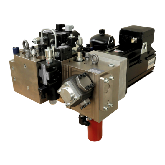
Control for CNC press brakes
Control for CNC press brakes
type ePrAX modular
type ePrAX modular
Assembly instructions
Assembly instructions
Operating pressure p
Operating pressure p
max
max
Volume ow V
Volume ow V
:
:
max
max
B 6340
B 6340
02-2021 -1.1 en
02-2021 -1.1 en
:
:
320 bar
320 bar
50 L/min
50 L/min
Advertisement
Table of Contents

Related Manuals for HAWE Hydraulik ePrAX-modular


Summary of Contents for HAWE Hydraulik ePrAX-modular
- Page 1 Control for CNC press brakes Control for CNC press brakes type ePrAX modular type ePrAX modular Assembly instructions Assembly instructions Operating pressure p Operating pressure p 320 bar 320 bar Volume ow V Volume ow V 50 L/min 50 L/min B 6340 B 6340 02-2021 ...
- Page 2 HAWE Hydraulik respects these legal provisions in all cases. HAWE Hydraulik cannot provide individual guarantees that the stated circuits or procedures (including in part) are not subject to the intellectual property rights of third parties.
-
Page 3: Table Of Contents
Exchanging the contamination indicator......................59 7.2.8 Exchanging the servo motor..........................59 7.2.9 Exchanging the servo motor and resolver cable....................60 7.2.10 Exchanging drive controller, brake resistance, and line lter.................. 60 Disassembly and disposal..........................61 Troubleshooting..............................62 HAWE Hydraulik SE B 6340 - 02-2021 - 1.1 3/73... - Page 4 System - parts list............................66 10.2.1 Cylinder module............................... 66 10.2.2 Slow Up module............................... 66 10.2.3 ServoPowerModule............................66 10.2.4 Tank module..............................68 10.3 Circuit diagram..............................68 10.4 Circuit diagram legend............................70 4/73 B 6340 - 02-2021 - 1.1 HAWE Hydraulik SE...
-
Page 5: About This Instruction
The manual provides relevant information for the machine manufacturer and machine operator as well as for training courses. You can request further information on the product at: HAWE Hydraulik SE, Einsteinring 17, 85609 Aschheim/Munich, Germany. 1.2 Safety instructions and symbols... -
Page 6: Applicable Documents
Hydraulic uid power - General rules and safety requirements for systems and their components DIN EN 12622:2009+A1:2013 Safety of machine tools - Hydraulic press brakes B 5488 General operating instructions: Assembly, commissioning and maintenance 6/73 B 6340 - 02-2021 - 1.1 HAWE Hydraulik SE... -
Page 7: For Your Safety
► Avoid re, open ames and smoking in the vicinity of the product. ► Immediately dispose of combustible materials wetted with hydraulic uid as special waste. ► Do not use ammable or corrosive cleaning uids. HAWE Hydraulik SE B 6340 - 02-2021 - 1.1 7/73... -
Page 8: Duties Of The Operator
► Activities other than those described in these instructions may only be performed by HAWE or authorized specialist companies. ► The personnel must have read and understood these instructions. 8/73 B 6340 - 02-2021 - 1.1 HAWE Hydraulik SE... -
Page 9: Personal Protective Equipment
The personal protective equipment is intended to prevent and reduce dangers. In the instructions, safety instructions with mandatory symbols indicate the wearing of special protective equipment for special activities. The instruction and supply is carried out by the operator. HAWE Hydraulik SE B 6340 - 02-2021 - 1.1 9/73... -
Page 10: About This Product
In the following, the left-sided structure and the left-sided assembly are shown as an example. All procedures described for the left side also apply to the structure and assembly on the right side in a mirrored fashion. 10/73 B 6340 - 02-2021 - 1.1 HAWE Hydraulik SE... - Page 11 2-QM1 2/2-way poppet valve 82-QM1 2/2-way poppet valve 1-QM7/ 1-BP1/ 2-QM7 2-BP1 1-QM3/ 1-RV2/ 2-QM3 2-RV2 1-QM2/ 2-QM2 81-RV2/ 82-RV2 1-UR1/ 2-UR1 81-RV1/ 82-RV1 HAWE Hydraulik SE B 6340 - 02-2021 - 1.1 11/73...
- Page 12 ange face Slow Up module (81-UR1/82-UR1); if the module is not required, the ange face is sealed ■ with a locking plate threaded connectors P1 and T2 to tool clamping option ■ Slow Up module (option) 12/73 B 6340 - 02-2021 - 1.1 HAWE Hydraulik SE...
- Page 13 82-CM1 diaphragm accumulator 82-QM1 2/2-way poppet valve 82-RV1 pressure relief valve cylinder module interface 82-RV2 pressure relief valve 82-UR1 interface to Slow Up module ServoPower module 11-RV1 11-BP1 11-HQ1 11-XN1 HAWE Hydraulik SE B 6340 - 02-2021 - 1.1 13/73...
- Page 14 A seal is mounted on the tank cover. A mini measurement connection (MI) on the tank cover is used to connect the return line for bleeding the system when the system is started up for the rst time. 14/73 B 6340 - 02-2021 - 1.1 HAWE Hydraulik SE...
-
Page 15: Functions
As safety-related parts of the controller (SRP/CS), the valves 1-QM2/2-QM2, 1-QM3/2-QM3, 1-QM4/2- QM4 and 1-QM5/2-QM5 (actuator) are controlled by a programmable electronic controller (PES) and its position switches 1-BG2/2-BG2, 1-BG3/2-BG3, 1-BG4/2-BG4, 1-BG5/2-BG5 (sensor) are monitored according to the function diagram. HAWE Hydraulik SE B 6340 - 02-2021 - 1.1 15/73... - Page 16 2-MB6 1-MB7 2-MB7 1-BG2* 2-BG2* 1-BG3* 2-BG3* 1-BG4* 2-BG4* 1-BG5* 2-BG5* *NC contact (PIN 4) IDLE DECOMPRESSION PRECLOSING SLOW UP FAST DOWN WAIT MUTE PREOPENING WORKING SPEED FAST SPEED UP 16/73 B 6340 - 02-2021 - 1.1 HAWE Hydraulik SE...
- Page 17 In IDLE mode, the press beam keeps its position. The Y-axis is in a safe state. ■ With the release from the machine controller, the speed control of the electric drives is enabled via input 1-T01/DI0 and 2-T01/DI0. HAWE Hydraulik SE B 6340 - 02-2021 - 1.1 17/73...
- Page 18 By means of the valve positions, the P connection of the pump is connected to the rod side and ■ system pressure M1 rises. PRECLOSING mode ends after the adjustable PRECLOSING TIME and the valve solenoids 1-MB2/2-MB2 ■ and 1-MB3/2-MB3 are energized. 18/73 B 6340 - 02-2021 - 1.1 HAWE Hydraulik SE...
- Page 19 Before start-up and during the FAST DOWN phase, the machine controller must monitor outputs 1-T01/DO0 and 2-T01/DO0 “Drive active” of the electric drives and stop the motion via the valves, if necessary. HAWE Hydraulik SE B 6340 - 02-2021 - 1.1 19/73...
- Page 20 WORKING SPEED mode using the linear measurement systems. If the permissible speed is exceeded, the safety controller stops the motion and the valves 1-QM2/2-QM2, 1-QM4/2-QM4 and 1-QM5/2-QM5 drop out. 20/73 B 6340 - 02-2021 - 1.1 HAWE Hydraulik SE...
- Page 21 The valve positions and the motor-pump speed result in a variable output throttle on the piston side ■ that is used to control the speed of the press beam. HAWE Hydraulik SE B 6340 - 02-2021 - 1.1 21/73...
- Page 22 The machine controller species the target speed for the electric drives via analog inputs 1-T01/AI0 ■ and 2-T01/AI0 and can, if necessary, limit the torque via analog inputs 1-T01/AI1 and 2-T01/AI1. The Y-axis of the hydraulic press is in a position-controlled state. ■ 22/73 B 6340 - 02-2021 - 1.1 HAWE Hydraulik SE...
- Page 23 By means of the valve positions, the P connection of the pump is connected to the rod side and ■ system pressure M1 rises. HAWE Hydraulik SE B 6340 - 02-2021 - 1.1 23/73...
-
Page 24: Control
Persons cannot reach in the danger zone of the hydraulic power unit. ■ Persons cannot burn themselves on hot surfaces. Label hot surfaces that endanger persons after the ■ hydraulic power unit is installed in the complete machine. 24/73 B 6340 - 02-2021 - 1.1 HAWE Hydraulik SE... - Page 25 P of the Servo Power Module a minimum pressure of 10 bar is reached. This can be achieved by increasing the weight of the upper beam or decreasing the maximum speed respectively. HAWE Hydraulik SE B 6340 - 02-2021 - 1.1...
-
Page 26: Transport And Storage
Slow Up, tool clamping modules if applicable ■ tank module (without the connecting line and fastening materials between the tank module and ■ cylinder module) The hydraulic uid is not included in the scope of delivery. 26/73 B 6340 - 02-2021 - 1.1 HAWE Hydraulik SE... -
Page 27: Checking The Delivery
Document transport damage with photos and report to the manufacturer. 3. Properly dispose of the product packaging in accordance with local regulations. DAMAGE For any defect found, le a complaint immediately with: HAWE Hydraulik SE Einsteinring 17 85609 Aschheim near Munich, Germany Tel.: +49 89 379100-1000 Claims for damage compensation can only be enforced during the applicable notification periods. -
Page 28: Assembly And Installation
► Remove any spilled or discharged hydraulic uid with a suitable aid. DAMAGE Material damage due to mechanical damage Protect the product from mechanical damage during assembly and installation, e.g. by padding. 28/73 B 6340 - 02-2021 - 1.1 HAWE Hydraulik SE... -
Page 29: Mechanical Connection
5.1.1 Preparing the hydraulic cylinder CM050 (260) Ø73-1 max. Ø11 min.150 4xM24 109±0.1 54±0.2 54±0.2 min.110 Ra0.8 0.01/100 CM063 Ra 0.8 (300) 4x M30 max. Ø14.5 max. Ø88 min.180 95±0.1 55±0.2 55±0.2 min.110 0.01/100 HAWE Hydraulik SE B 6340 - 02-2021 - 1.1 29/73... - Page 30 4. Countersink the Ø 21 mm (CM050) or Ø 26.5 mm (CM063) holes for the M24 (CM050) or M30 (CM063) threads. 5. Cut an M24 (CM050) or M30 (CM063) thread in the Ø 21 mm (CM050) or Ø 26.5 mm (CM063) holes made for this purpose. 30/73 B 6340 - 02-2021 - 1.1 HAWE Hydraulik SE...
-
Page 31: Mounting The Cylinder Modules On The Hydraulic Cylinders
8. Manually tighten the hexagon socket screws on the hydraulic cylinder. 9. Tighten the hexagon socket screws to a torque of 1160 ± 100 Nm (M30) or 590 ± 25 Nm (M24). HAWE Hydraulik SE B 6340 - 02-2021 - 1.1... -
Page 32: Mounting The Servo Power Modules On The Cylinder Modules
9. Insert the hexagon socket screws (S) through the provided holes of the plate and Servo power module. 10. Manually tighten the hexagon socket screws on the cylinder module. 11. Tighten the hexagon socket screws with a torque of 65 ± 2 Nm. 32/73 B 6340 - 02-2021 - 1.1 HAWE Hydraulik SE... -
Page 33: Mounting The Tank Module
The M8 threads have been introduced into the machine frame according to the following hole pattern. 1. Lift the tank module by attaching suitable lifting equipment to the tabs (L). HAWE Hydraulik SE B 6340 - 02-2021 - 1.1 33/73... -
Page 34: Hydraulic Connection
1. Check the position and condition of the existing seals on both ends of the hydraulic hose (HS). 2. Manually tighten one end of the hydraulic hose with two ange halves on the SAE connection of the corresponding cylinder module (CM) or tank module (TM). 34/73 B 6340 - 02-2021 - 1.1 HAWE Hydraulik SE... -
Page 35: Electrical Connection
Delivery without motor ange and servo motor The direction of rotation of the motor must be adapted to the direction of rotation of the pump (see arrow on pump housing ring). HAWE Hydraulik SE B 6340 - 02-2021 - 1.1 35/73... - Page 36 2. Connect the servo motor (4) to the drive controller via the motor line and the resolver line. 3. Connect the switch cabinet to the electrical power supply. 4. Check the electrical connections after operating the equipment for one week. 36/73 B 6340 - 02-2021 - 1.1 HAWE Hydraulik SE...
-
Page 37: Interfaces
0 – 800 VDC power supply Negative (-) Protective earth conductor external brake resistance DC+/B+ Ext. brake resistance: positive Ext. brake resistance: negative internal brake resistance Int. brake resistance: positive Jump Int. brake resistance: positive HAWE Hydraulik SE B 6340 - 02-2021 - 1.1 37/73... - Page 38 ± 10 % asymmetry ± 3 % Performance data may vary (depending on the motor and inverter used). Power supply interface (port P1) External brake resistance (port P1) 38/73 B 6340 - 02-2021 - 1.1 HAWE Hydraulik SE...
- Page 39 Motor and resolver Drive controller motor output (port P2) HAWE Hydraulik SE B 6340 - 02-2021 - 1.1 39/73...
- Page 40 Motor power interface (port P2) Encoder (port E1) Drive controller control interface 40/73 B 6340 - 02-2021 - 1.1 HAWE Hydraulik SE...
- Page 41 (AUX power) type voltage fluctuation ± 15% (22.8–25.2 V) rated power 72 W rated current Performance data may vary (depending on the motor and inverter used). Communication (port U1/U2) HAWE Hydraulik SE B 6340 - 02-2021 - 1.1 41/73...
- Page 42 The fault is acknowledged via the Dl1 input. PNP open collector, 24 V, 100 mA max. 24 V Not connected Not connected Functions of the inputs and outputs of plugs U2 42/73 B 6340 - 02-2021 - 1.1 HAWE Hydraulik SE...
- Page 43 Actual current feedback 0–10 V f.s., 30 Analog output Analog ground Analog ground reference AO1 reference Not connected Not connected Not connected Not connected Not connected Not connected Not connected Drive controller start-up HAWE Hydraulik SE B 6340 - 02-2021 - 1.1 43/73...
- Page 44 IP65 with mounted female connector 1-MB5/2-MB5 Connection type Plug-in connection DIN EN 175301-803-PG09 Rated voltage 24 VDC Rated power 30 W (CM050), 45 W (CM063) Degree of protection IP65 with mounted female connector 44/73 B 6340 - 02-2021 - 1.1 HAWE Hydraulik SE...
- Page 45 1-BG2 / 2-BG2, 1-BG3 / 2-BG3, 1-BG4 / 2-BG4, 1-BG5 / 2-BG5 power supply 24 VDC max. output current < 150 mA Sensorstecker M12 x 1.4 pins ground Connection Supply Normally open (NO) contact Ground Normally closed (NC) contact HAWE Hydraulik SE B 6340 - 02-2021 - 1.1 45/73...
- Page 46 Max. 1 A Switching point 60 °C 150 mm Connection type Plug-in connection DIN 175301-803-PG09 Degree of protection IP65 with mounted female connector Contact assignment Level switch Supply Temperature switch 46/73 B 6340 - 02-2021 - 1.1 HAWE Hydraulik SE...
-
Page 47: Start-Up
The pressure relief valve 11-RV1 is set to 320 bar at the factory. ■ The diaphragm accumulator 81-CM1/82CM1 must be lled to p0 with nitrogen (only for cylinder ■ block with slow up option). Structure HAWE Hydraulik SE B 6340 - 02-2021 - 1.1 47/73... - Page 48 (MI) on the associated tank module. b) Completely screw in the adjustment screw of the pressure relief valves 81-RV2/82-RV2. c) Energize valves 1-QM4 and 1-QM6, and 2-QM4 and 2-QM6. 48/73 B 6340 - 02-2021 - 1.1 HAWE Hydraulik SE...
- Page 49 Retract the press beam at a fast speed of 230 mm/s to upper stop. e) Repeat 3-4 times until abnormal pump noises (due to the suction of air) are no longer audible at the Servo power modules. HAWE Hydraulik SE B 6340 - 02-2021 - 1.1 49/73...
- Page 50 (MI) and into the tank without bubbles. ATTENTION: The cylinder rod can move up. d) De-energize all valves and set motor speed to 0 rpm. 7. Bleed / ll cylinder module on the piston side of the hydraulic cylinder: 50/73 B 6340 - 02-2021 - 1.1 HAWE Hydraulik SE...
- Page 51 The axes must be controllable individually as well as together. 1. Fill the tank module with oil (lling level minimum 295 mm): a) Check that the system is depressurized. b) Unscrew the oil dip stick. HAWE Hydraulik SE B 6340 - 02-2021 - 1.1 51/73...
- Page 52 (MI) and into the tank without bubbles. ATTENTION: The cylinder rod can move up. d) De-energize all valves and set motor speed to 0 rpm. 8. Retract the hydraulic cylinder: 52/73 B 6340 - 02-2021 - 1.1 HAWE Hydraulik SE...
-
Page 53: Switching The Hydraulic System On/Off
6.1 Switching the hydraulic system on/off The hydraulic system is switched on and off via the system controller. Initial start-up of the system must have been performed properly. HAWE Hydraulik SE B 6340 - 02-2021 - 1.1 53/73... -
Page 54: Maintenance
Lack of maintenance or poor maintenance can cause the hydraulic system to malfunction. Improperly performed maintenance and improperly performed troubleshooting and fault elimination can endanger maintenance and operating personnel. ► Read and abide by all instructions provided in this section. 54/73 B 6340 - 02-2021 - 1.1 HAWE Hydraulik SE... -
Page 55: Maintenance Plan
Bleeding the hydraulic system ✓ Checking the lling level of the hydraulic uid ✓ Exchanging the hydraulic uid ✓ Exchanging air lter ✓ Exchanging hydraulic lter ✓ Checking cable for damage HAWE Hydraulik SE B 6340 - 02-2021 - 1.1 55/73... -
Page 56: Service
The hydraulic lter is monitored by the contamination indicator. If the contamination indicator outputs a signals with the machine at operating temperature, the hydraulic uid, hydraulic lter and the air lter must be exchanged. 18-QR1 18-VZ1 11-HQ1 56/73 B 6340 - 02-2021 - 1.1 HAWE Hydraulik SE... -
Page 57: Exchanging The Level Switch
20. Dispose of the hydraulic uid, the container for the hydraulic uid and any cleaning cloths contami- nated with hydraulic uid as required by regulations. 7.2.4 Exchanging the level switch The hydraulic system is switched off and secured against unintentional restart. The system is pressureless. HAWE Hydraulik SE B 6340 - 02-2021 - 1.1 57/73... -
Page 58: Exchanging Valves
5. Mount the cable on the pressure sensor. 6. Remove any oil that has been discharged on the cylinder module. 7. Bleed the hydraulic system as described in section "Start-up". 58/73 B 6340 - 02-2021 - 1.1 HAWE Hydraulik SE... -
Page 59: Exchanging The Contamination Indicator
4. Release the four fastening screws (S) on the servo motor. 5. Remove the coupling hub on the servo motor; to do so, release the clamping screw and pull off the coupling hub. HAWE Hydraulik SE B 6340 - 02-2021 - 1.1 59/73... -
Page 60: Exchanging The Servo Motor And Resolver Cable
4. Remove the component from the switch cabinet. 5. Mount the new component in the switch cabinet. 6. Connect the cables to the new component as described in section "Electrical connection". 60/73 B 6340 - 02-2021 - 1.1 HAWE Hydraulik SE... -
Page 61: Disassembly And Disposal
uid according to the regional waste disposal requirements. ► Dispose of the electronic components at approved collection points or with approved disposal companies according to local regulations. ► Dispose of metal with approved specialist disposal companies. HAWE Hydraulik SE B 6340 - 02-2021 - 1.1 61/73... -
Page 62: Troubleshooting
Perform an oil analysis. Replace the lter element hydraulic uid the hydraulic uid and hydraulic uid. External leakage at the faulty seal visual inspection Replace the seal. valve 62/73 B 6340 - 02-2021 - 1.1 HAWE Hydraulik SE... -
Page 63: Appendix
10–95% (non-condensing) Storage storage environment indoor storage in direct sunlight storage in explosive atmosphere min. storage temperature -20 °C max. storage temperature +50 °C max. permissible air humidity 10–95% (non-condensing) HAWE Hydraulik SE B 6340 - 02-2021 - 1.1 63/73... -
Page 64: Weights And Measures
ange surface to CM SAE ange connection 2 ½”. adjustment parts Cylinder module (CM): pressure relief valve 1-RV1/2-RV1 Slow Up module: pressure relief valve 81-RV2/82-RV2 ServoPower module (SPM): pressure relief valve 11-RV1 64/73 B 6340 - 02-2021 - 1.1 HAWE Hydraulik SE... -
Page 65: Hydraulic Data
Max. 1 A (drive controller 3 A per axis) operating mode/switch-on duration pressure sensor IP 67 level and temperature switch IP 65 with mounted female connector HAWE Hydraulik SE B 6340 - 02-2021 - 1.1 65/73... -
Page 66: System - Parts List
SVN221BE08PD HV08716 81-QM1/82-QM1 diaphragm accumulator 1.4 L-210 BAR KC9672_ 81-CM1/82-CM1 10.2.3 ServoPowerModule Designation in Wear parts Order number circuit diagram lter element 0110 R 010-LM210 - 3 BAR KC2130_ 11-HQ1 66/73 B 6340 - 02-2021 - 1.1 HAWE Hydraulik SE... - Page 67 - 10 m CR-X-A28-10-GTV KB3309A (for SPM2013PHS0003A004-24) CR-X-A28-10-GTV KB3309A (for SPM2019PHS0001A001-42) Designation in Mechanical components Order number circuit diagram pressure relief valve VDBE08EE HV07636 11-RV1 contamination indicator 2.4 BAR KC3694 11-BP1 HAWE Hydraulik SE B 6340 - 02-2021 - 1.1 67/73...
-
Page 68: Tank Module
Designation in circuit diagram air lter 3 MY KC2224_ 18-VZ1 Designation in circuit diagram Electrical components Order number level switch L 150 T70OE KC3550 18-BZ1 10.3 Circuit diagram CM050 (left) 68/73 B 6340 - 02-2021 - 1.1 HAWE Hydraulik SE... - Page 69 CM063 (left) HAWE Hydraulik SE B 6340 - 02-2021 - 1.1 69/73...
-
Page 70: Circuit Diagram Legend
2/2-way seated valve 81-QM1 check valve 81-RM1 check valve 81-RM2 throttle valve 81-RN1 throttle valve 81-RN2 throttle valve 81-RN3 pressure relief valve 81-RV1 pressure relief valve 81-RV2 Slow up module 81-UR1 70/73 B 6340 - 02-2021 - 1.1 HAWE Hydraulik SE... - Page 71 82-QM1 82-MB1 2/2-way seated valve 82-QM1 check valve 82-RM1 check valve 82-RM2 nozzle 82-RN1 nozzle 82-RN2 nozzle 82-RN3 pressure relief valve 82-RV1 pressure relief valve 82-RV2 Slow up module 82-UR1 HAWE Hydraulik SE B 6340 - 02-2021 - 1.1 71/73...
- Page 72 11-XN1 Tank module Component Designation in circuit diagram temperature sensor 18-BL1 temperature switch 18-BT1 level switch 18-BZ1 hydraulic uid drain screw 18-QR1 air lter 18-VZ1 tank module 18-UZ1 72/73 B 6340 - 02-2021 - 1.1 HAWE Hydraulik SE...
- Page 75 ■ ■ ■ You can nd further information on HAWE Hydraulik, your local contact and the range of hydraulic training sessions offered at: www.hawe.com. HAWE Hydraulik SE Einsteinring 17 | 85609 Aschheim/München | Postfach 11 55 | 85605 Aschheim |...
Need help?
Do you have a question about the ePrAX-modular and is the answer not in the manual?
Questions and answers