
Related Manuals for HAWE Hydraulik CDK Series


Summary of Contents for HAWE Hydraulik CDK Series
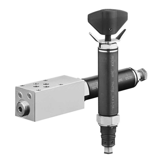
- Page 1 Pressure-reducing valve type CDK Product documentation Screw-in valve Operating pressure p 500 bar Volumetric ow rate Q 22 l/min D 7745 09-2019-1.9...
- Page 2 Brand names, product names and trademarks are not specifically indicated. In particular with regard to registered and protected names and trademarks, usage is subject to legal provisions. HAWE Hydraulik respects these legal provisions in all cases. Printing date / document generated on: 11.11.2019 ©...
-
Page 3: Table Of Contents
Screwing in the screw-in valve..........................20 5.2.2 Setting the pressure............................20 5.2.3 Creating the mounting hole..........................21 5.2.4 Making base plate.............................. 21 Operating instructions............................22 Maintenance information............................. 22 Other information.............................23 Planning information............................23 Application examples............................24 © HAWE Hydraulik SE D 7745 - 09-2019-1.9 3/25... -
Page 4: Overview Pressure Control Valve Type Cdk
For pipe connection (without/with pressure-limiting valve) ■ For manifold mounting (without/with pressure-limiting valve) ■ For manifold mounting (without/with pressure-limiting valve) ■ with adapter plate for pipe connection Version with connection block for manifold mounting © HAWE Hydraulik SE 4/25 D 7745 - 09-2019-1.9... -
Page 5: Available Versions, Main Data
Circuit symbol No designation Fixed, can be adjusted using tool Can be adjusted by hand, with lock nut (not for type CDK 3.K) Rotating grip with lock (not for type CDK 3.K) © HAWE Hydraulik SE D 7745 - 09-2019-1.9 5/25... -
Page 6: Versions With Individual Connection Block For Pipeline Connection
200 ... 700 - DG 34 100 ... 400 - DG 35 40 ... 210 - DG 36 4 ... 12 - DG 364 4 ... 50 - DG 365 12 ... 170 © HAWE Hydraulik SE 6/25 D 7745 - 09-2019-1.9... -
Page 7: Versions With Individual Connection Block For Plate Mounting
Plate mounting, pressure relief valve, xed, can be adjusted using tool P - ... - 1/4 Plate mounting SP - ... /... - 1/4 Plate mounting, pressure relief valve, xed, can be adjusted using tool, with adapter plate for pipeline connection © HAWE Hydraulik SE D 7745 - 09-2019-1.9 7/25... -
Page 8: Parameters
Permissible temperature during start: -40°C (observe start-viscosity!), as long as the service temperature is at least 20K higher for the following operation. Biologically degradable pressure uids: Observe manufacturer's specifications. By considera- tion of the compatibility with seal material not over +70°C. © HAWE Hydraulik SE 8/25 D 7745 - 09-2019-1.9... - Page 9 = 6 lpm (CDK 32) P → A max = 12 lpm (CDK 3) = 22 lpm (CDK 35) = 25 lpm See note in Chapter 3, "Parameters" A → P max © HAWE Hydraulik SE D 7745 - 09-2019-1.9 9/25...
- Page 10 Δp - Q - Characteristic curve P→A or A→P Volumetric ow rate (lpm); Δp Flow resistance (bar) NOTE For this purpose, please observe the additional information under the point "Flow direction". © HAWE Hydraulik SE 10/25 D 7745 - 09-2019-1.9...
- Page 11 - 1/4 - DG.. = 1.6 kg - 1/4 S(SR) = 1.6 kg = 1.1 kg - SP = 1.6 kg - P-../..-1/4 = 1.5 kg - SP-../..-1/4 = 2.0 kg © HAWE Hydraulik SE D 7745 - 09-2019-1.9 11/25...
-
Page 12: Dimensions
For this purpose, please also observe the information on threads and on producing requirements in Chapter 5.2, "Assembly information"! Type CDK 3.K: Do not turn set screw 8 beyond the red marker ring! Adjustment No designation Coding R Coding H © HAWE Hydraulik SE 12/25 D 7745 - 09-2019-1.9... -
Page 13: Mounting Hole
Additionally the passage between port A and T is sealed at the screwin port and the internal piston. Counterbore 0.5 (max. #30 ), exclusively required for pressures at A in excess of 100 bar. +0.2 +0.1 © HAWE Hydraulik SE D 7745 - 09-2019-1.9 13/25... -
Page 14: Version With Single Connection Block For Pipe Connection
9/16-18 UNF ANSI B1.1, SAE-6 - 9/16-18 UNF-DG.. Screw-in valve, as per Chapter 4.1, "Screw-in valve" Pressure switch DG 3.. as per D 5440 Without DG 3.. (can be retrofitted here) © HAWE Hydraulik SE 14/25 D 7745 - 09-2019-1.9... - Page 15 D 5440 Without DG 3.. (can be retrofitted here) CDK 3..- 1/2 Coding Connections P, A - 1/2 G 1/2 (BSPP) ISO 228-1 Screw-in valve, as per Chapter 4.1, "Screw-in valve" © HAWE Hydraulik SE D 7745 - 09-2019-1.9 15/25...
- Page 16 CDK 3..- 1/4 S CDK 3..- 1/4 SR Coding Connections P, A, R - 1/4 S Fixed G 1/4 (BSPP) ISO 228-1 - 1/4 SR Adjustable © HAWE Hydraulik SE 16/25 D 7745 - 09-2019-1.9...
-
Page 17: Version With Connection Block For Manifold Mounting
CDK 3(32, 35) - .. - SP - .. - 1/4 Adapter plate (connection block for pipe connection) Sealing with O-rings 7.65x1.78 NBR 90 Sh Identifier Connections P, A, R - P .. G 1/4 (BSPP) ISO 228-1 - SP .. © HAWE Hydraulik SE D 7745 - 09-2019-1.9 17/25... -
Page 18: Base Plate Hole Pattern
O-ring 21.95x1.78 AU 90 Sh Sealing ring A25x30x2 DIN 7603-Cu KANTSEAL DKAR00021-N90 NBR 90 Sh 23.52 x 26.88 x 1.68 Tapped plug and locking tapped plug complete order no.. 7710 029 © HAWE Hydraulik SE 18/25 D 7745 - 09-2019-1.9... -
Page 19: Assembly, Operation And Maintenance Recommendations
Risk to life caused by sudden movement of the hydraulic drives when dismantled incorrectly! Risk of serious injury or death. Depressurise the hydraulic system. ■ Perform safety measures in preparation for maintenance. ■ © HAWE Hydraulik SE D 7745 - 09-2019-1.9 19/25... -
Page 20: Screwing In The Screw-In Valve
Risk of injury on overloading components due to incorrect pressure settings! Risk of minor injury. Pay attention to the maximum operating pressure of the pump and the valves. ■ Always monitor the pressure gauge when setting and changing the pressure. ■ © HAWE Hydraulik SE 20/25 D 7745 - 09-2019-1.9... -
Page 21: Creating The Mounting Hole
The hole pattern corresponds to that of type ADM 11 P as per 7120. The O-ring counterbore for the drain port R (or L) is present but is only required for type CDK..-SP. See hole pattern in Chapter 4.5, "Base plate hole pattern" © HAWE Hydraulik SE D 7745 - 09-2019-1.9 21/25... -
Page 22: Operating Instructions
Conduct a visual inspection at regular intervals, but at least once per year, to check if the hydraulic connections are damaged. If external leakages are found, shut down and repair the system. Clean the device surface of dust deposits and dirt at regular intervals, but at least once per year. © HAWE Hydraulik SE 22/25 D 7745 - 09-2019-1.9... -
Page 23: Other Information
The ratio of thermal expansion coefcient to coefcient of compressibility (theoretically 1:10, i.e. ΔT = 1K →Δp ≈ 10 bar) is based on the fact described above. As consumers, pipes and hoses will yield, in reality (based on experience) a ratio of approx. 1:1 can be assumed. © HAWE Hydraulik SE D 7745 - 09-2019-1.9 23/25... -
Page 24: Application Examples
Type CDK 3- 2-1/4-DG 34 E.g. type RK 2G in accordance with D 7445 = 45 l/min = 15 l/min Type CDK 3-2-1/4 CDK 3-5 - 80 CDK 3-5 - 40 © HAWE Hydraulik SE 24/25 D 7745 - 09-2019-1.9... - Page 25 Valve bank (directional seated valve) type BVH: D 7788 BV ■ Intermediate plate type NZP: D 7788 Z ■ HAWE Hydraulik SE Einsteinring 17 | 85609 Aschheim/Munich | Postfach 11 55 | 85605 Aschheim | Germany Tel +49 89 379100-1000 | Fax +49 89 379100-91000 | info@hawe.de | www.hawe.com...
Need help?
Do you have a question about the CDK Series and is the answer not in the manual?
Questions and answers