
Subscribe to Our Youtube Channel
Related Manuals for Nissei NS-60A


Summary of Contents for Nissei NS-60A
- Page 1 INSTRUCTION MANUAL Vector Impedance Antenna Analyzer Model: NS-60A (HF) NS-520A (VHF/UHF) RADIO COMMUNICATION EQUIPMENT Caution: Read all instructions before operation equipment...
- Page 2 Features and Functions: The analyzer breaks the size barrier for RF- analyzers by delivering user-friendly convenience top- notch accuracy. And a vivid TFT multi-color display in an ultra-compact package. This unit is loaded with a great selection of Single-Frequency and Swept-Frequency VNA functions.
- Page 3 The analyzer has the advanced DDS stimulus generator delivers rock-solid stability, smooth skip-free tuning. There’s also a built-in Field-Strength Indicator to warm when high interference levels are present. This unit long-rinning lithium-polymer power source is built right in. Simply connect to any available USB port on your computer or USB wall charger to recharge.
-
Page 4: Specifications
VSWR range: 1 : 1.00 - 1 : 99.99 Lord Resistance (R): 0.1 - 999.9 ohms Lord Reactance (X): 0.1 - 999.9 ohms Impedance Magnitude (Z): 0.1 - 999.9 ohms 3.Frequency range: NS-60A: 0.5-60 MHz NS-520A: 133-177 / 195-280 / 395- 520 MHz Frequency Stability: NS-60A: <3PPM... - Page 5 Power Source: Built-in 3.7-V,1900-mAH Lithium Polymer battery. Charge source: Any USB port,Analyzer accepts Micro-USB plug. AC power adapter output voltage is 5.0-5.5VDC, and the current output capacity > 500mA. Charge indicator: RED LED signals normal charging, Green LED indicates when charging is complete. RF Connector: BNC-female.
-
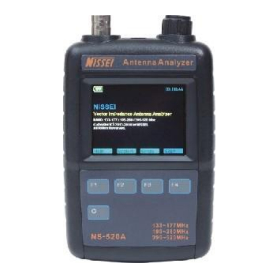
Page 6: Layout And Controls
Layout and Controls: Antenna Analyzer 00 :20: 08 Brand BV2NW Vector Impedance Anatenna Analy zer He lp Sy st em Si ng le S c an F3 F4 15 16 BNC-female. RF Connector: Rotary Encoder: Tunes DDS frequency when setting up tests,positions marker and scrolls for some system set-up functions. - Page 7 11.Buzzer: Audio modulated tone buzzer. If system c rash,can reset processor. Reset-Key Battery cover plate Hang rope hole Charge indicator LED Micro USB For charging use. 17.Undefined. Power Source and Initial Setup: Charging the battery: The analyzer is powered by a 3.7-V,1900-mAH Lithium Polymer battery.
- Page 8 Press the switch labeled “ System” Press Select to toggle between Auto-off and Callsign, Select Callsign. Press the Encoder Knob to toggle the curser to the start (or left) position. Rotate the Encoder to scroll in your first character. Press the Encoder and move to the second character.
- Page 9 Other notes: In the lower right of the screen, there is a measure SCAN antenna signal strength indicator. No test operation, the display case of the antenna interference field strength induced. During the test, the case represents the measured excitation power output. Single measurement interface, there is a S-Antenna signal strength indicator, which is a rough indication of the antenna sensing...
- Page 10 A.SACN mode: From the Boot Screen, press the Scan key, The screen is shown in figure below: Press the scan key (SPAN),select the appropriate SACN measurement bandwidth. Rotary encoder potentiometer (by pressing the encoder switch at the top of the cycle to select the input bits, at the bottom with a yellow indicator) entering the center frequency...
- Page 11 After the end of the measurement, automatically enters - Present- interface In this interface, you can perform 3 operations: Press ”Graph” icon mode button to switch the scan results of the curve display, in addition to standing SWR curve, as well as Z curve, R curve, X curve. Move the cursor, view the scan frequency point on the curve on each scan of the specific parameters of the measurement results.
- Page 12 Scan data save and read: When unit is shutdown, it will automatically save the last set of scan data into memory. When power on: Press the “Scan” (scanning)function selection key, enter Scan-Set interface. Press “Graph” (scan curve) icon mode selection key, it will automatically transfer the stored scan data.
- Page 13 Single frequency mode provides a single frequency impedance measurement. The measured frequency of the basic parameters are displayed on the screen. And to indicated the form of bars and numbers Displayed on the screen quickly. the scanning will not stop, until you press the Stop button.
Need help?
Do you have a question about the NS-60A and is the answer not in the manual?
Questions and answers