Table of Contents
Advertisement
Advertisement
Table of Contents

Related Manuals for Nissei DG-503


Summary of Contents for Nissei DG-503
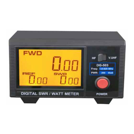
- Page 1 NISSEI SERVICE MANUAL DG-503 RANGE : 1.6 - 525 MHz Max. Power : 200W...
-
Page 2: Table Of Contents
SERVICE MANUAL TABLE OF CONTENT MODEL : DG-503 SWR & POWER METER 1.6-525 MHz SECTION SUBJECT: 1. INTRODUCTION Main features..................Specification................2. ALIGNMENT Test equipment................Forward power (125-525Mhz)............SWR alignment (125-525Mhz)............Forward power (1,6-60Mhz)............... SWR alignment (1.6-60Mhz).............. Final alignment................Alignment spots photo………………………………………………... -
Page 3: Introduction
C. LCD backlight display D. Convenient control layout for easy operation E. Packing gift box and DC 12V wire. 1.2 SPECIFICATIONS MODEL DG-503 Frequency Range 1.6-60 MHz / 125-525 MHz Caibration point 14MHz / 50MHz / 145MHz / 435MHz Power Range... -
Page 4: Alignment
I. Dummy Load 50 OHM, MAX. 200W X1, 25 OHM, MAX, 200W x 1 J. Ceramic adjusting driver Forward Power alignment (125-525 MHz coupler & PCB adjustment) Preset : Turn DG-503 switch to "VUHF", connect coupler plug to JP2 on C board A. Turn dual band transceiver to VHF 145.130 MHZ position "M"... -
Page 5: Swr Alignment (125-525Mhz)
5% tolerance Forward power alignment (1.6-60 MHZ) A. Turn HF transceiver to 28.5 MHz, connect BIRD 4421 + DG-503 + 50 Ohm dummy load. B. Turn DG-503 switch to "HF", connect coupler plug into JP1 on PCB C. -
Page 6: Alignment Spots Photo
Alignment spots photo (PCB-C driver board) - 5 -... -
Page 7: Main Board Schematic
3. SCHEMATIC 3.1 Main board schematic - 6 -... -
Page 8: Main Board Component Placement
3.2 Main board component placement - 7 -... -
Page 9: Exploded Drawing & Parts List
4. EXPLODED DRAWING & PARTS LIST 4-1 EXPLODED DRAWING 4-2 PARTS LIST Name Description Plate Name plate Plate Function plate Switch Slide Panel Plastic front panel Lens PMMA Display LCD display Backlight LED backlight sheet Button Push button PCB_B_Main Board Screw PCB_C_Driver Board PCB for slide SW... - Page 10 Brand: Nissei Type: DG503 Complaint: Bad read out or 000 read out ----------------------------------------------------------------------------------------------------------------- If the display shows 000, pls refer to the photo and apply fully soldering at the said 5 points.
Need help?
Do you have a question about the DG-503 and is the answer not in the manual?
Questions and answers