Advertisement
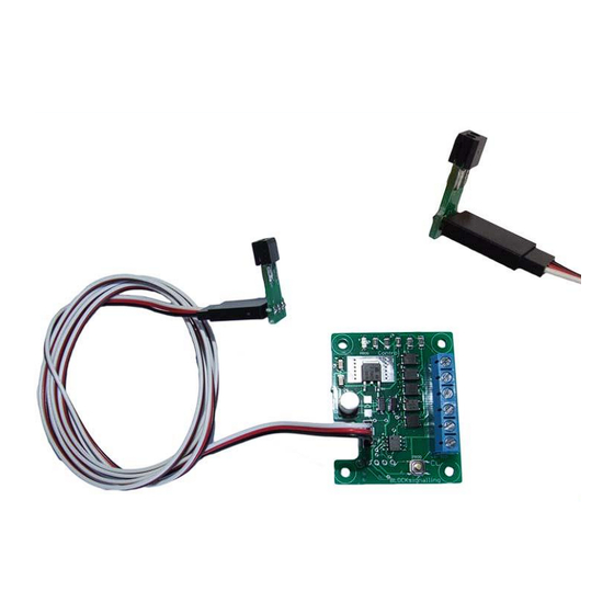
LED SIGNAL CONTROLLER ASP1B
FOR COMMON-CATHODE LED SIGNALS
This Signal Controller detects trains by bouncing invisible Infra-Red (IR) light off the
underside of the rolling stock, and detecting the light reflected back. Once triggered
by the train, the module runs built-programs to simulate the operation of 2-, 3- or 4-
aspect signals.
•
Uses an infra-red sensor mounted below the track to detect trains passing above
•
When a train is detected, the module triggers the signal to switch to red
•
Signal automatically switches back to green (through yellow and double-yellow if
appropriate)
•
Flexible programming options to suit different signals and to allow adjustment of
timings to suit
•
Realistic fading between aspects.
•
Yellow and Double-Yellow stages will change to red if another train passes.
•
Requires a 12V DC Supply
•
For Common-Anode Led signals only.
Advertisement
Table of Contents

Related Manuals for BLOCKsignalling ASP1B


Summary of Contents for BLOCKsignalling ASP1B
- Page 1 LED SIGNAL CONTROLLER ASP1B FOR COMMON-CATHODE LED SIGNALS This Signal Controller detects trains by bouncing invisible Infra-Red (IR) light off the underside of the rolling stock, and detecting the light reflected back. Once triggered by the train, the module runs built-programs to simulate the operation of 2-, 3- or 4- aspect signals.
-
Page 2: Power Supply
Building on the success of our infra-red train detectors, this module boasts smooth fading between aspects, and the ability to be triggered from yellow or double-yellow stages back to red. The signal normally shows green. When the train passes the detector, the signal switches to red. - Page 3 Programming As supplied, the module is programmed for 4-aspect signals. If you are using 3- or 2-aspect signals, then it will be necessary to reprogram the module. Programming for the particular application can be completed before or after testing the wiring, and also before or after completing the installation. This is performed by attaching the sensor and following the programming instructions below.
-
Page 4: Connecting The Outputs
Connecting the Outputs Each channel has an output, which switches to a positive voltage to light the attached signal led. There are resistors built-in to the controller, so no external resistors are required. If your signal already has resistors connected, these can remain if you wish, although the signal may appear slightly dimmer. -
Page 5: Sensitivity Setting
Sensitivity Setting The module is supplied with the sensitivity pre-set to suit most installations and should not need adjustment. In locations such as tunnels, or when the module is not being used under the track bed, then it may be desirable to adjust the detection threshold. The sensitivity is factory set to 5, and can be adjusted from 1 to 10 (with 1 being the most sensitive and 10 being the least sensitive). -
Page 6: Installation
Installation The Infra-Red sensor is normally installed below the track-bed. The detection range of the unit is up to approximately 25mm from the face of the package when the default sensitivity is set (for dark surfaces with low levels of reflectivity). - Page 7 Page 7 of 18...
- Page 8 Program 2 (2-Aspect Signalling) CH3+ GREEN CH1+ COM- POWER SUPPLY Led Connections BLOCK signalling This program simulates the operation of a two aspect signal, which is normally showing green. The module searches for a train, and if one is detected in front of the sensor, the signal immediately switches to red.
- Page 9 Program 3 (3-Aspect Signalling) CH3+ GREEN CH2+ YELLOW CH1+ COM- POWER SUPPLY Led Connections BLOCK signalling This program simulates the operation of a three aspect signal, which is normally showing green. The module searches for a train, and if one is detected in front of the sensor, the signal immediately switches to red.
- Page 10 seen. At this point, release the button. You will see a long flash of two seconds and then the led will begin flashing again. When 3 flashes have been seen press and hold the button. You will see a long flash of five seconds and then 10 rapid flashes.
- Page 11 The "red time" can be adjusted to a realistic duration for a train to clear the section of track protected by the signal. The "yellow time" and "double yellow time" can be adjusted to a realistic duration for the scale. To use this mode, the module needs to be reprogrammed as follows.
- Page 12 Example Wiring to Eckon or Berko 4-aspect Signal The positive connection from each of the leds in an Eckon or Berko signal match the led colour (red wire for the red led positive connection, etc). Depending on the age of the signal, there will be one or more white wires. These are the negative connections to the leds.
- Page 13 Changing the Timing of each Phase The individual time for each of the phases can be adjusted to suit (the default values are shown in the programming diagram below). Once you are happy with the operation of the train detection, you will probably want to change these to more realistic values.
- Page 14 store the second value (the time you want both yellow leds to be lit, for example 10 flashes for 10 seconds). When the button is released, the led flashes 10 times rapidly, and the module starts operating. Page 14 of 18...
- Page 15 Other Programming Options There are a number of parameters which can be adjusted if you wish to alter the operation of the module. Release Time This is the time that the infra-red sensor must be continuously unobstructed for the module to confirm the train has passed. This allows for gaps between the carriages of variable reflectivity of the underside of the train.
-
Page 16: Factory Reset
Program Flow Diagram As mentioned above, there are a number of memory locations which can programmed with different values to change the operation of the module. Before starting, it is a good idea to write down the memory locations and the values you are going to set them to. - Page 17 Page 17 of 18...
-
Page 18: Troubleshooting
4. With 2-aspect signals, there are times when neither is lit. The module needs to be programmed for 2-aspect signals. If it is programmed for 3- or 4- aspect signals, there will be times when yellow (and double yellow) indications would be shown. ©blocksignalling.co.uk 2022 Page 18 of 18...
Need help?
Do you have a question about the ASP1B and is the answer not in the manual?
Questions and answers